A num- ber of platforms (e.g. CORBA, J2EE, .NET) have been introduced which often came in bundle with their own programming language (e.g. C++, Java, C#).
Dipartimento di Informatica Universit`a di L’Aquila Via Vetoio, I-67100 L’Aquila, Italy http://www.di.univaq.it
P H .D. T HESIS IN C OMPUTER S CIENCE XIX
S PECIFICATION OF M ODEL T RANSFORMATION AND W EAVING IN M ODEL D RIVEN E NGINEERING
Ph.D. Thesis of: Davide Di Ruscio
Advisor: Prof. Alfonso Pierantonio
Supervisor of the Ph.D. Program: Prof. Michele Flammini
C ICLO XIX
c Davide Di Ruscio, 2007. All rights reserved
A BSTRACT Last years witnessed an increasing intricacy of both software systems and technologies. A number of platforms (e.g. CORBA, J2EE, .NET) have been introduced which often came in bundle with their own programming language (e.g. C++, Java, C#). This has made the software development process a difficult and expensive task. Model driven engineering (MDE) aims at preserving the investments in building complex software systems against constantly changing technology solutions, by advocating the raising of the abstraction level in system specification and increasing automation in system development. The concept of model driven engineering emerged as a generalization of Model Driven Architecture (MDA) proposed by the Object Management Group (OMG) in 2001 [95]. The MDA based software development starts by building a Platform Independent Model (PIM) of that system which is refined and transformed to one or more Platform Specific Models (PSMs). Then, the PSMs are transformed to code. In this scenario, model transformation plays a central role. Many languages and tools have been proposed to specify and execute transformation programs. In 2002 the Object Management Group (OMG) issued the Query/View/Transformation (QVT) request for proposal [93] to define a standard transformation language, whereas in the meanwhile, a number of model transformation approaches have been proposed both from academia and industry. However, since MDE approaches rely on complex model transformations, the problem of specifying them in a precise way has to be sufficiently achieved since the automation introduced by transformations gives place to additional requirements on assuring the quality of mappings; correct conceptual designs may implant bugs into the applications if the automated transformations are erroneous [122]. Another central operation in MDE is model weaving intended as the operation for setting fine-grained relationships between models or metamodels and executing operations on them based on the semantics of the weaving associations specifically defined for the considered application domain [12]. This work proposes A4MT (ASMs for Model Transformation Specification) an approach based on Abstract State Machines (ASMs) [22] to support the formal specification and execution of model transformation and weaving. The choice of ASMs is motivated by the extensive use of this formalism in the specification and analysis of many software and hardware systems [1]. The formalism has a simple syntax that permits to write specifications that can be seen as “pseudocode over abstract data” and makes possible formal and executable specifications of model transformations enabling their design and validation. A4MT aims at formally specifying the behaviour of transformations in order to produce a formal and implementation independent reference for what can and what can not happen during their execution. In this way, the transformation designers have the possibility to check their basic design decisions against an accurate and executable high-level model of the transformation itself. A4MT has been validated in different applicative domains. Concerning the specification of model transformations, it has been used mainly to support the model driven development of Web applications and the compositional verification of middleware-based systems. With respect to model weaving, A4MT has been used to formally specify the semantics of weaving operators and the approach has been validated in two kind of applications: decoupling of concerns in model driven development of Web applications and for software architecture modeling.
ACKNOWLEDGMENTS
This work is the synthesis of support and encouragement coming from different sources in various ways. First of all, I would like to thank Prof. Alfonso Pierantonio, without his support this thesis would not have been possible. Moreover, the friendly and supportive atmosphere inherent to the whole Computer Science Department of the University of L’Aquila contributed essentially to the final outcome of this work. I would like to thank the people from the ATLAS group of the Unversit´e de Nantes, since this PhD project profited a lot from our interesting discussions and the many new impulses I received from them. I also thank Prof. Jean B´ezivin and Prof. Antonio Vallecillo for carefully reading the preliminary version of this thesis and offering valuable corrections and suggestions. Apart from my colleagues, I would like to thank Marianna, my family and friends who have never lost faith in this long-term project. Their support and patience were fundamental in concluding this project. This work received financial support from the TecnoMarche S.c.a r.l. (Parco Scientifico e Tecnologico delle Marche - Italy).
”...Rien ne se perd, rien ne se cr´e, tout se transforme...” Antoine-Laurent de Lavoisier
TABLE OF C ONTENTS
Abstract
i
Acknowledgments
iii
Table of Contents
vii
List of Figures
ix
List of Tables
xi
1 Introduction 1.1 Outline of the Thesis . . . . . . . . . . . . . . . . . . . . . . . . . . . . . . . . 1.2 List of Publications . . . . . . . . . . . . . . . . . . . . . . . . . . . . . . . . . 1.3 Funding Acknowledgements . . . . . . . . . . . . . . . . . . . . . . . . . . . .
1 3 4 5
2 Basic Concepts 2.1 Model Driven Engineering 2.2 Models and Meta-models . 2.3 Model Transformations . . 2.3.1 Classification . . . 2.3.2 Languages . . . . 2.4 Model Weaving . . . . . . 2.5 Conclusions . . . . . . . .
. . . . . . .
. . . . . . .
. . . . . . .
. . . . . . .
. . . . . . .
. . . . . . .
. . . . . . .
. . . . . . .
. . . . . . .
. . . . . . .
. . . . . . .
. . . . . . .
7 7 8 10 10 12 16 18
3 Abstract State Machines (ASMs) 3.1 Overview . . . . . . . . . . . . . . . . . . . . . . . . . . . 3.2 Mathematical definition of ASMs . . . . . . . . . . . . . . 3.2.1 Vocabulary and states of ASMs . . . . . . . . . . . 3.2.2 Terms, variable assignment and formulae . . . . . . 3.2.3 Transition rules, consistent updates, firing of updates 3.3 The XASM Specification Language . . . . . . . . . . . . . 3.4 Conclusions . . . . . . . . . . . . . . . . . . . . . . . . . .
. . . . . . .
. . . . . . .
. . . . . . .
. . . . . . .
. . . . . . .
. . . . . . .
. . . . . . .
. . . . . . .
. . . . . . .
. . . . . . .
. . . . . . .
19 19 20 20 21 23 27 30
4 ASMs for Model Transformation Specification (A4MT) 4.1 Overview . . . . . . . . . . . . . . . . . . . . . . . 4.2 Model and Metamodel encoding . . . . . . . . . . . 4.3 Model Transformation Rules . . . . . . . . . . . . . 4.4 A4MT in the context of MOF 2.0 QVT RFP . . . . . 4.5 Comparing A4MT with other Approaches . . . . . . 4.6 Conclusions . . . . . . . . . . . . . . . . . . . . . .
. . . . . .
. . . . . .
. . . . . .
. . . . . .
. . . . . .
. . . . . .
. . . . . .
. . . . . .
. . . . . .
. . . . . .
. . . . . .
31 32 32 33 45 46 49
5 A4MT Benchmark 5.1 A4MT for Model Driven Development of Web Applications . . . . . . . . . . .
53 53
. . . . . . .
. . . . . . .
. . . . . . .
. . . . . . .
. . . . . . .
. . . . . . .
. . . . . . .
. . . . . . .
. . . . . . .
. . . . . . .
. . . . . . .
. . . . . . .
. . . . . . .
. . . . . . .
. . . . . . .
. . . . . .
. . . . . . .
. . . . . .
. . . . . . .
. . . . . .
. . . . . .
viii
TABLE OF CONTENTS
5.2
5.3
5.4
5.1.1 Webile . . . . . . . . . . . . . . . . . . . . . . . . 5.1.2 Describing PSMs . . . . . . . . . . . . . . . . . . . 5.1.3 Model Transformations . . . . . . . . . . . . . . . . A4MT for Middleware Based System Development . . . . . 5.2.1 Compositional Verification of Middleware-based SA 5.2.2 Proxy Generation . . . . . . . . . . . . . . . . . . . 5.2.3 Property Preserving Transformations . . . . . . . . Giving Dynamic Semantics to DSLs through ASMs . . . . . 5.3.1 Domain-Specific Languages and Models . . . . . . 5.3.2 DSL Dynamic Semantics Specification with ASMs . 5.3.3 The AMMA Framework . . . . . . . . . . . . . . . 5.3.4 Extending AMMA with ASMs . . . . . . . . . . . . 5.3.5 Dynamic Semantics of ATL . . . . . . . . . . . . . Conclusions . . . . . . . . . . . . . . . . . . . . . . . . . .
6 A4MT-based Model Weaving 6.1 Weaving Concerns of Web Applications . . . . . . . . . . 6.1.1 Dealing with Web Application Concerns . . . . . 6.1.2 Concern Specifications . . . . . . . . . . . . . . . 6.1.3 Weaving Specification . . . . . . . . . . . . . . . 6.1.4 Target Model Generations . . . . . . . . . . . . . 6.2 Weaving Software Architecture Models . . . . . . . . . . 6.2.1 Modeling Software Architectures . . . . . . . . . 6.2.2 Dually profile . . . . . . . . . . . . . . . . . . . . 6.2.3 Extending Dually . . . . . . . . . . . . . . . . . . 6.2.4 Using Dually for Designing Fault-tolerant systems 6.3 Conclusions . . . . . . . . . . . . . . . . . . . . . . . . .
. . . . . . . . . . .
. . . . . . . . . . . . . .
. . . . . . . . . . . . . .
. . . . . . . . . . . . . .
. . . . . . . . . . . . . .
. . . . . . . . . . . . . .
. . . . . . . . . . . . . .
. . . . . . . . . . . . . .
. . . . . . . . . . . . . .
. . . . . . . . . . . . . .
. . . . . . . . . . . . . .
. . . . . . . . . . . . . .
54 55 58 62 63 65 72 72 73 75 75 76 77 81
. . . . . . . . . . .
. . . . . . . . . . .
. . . . . . . . . . .
. . . . . . . . . . .
. . . . . . . . . . .
. . . . . . . . . . .
. . . . . . . . . . .
. . . . . . . . . . .
. . . . . . . . . . .
. . . . . . . . . . .
. . . . . . . . . . .
83 83 84 87 90 92 100 100 102 103 106 108
7 Conclusions
109
References
111
L IST OF F IGURES
2.1 2.2 2.3 2.4 2.5 2.6
The four layer meta-modeling architecture . . MDA based development Process . . . . . . Basic Concepts of Model Transformation . . QVT Architecture . . . . . . . . . . . . . . . Fragment of a declarative ATL transformation Weaving Operation . . . . . . . . . . . . . .
. . . . . .
. . . . . .
. . . . . .
. . . . . .
. . . . . .
. . . . . .
. . . . . .
. . . . . .
. . . . . .
. . . . . .
. . . . . .
. . . . . .
. . . . . .
. . . . . .
. . . . . .
. . . . . .
. . . . . .
. . . . . .
. . . . . .
8 9 10 12 14 17
3.1 3.2
Subasm Call . . . . . . . . . . . . . . . . . . . . . . . . . . . . . . . . . . . . . Function Call . . . . . . . . . . . . . . . . . . . . . . . . . . . . . . . . . . . .
28 29
4.1 4.2 4.3 4.4 4.5 4.6
Model Transformation through A4MT . . . . . . . . . Algebraic encoding of a sample UML metamodel . . . Algebraic encoding fragment of a Sample UML model Sample RDBMS metamodel . . . . . . . . . . . . . . Sample Source UML Model . . . . . . . . . . . . . . Sample Target RDBMS Model . . . . . . . . . . . . .
. . . . . .
. . . . . .
. . . . . .
. . . . . .
. . . . . .
. . . . . .
. . . . . .
. . . . . .
. . . . . .
. . . . . .
. . . . . .
. . . . . .
. . . . . .
. . . . . .
32 33 34 35 37 38
5.1 5.2 5.3 5.4 5.5 5.6 5.7 5.8 5.9 5.10 5.11 5.12 5.13 5.14 5.15 5.16 5.17 5.18 5.19 5.20 5.21 5.22
A fragment of an academic site . . . . . . . . . . . . . . Different Views of the MVC pattern . . . . . . . . . . . Conallen’s View-Controller description . . . . . . . . . XDW Model description . . . . . . . . . . . . . . . . . A model encoded in an algebra . . . . . . . . . . . . . . An abstract representation of a Webile model . . . . . . a) ATM application; b) Z property . . . . . . . . . . . . Component Behavior Descriptions . . . . . . . . . . . . Architectural Refinement . . . . . . . . . . . . . . . . . Detailing SA . . . . . . . . . . . . . . . . . . . . . . . Components Relabelling . . . . . . . . . . . . . . . . . The transformation process . . . . . . . . . . . . . . . . TM State Machine models . . . . . . . . . . . . . . . . Source Metamodel . . . . . . . . . . . . . . . . . . . . Target Metamodel . . . . . . . . . . . . . . . . . . . . . Present State of AMMA . . . . . . . . . . . . . . . . . Extending AMMA with ASMs . . . . . . . . . . . . . . Structure of the dynamic semantics specification of ATL Part of the PetriNet Metamodel expressed in KM3 . . . . Part of the PetriNet Metamodel encoding . . . . . . . . ASM specification for the trace links management . . . . MatchRule sub-machine specification . . . . . . . . . .
. . . . . . . . . . . . . . . . . . . . . .
. . . . . . . . . . . . . . . . . . . . . .
. . . . . . . . . . . . . . . . . . . . . .
. . . . . . . . . . . . . . . . . . . . . .
. . . . . . . . . . . . . . . . . . . . . .
. . . . . . . . . . . . . . . . . . . . . .
. . . . . . . . . . . . . . . . . . . . . .
. . . . . . . . . . . . . . . . . . . . . .
. . . . . . . . . . . . . . . . . . . . . .
. . . . . . . . . . . . . . . . . . . . . .
. . . . . . . . . . . . . . . . . . . . . .
. . . . . . . . . . . . . . . . . . . . . .
. . . . . . . . . . . . . . . . . . . . . .
54 56 57 57 59 61 64 64 65 66 67 67 68 69 70 76 77 78 78 79 79 80
x
LIST OF FIGURES 5.23 Apply rule specification . . . . . . . . . . . . . . . . . . . . . . . . . . . . . . . 6.1 6.2 6.3 6.4 6.5 6.6 6.7 6.8 6.9 6.10 6.11 6.12 6.13 6.14 6.15 6.16 6.17 6.18 6.19 6.20 6.21
A fragment of the OO-H Conference Review System Specification . A fragment of the WebML Conference Review System Specification Overall Approach . . . . . . . . . . . . . . . . . . . . . . . . . . . Data Metamodel . . . . . . . . . . . . . . . . . . . . . . . . . . . . Sample Data Model . . . . . . . . . . . . . . . . . . . . . . . . . . Navigation Metamodel . . . . . . . . . . . . . . . . . . . . . . . . Sample Navigation Model . . . . . . . . . . . . . . . . . . . . . . Composition Metamodel . . . . . . . . . . . . . . . . . . . . . . . Sample Composition Model . . . . . . . . . . . . . . . . . . . . . Core Weaving Metamodel . . . . . . . . . . . . . . . . . . . . . . Sample Data-Composition Weaving Model . . . . . . . . . . . . . Sample Composition-Navigation Weaving Model . . . . . . . . . . Sample Webile Specification . . . . . . . . . . . . . . . . . . . . . Core Webile Profile . . . . . . . . . . . . . . . . . . . . . . . . . . Sample WebML Specification . . . . . . . . . . . . . . . . . . . . Core WebML Metamodel . . . . . . . . . . . . . . . . . . . . . . . The DUALL Y profile . . . . . . . . . . . . . . . . . . . . . . . . . Weaving Models . . . . . . . . . . . . . . . . . . . . . . . . . . . The Ideal Component UML profile . . . . . . . . . . . . . . . . . . The mining control system SA . . . . . . . . . . . . . . . . . . . . Air Extractor Control component with fault-tolerance information .
. . . . . . . . . . . . . . . . . . . . .
. . . . . . . . . . . . . . . . . . . . .
. . . . . . . . . . . . . . . . . . . . .
. . . . . . . . . . . . . . . . . . . . .
. . . . . . . . . . . . . . . . . . . . .
. . . . . . . . . . . . . . . . . . . . .
. . . . . . . . . . . . . . . . . . . . .
81 85 86 87 88 88 89 89 90 90 91 91 92 93 94 97 98 102 103 105 106 107
L IST OF TABLES
3.1
Semantics of transition rules in ASMs . . . . . . . . . . . . . . . . . . . . . . .
26
4.1 4.2
Support of the QVT requirements by A4MT . . . . . . . . . . . . . . . . . . . . Transformation Approach Comparison . . . . . . . . . . . . . . . . . . . . . . .
46 51
C HAPTER 1 I NTRODUCTION
Last years witnessed an increasing intricacy of both software systems and technologies. A number of platforms (e.g. CORBA, J2EE, .NET) have been introduced which often came in bundle with their own programming language (e.g. C++, Java, C#). In order to cope with these problems, model driven engineering (MDE) has been proposed aiming at preserving the investments in building complex software systems against rapidly changing technology solutions. The main difficulties with current modelling languages, including UML, is that they are usually not used to provide in an integrated manner the specifications for a program in a provably correct collection of documents. In this respect, MDE proposes to extend the formal use of modelling languages in several interesting ways by leveraging the “everything is a model” [12] principle. In particular, it prescribes how the design should be implemented by decoupling the system functionalities from the platform specific decisions upon which the implementation is developed. Beyond using this information for code-generation, sites can employ it for maintenance, as well as for evolutionary considerations such as porting to new platforms. In summation, MDE covers the full lifecycle of the application. The concept of model driven engineering emerged as a generalization of Model Driven Architecture (MDA) proposed by the Object Management Group (OMG) in 2001 [95]. MDA is about using modeling languages as programming languages rather than merely as design languages. The MDA based development of a software system starts by building Platform Independent Models (PIM) of that system which are refined and transformed into one or more Platform Specific Models (PSMs). Then, the PSMs are transformed to code. In this way, MDA allows to preserve the investments in business logic since PIMs describe the system functionalities without caring about any specific technology and developers can focus only on the design, the business logic, and the overarching architecture of the system being developed. In this scenario, model transformation plays a key role even though it presents intrinsic difficulties. In fact, it requires “specialized support in several aspects in order to realize the full potential, for both the end-user and transformation developer” [119]. Many languages and tools have been proposed to specify and execute transformation programs. In 2002 OMG issued the Query/View/Transformation Request For Proposal [93] to define a standard transformation language. Although a final specification has been adopted at the end of 2005, the area of model transformation continues to be a subject of intense research. At the same time, a number of model transformation approaches have been proposed both from academia and industry. The paradigms, constructs, modeling approaches, tool support distinguish the proposals each of them with a certain suitability for a specific set of problems. MDE approaches rely on complex model transformations and the problem of specifying them in 1
2
Chapter 1. Introduction
a precise way has to be sufficiently achieved since the automation introduced by transformations gives place to additional requirements on assuring the quality of mapping; correct conceptual designs may implant bugs into the applications if the automated transformations are erroneous [122]. For these reasons model transformations should be precisely and formally specified enabling some form of reasoning, proof of properties and verification of their correctness with respect to some criteria [120]. Moreover, one of the goals of applying formal techniques in model transformation is to achieve the “correct-by-construction” property [71] in order to conceive that if the constructions steps are formally specified, then the correctness of a design can be verified based on the correctness of the steps. Another central operation in MDE is model weaving. In particular, the separation of concerns in software system modeling demands to avoid the constructions of large and monolithic models which are difficult to handle, maintain and reuse. At the same time, having different models (each one describing a certain concern or domain) requires their integration into a final model representing the entire domain [101]. Model weaving can be used for this purpose. Although there is no accepted definition of model weaving, [12] defines it as the operation for setting fine-grained relationships between models or metamodels, whose associated execution semantics is specifically given for the considered application domain. This work proposes A4MT (ASMs for Model Transformation Specification), an approach based on Abstract State Machines (ASMs) [22] to support the formal design and validation of model transformation and weaving. In this respect, the design consists of an implementation independent definition which directly reflects the intuitions and design decisions underlying the given model transformation and which supports the programmer’s understanding of the transformation programs being specified itself. A4MT aims at formally specifying the transformations in order to produce a formal reference to convey the design decisions recorded by the designer to the transformation implementors which have the possibility to check the outcome against an accurate and executable high-level model of the transformation itself. A4MT model transformations start from an algebra encoding the source models and return an algebra encoding the target ones. This final representation contains all the needed information to translate the final algebra into the corresponding models. An A4MT transformation program consists of a collection of multiple rules of the form < Query > =⇒ < Transformation > with Query declaratively defined as first–order logic predicates over finite universes containing model element representatives, and Transformation procedurally expressed as parallel updates of the encoding algebra. The transformation branch may contain further transformation rules of the same form. Rules are iteratively fired until they do not cause any further update depending whether their queries have a non empty outcome or not. Thus, the matching algorithm is implicitly defined by the queries which establish also their relative precedences. The choice of ASMs is motivated by the extensive use of this formalism in the specification and analysis of many software and hardware systems [1]. The formalism has a simple syntax that permits to write specifications that can be seen as “pseudocode over abstract data”. On one hand they are mathematically rigorous and represent a formal basis to analyze and verify transformations; on the other hand, they combine declarative and procedural features to harness the intrinsic complexity of designing transformations. The ASMs have been linked to a multitude of analysis methods, in terms of both experimental validation of models and mathematical verification
1.1 Outline of the Thesis
3
of their properties. The validation (testing) of ASM models can be obtained by their simulation, which corresponds naturally to their execution which is supported by numerous tools (ASM Workbench [26], AsmGofer [106], an Asm2C++ compiler [107], XASM [8], .NET AsmL [48]). The verification of model properties is possible due to the mathematical character of ASMs. Different techniques can be used, from proof sketches over traditional or formalized mathematical proofs [114] to tool supported proof checking or interactive or automatic theorem proving, e.g. by model checkers [125, 52]. A4MT has been validated in different applicative domains. Concerning the specification of model transformations, it has been used to support the model driven development of Web applications and the compositional verification of middleware-based systems (see Chapter 5). Moreover, the approach has been used also for the dynamic semantics specification of DSLs in the AMMA framework [16]. With respect to model weaving, A4MT has been used to formally specify the semantics of weaving operators and the approach has been validated to support two kind of applications: decoupling of concerns in model driven development of Web applications and for software architecture modeling (see Chapter 6).
1.1
O UTLINE OF THE T HESIS
The thesis is structured as follows: Chapter 2 describes the basic concepts used in this work. It introduces Model Driven Engineering (MDE), Model Driven Architecture (MDA), and gives a definition of models and metamodels according to the literature. Moreover, the concepts of model transformation and model weaving are discussed in detail since they motivate the approach proposed in Chapter 4. Chapter 3 gives an overview of the Abstract State Machines formalism (ASMs) and motivates its adoption as base of the approach proposed in Chapter 4. The XASM language is also presented since all the proof of concepts presented in Chapter 4, 5, and 6 have been developed by using this particular ASMs implementation. Chapter 4 describes A4MT, the proposed ASMs based approach to support formal specification of model transformations and weaving. The standard UML2RDBMS transformation is considered throughout the chapter in order to describe how the approach is able to deal with complex model transformation situations. The chapter collocates A4MT in the context of MOF 2.0 QVT RFP [93] and proposes also a comparison (based on the classification presented by Czarnecki et al. in [34]) between A4MT and some of the today’s available transformation languages presented in Chapter 2. Chapter 5 describes the application of A4MT in different applicative domains. The chapter discusses an attempt to support the model driven development of Web applications by means of model transformation formally specified with A4MT. Then the approach has been used also in the development of middleware systems highlighting the importance of having a formal approach to specify property preserving transformations. Finally, the chapter describes how it is possible to use A4MT for specifying the dynamic semantics of Domain Specific Languages in the context of the AMMA framework. A case study is discussed by formally specifying the dynamic semantics of ATL.
4
Chapter 1. Introduction
Chapter 6 proposes the use of A4MT to define the semantics of weaving operators that are used to generate target models with respect to given correspondences between source ones. A case study is proposed aiming to decouple the different concerns in model driven development of Web applications. The approach has been used also to specify metamodel extensions. In this respect, a case study is proposed consisting of weaving operators devoted to the extension of a core UML profile conceived for the specification of software architectures. Chapter 7 gives conclusions by outlining the main contributions of this thesis and some perspective works.
1.2
L IST OF P UBLICATIONS
During the development of this thesis, the author has published various parts of his work in the following papers (listed in reverse chronological order): International Journals 1. D. Di Ruscio, H. Muccini, A. Pierantonio, A Data Modeling Approach to Web Application Synthesis. International Journal of Web Engineering and Technology, vol. 1, no. 3 (2004) pp 320-337. 2. L. Balzerani, G. De Angelis, D. Di Ruscio, A. Pierantonio, Supporting Web Applications Development with a Product Line Architecture, Journal of Web Engineering, vol.5, no.1 (2006) pp 025-042. International Conferences and Workshops 3. A. Cicchetti, D. Di Ruscio, A. Di Salle, Software Customization in Model Driven Development of Web Applications. Proc. Model Transformation track of the 22th ACM Symposium on Applied Computing (SAC 2007), to appear. 4. A. Cicchetti, D. Di Ruscio, R. Eramo, Towards Propagation of Changes by Model Approximations, International Workshop on Models for Enterprise Computing, EDOC 2006 Workshop, Hong Kong, IEEE Computer Society. 5. A. Cicchetti, D. Di Ruscio, A. Pierantonio, Composition of Model Differences, In A. G. Kleppe, editor, 1st European W. on Composition of Model Transformations - CMT 2006, number TR-CTIT-06-34 in CTIT Technical Reports, June 2006. 6. D. Di Ruscio, H. Muccini, P. Pelliccione, A. Pierantonio, Towards Weaving Software Architecture Models, Proc. MBD/MOMPES Workhops within the IEEE ECBS 2006, pp. 103112, IEEE CS Press. 7. A. Cicchetti, D. Di Ruscio and A. Pierantonio, Weaving Concerns in Model Based Development of data-intensive Web Applications, Proc. Model Transformation track of the 21th ACM Symposium on Applied Computing (SAC 2006), pp. 1256–1261, ACM Press. Extended version submitted for journal publication
1.3 Funding Acknowledgements
5
8. D. Di Ruscio, A. Pierantonio, Model Transformations in the Development of data-intensive Web Applications, Proc. 17th Conference on Advanced Information Systems Engineering (CAiSE’05), O. Pastor and J. F. e Cunha (Eds.), Springer LNCS 3520, 2005, pp. 475-490. 9. L. Balzerani, G. De Angelis, D. Di Ruscio, A. Pierantonio, A Product Line Architecture for Web Applications, Proc. Web Technologies and Applications Special Track of the 20th ACM Symposium on Applied Computing (SAC 2005), pp. 1689–1693, ACM Press. 10. M. Caporuscio, D. Di Ruscio, P. Inverardi, P. Pelliccione, and A. Pierantonio, Engineering MDA into Compositional Reasoning for Analyzing Middleware-based Applications, Proc. 2nd European Workshop on Software Architecture (EWSA 2005), Ronald Morrison and Flio Oquendo (Eds.), Springer LNCS 3527, 2005, pp. 130-145. Technical Reports 11. D. Di Ruscio, F. Jouault, I. Kurtev, J. B´ezivin, A. Pierantonio, Extending AMMA for Supporting Dynamic Semantics Specifications of DSLs, Laboratoire d’Informatique de NantesAtlantique (LINA) Research Report n.06.02. 12. D. Di Ruscio, F. Jouault, I. Kurtev, J. B´ezivin, A. Pierantonio, A Practical Experiment to Give Dynamic Semantics to a DSL for Telephony Services Development, Laboratoire d’Informatique de Nantes-Atlantique (LINA) Research Report n.06.03. 13. A. Cicchetti, D. Di Ruscio, A. Pierantonio, A Domain-Specific Modeling Language for Model Differences, Dipartimento di Informatica, Universit`a di L’Aquila, TR 005/2006, 2006.
1.3
F UNDING ACKNOWLEDGEMENTS
This research was funded by TecnoMarche S.c.a r.l. (Parco Scientifico e Tecnologico delle Marche). Any opinions, findings, and conclusions or recommendations expressed in this material are those of the author and do not necessarily reflect the views of TecnoMarche S.c.a r.l.
C HAPTER 2 BASIC C ONCEPTS
This chapter gives an overview of the basic concepts used in this thesis. It introduces the notions of Model Driven Engineering (MDE) and Model Driven Architecture (MDA), the concepts of model, meta-model, model transformation, and model weaving. The structure of the chapter is as follows: Section 2.1 describes the notions of Model Driven Engineering and Model Driven Architecture. Section 2.2 discusses definitions of model and the concept of meta-model. In Section 2.3 some of today’s model transformation approaches are described taking into account the classification proposed by Czarnecki et al. in [34]. Section 2.4 describes the model weaving operation and the factors that distinguish it with the model transformation one. Section 2.5 concludes the chapter.
2.1
M ODEL D RIVEN E NGINEERING
Model-Driven Engineering (MDE) refers to the systematic use of models as first class entities throughout the software engineering life cycle. Model-driven approaches shift development focus from third generation programming language codes to models expressed in proper domain specific modeling languages. The objective is to increase productivity and reduce time to market by enabling the development of complex systems by means of models defined with concepts that are much less bound to the underlying implementation technology and are much closer to the problem domain. This makes the models easier to specify, understand, and maintain [110] helping the understanding of complex problems and their potential solutions through abstractions. The concept of Model Driven Engineering emerged as a generalization of the Model Driven Architecture (MDA) proposed by OMG in 2001 [95]. Kent [73] defines MDE on the base of MDA by adding the notion of software development process and modeling space for organizing models. Favre [46] proposes a vision of MDE where MDA is just one possible instance of MDE implemented in the set of technologies defined by OMG (MOF [96], UML [59], XMI [94], etc.) which provided a conceptual framework and a set of standards to express models, model relationships, and model-to-model transformations. Embracing these visions about MDE and the relationship with MDA, the rest of the chapter provides with more details about the basic concepts of model, meta-model, model transformation and model weaving that this work is manly focused on. 7
8
2.2
Chapter 2. Basic Concepts
M ODELS AND M ETA - MODELS
Even though MDA and MDE rely on models that are considered “first class citizens”, there is no common agreement about what is a model. In [109] a model is defined as “a set of a statements about a system under study”. B´ezivin and Gerb´e in [14] define a model as “a simplification of a system built with an intended goal in mind. The model should be able to answer questions in place of the actual system”. According to Mellor et al. [85] a model “is a coherent set of formal elements describing something (e.g. a system, bank, phone, or train) built for some purpose that is amenable to a particular form of analysis” such as communication of ideas between people and machines, test case generation, transformation into an implementation etc. The MDA guide [95] defines a model of a system as “a description or specification of that system and its environment for some certain purpose. A model is often presented as a combination of drawings and text. The text may be in a modeling language or in a natural language”. MDA classifies models into three classes: Computation Independent Model (CIM), Platform Independent Model (PIM) and Platform Specific Model (PSM). These models describe the system being developed at different levels of abstraction. In particular, according to the MDA guide, a CIM “is a view of a system from the computation independent viewpoint. A CIM does not show details of the structure of systems. A CIM is sometimes called a domain model and a vocabulary that is familiar to the practitioners of the domain in question is used in its specification”. A PIM “is a view of a system from the platform independent viewpoint. A PIM exhibits a specified degree of platform independence so as to be suitable for use with a number of different platforms of similar type”. Finally a PSM “is a view of a system from the platform specific viewpoint. A PSM combines the specifications in the PIM with the details that specify how that system uses a particular type of platform”. The definitions of PIM and PSM rely on the concept of platform defined in the MDA guide as “a set of subsystems and technologies that provide a coherent set of functionality through interfaces and specified usage patterns, which any application supported by that platform can use without concern for the details of how the functionality provided by the platform is implemented”. One of the main motivations of this classification is to enable enterprises to preserve investments in business logic by means of a clear separation of the system functionalities from the specification of the implementation on a given technology platform. In MDE models are not considered as merely documentation but precise artifacts that can be
Level M3
conformsTo
conformsTo
meta-metamodel conformsTo
MOF conformsTo
conformsTo
conformsTo
EBNF conformsTo
conformsTo
XSD conformsTo
conformsTo
conformsTo
conformsTo
M2
Metamodel conformsTo
M1
model describedBy
M0
instance
UML conformsTo
UML Model describedBy
real System
SPEM
CWM
Pascal grammar
Java grammar conformsTo
Java Program P describedBy
Execution of P
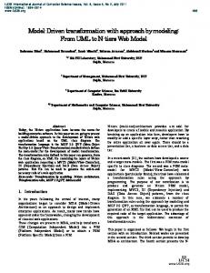
Figure 2.1: The four layer meta-modeling architecture
XSD Schema S1
XSD Schema S2 conformsTo
XML Document describedBy
Data
2.2 Models and Meta-models
9
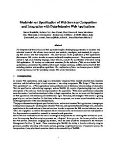
Figure 2.2: MDA based development Process
understood by computers and can be automatically manipulated. In this scenario meta-modeling play a key role. It is intended as a common technique for defining the abstract syntax of models and the interrelationships between model elements. Meta-modeling can be seen as the construction of a collection of “concepts” (things, terms, etc.) within a certain domain. A model is an abstraction of phenomena in the real world, and a meta-model is yet another abstraction, highlighting properties of the model itself. This model is said to conform to its meta-model like a program conforms to the grammar of the programming language in which it is written [12]. In this respect, OMG has introduced the four-level architecture illustrated in Fig. 2.1. At the bottom level, the M0 layer is the real system. A model represents this system at level M1. This model conforms to its meta-model defined at level M2 and the meta-model itself conforms to the metametamodel at level M3. The metametamodel conforms to itself. OMG has proposed MOF [96] as a standard for specifying meta-models. For example, the UML meta-model is defined in terms of MOF. A supporting standard of MOF is XMI [94], which defines an XML-based exchange format for models on the M3, M2, or M1 layer. This metamodeling architecture is common to other technological spaces as discussed by Kurtev et al. in [6]. For example, the organization of programming languages and the relationships between XML documents and XML schemas follow the same principles described above (see Fig. 2.1). In addition to metamodeling, model transformation is also a central operation in MDA as depicted in Fig. 2.2. According to the figure, the development of a software system starts by building a PIM of that system. Then the PIM is refined and transformed to one or more PSMs. Finally, the PSMs are transformed to code. In this way, MDA allows to preserve the investments in business logic since, being a PIM totally unrelated to any specific technology, it is possible to map it to different platforms by means of (semi)automatic transformations which can be defined according specific needs. Achieving this goal would enable analysts to focus only on the design, the business logic, and the overarching architecture. While technologies such as MOF [96] and UML [59] are well-established foundations on which to build PIMs and PSMs, there is as yet no well-established foundation on which to rely in describing how we take a PIM and transform it to produce a PSM. In the next section more insights about model transformations are given and after a brief discussion about the general approaches, the attention focuses on some of the today’s available languages.
10
Chapter 2. Basic Concepts
Figure 2.3: Basic Concepts of Model Transformation
2.3
M ODEL T RANSFORMATIONS
The MDA guide [95] defines a model transformation as “the process of converting one model to another model of the same system”. Kleppe et al. [74] defines a transformation as the automatic generation of a target model from a source model, according to a transformation definition. A transformation definition is a set of transformation rules that together describe how a model in the source language can be transformed to a model in the target language. A transformation rule is a description of how one or more constructs in the source language can be transformed to one or more constructs in the target language. Rephrasing these definitions by considering Fig. 2.3, a model transformation programs take as input a model conforming to a given source meta-model and produces as output another model conforming to a target meta-model. The transformation program, composed of a set of rules, should itself considered as a model. As a consequence, it is based on a corresponding meta-model, that is an abstract definition of the used transformation language. Many languages and tools have been proposed to specify and execute transformation programs. In 2002 OMG issued the Query/View/Transformation request for proposal [93] to define a standard transformation language. Even though a final specification has been adopted at the end of 2005, the area of model transformation continues to be a subject of intense research. Over the last years, in parallel to the OMG process a number of model transformation approaches have been proposed both from academia and industry. The paradigms, constructs, modeling approaches, tool support distinguish the proposals each of them with a certain suitability for a certain set of problems. In the following, a classification of the today’s model transformation approaches is briefly reported, then some of the available model transformation languages are separately described. The classification is mainly based upon [34] and [117].
2.3.1
C LASSIFICATION
At top level, model transformation approaches can be distinguished between model-to-code and model-to-model. The distinction is that, while a model-to-model transformation creates its target as a model which conforms to the target meta-model, the target of a model-to-text transformation
2.3 Model Transformations
11
is essentially strings. In the following some classifications of model-to-model transformation languages discussed in [34] are described. Direct manipulation approach. It offers an internal model representation and some APIs to manipulate it. It is usually implemented as an object oriented framework, which may also provide some minimal infrastructure. Users have to implement transformation rules, scheduling, tracing and other facilities, mostly from the beginning in a programming language. Operational approach. It is similar to direct manipulation but offers more dedicated support for model transformation. A typical solution in this category is to extend the utilized meta-modeling formalism with facilities for expressing computations. An example would be to extend a query language such as OCL with imperative constructs. Examples of systems in this category are QVT Operational mappings [97], XMF [128], MTL [123] and Kermeta [88]. Relational approach. It groups declarative approaches in which the main concept is mathematical relations. In general, relational approaches can be seen as a form of constraint solving. The basic idea is to specify the relations among source and target element type using constraints that in general are nonexecutable. However, declarative constraints can be given executable semantics, such as in logic programming where predicates can be used to describe the relations. All of the relational approaches are side-effect free and, in contrast to the imperative direct manipulation approaches, create target elements implicitly. Relational approaches can naturally support multidirectional rules. They sometimes also provide backtracking. Most relational approaches require strict separation between source and target models, that is, they do not allow in-place update. Example of relational approaches are QVT Relations [97] and AMW [82]. Moreover, in [57] the application of logic programming has been explored for the purpose. Finally, in [31] we have investigated the application of the Answer Set Programming [56] for specifying relational and bidirectional transformations. Hybrid approach. It combines different techniques from the previous categories, like ATL [70] that wraps imperative bodies inside declarative statements. Graph-transformation based approaches. It draws on the theoretical work on graph tranformations. Describing a model transformation by graph transformation, the source and target models have to be given as graphs. Performing model transformation by graph transformation means to take the abstract syntax graph of a model, and to transform it according to certain transformation rules. The result is the syntax graph of the target model. Being more precise, graph transformation rules have an LHS and an RHS graph pattern. The LHS pattern is matched in the model being transformed and replaced by the RHS pattern in place. In particular, LHR represents the pre-condition of the given rule, while RHS describes the postconditions. LHR∩RHS defines a part which has to exist to apply the rule, but which is not changed. LHS − LHS ∩ RHS defines the part which shall be deleted, and RHS − LHS ∩ RHS defines the part to be created. The LHS often contains conditions in addition to the LHS pattern, for example, negative conditions. Some additional logic is needed to compute target attribute values such as element names. AGG [116] and AToM3 [36] are systems directly implementing the theoretical approach to attributed graphs and transformations on such graphs. They have built-in fixpoint scheduling with non-deterministic rule selection and concurrent application to all matching locations, and the rely on implicit scheduling by the user. The transformation rules are unidirectional and in-place. Systems such as VIATRA2 [122] and GReAT [4] extend the basic functionality
12
Chapter 2. Basic Concepts
Figure 2.4: QVT Architecture of AGG and AToM3 by adding explicit scheduling. VIATRA2 users can build state machines to schedule transformation rules whereas GReAT relies on data-flow graph.
2.3.2
L ANGUAGES
In this section some of the languages referred above are singularly described. The purpose of the description is to provide the reader with the background needed to understand the comparison between the approach provided in Chap. 4 with QVT, AGG, ATL, GReAT, and VIATRA2. QVT In 2002 OMG issued the QVT RFP [93] describing the requirements of a standard language for the specification of model queries, views, and transformations according to the following definitions: • A query is an expression that is evaluated over a model. The result of a query is one or more instances of types defined in the source model, or defined by the query language. For example, a query over a UML model might be: Return all packages that do not contain any child packages. The result would be a collection of instances of the Package metaclass. As it will be explained in the following, the Object Constraint Language (OCL 2.0) [98] is the query language actually used in QVT; • A view is a model which is completely derived from a base model. A view cannot be modified separately from the model from which it is derived and changes to the base model cause corresponding changes to the view. If changes are permitted to the view then they modify the source model directly. The meta-model of the view is typically not the same as the meta-model of the source. A query is a restricted kind of view. Finally, views are generated via transformations; • A transformation generates a target model from a source one. If the source and target meta-models are identical the transformation is called endogeneous. If they are different the transformation is called exogeneous. A model transformation may also have several source models and several target models. A view is a restricted kind of transformation in which the target model cannot be modified independently of the source model. If a view is editable, the corresponding transformation must be bidirectional in order to reflect the changes back to the source model. Over the last three years a number of research groups have been involved in the definition of QVT whose final specification has been reached at the end of November 2005 [97]. The abstract syntax of QVT is defined in terms of MOF 2.0 metamodel. This metamodel defines three sublanguages
2.3 Model Transformations
13
for transforming models. OCL 2.0 is used for querying models. Creation of views on models is not addressed in the proposal. The QVT specification has a hybrid declarative/imperative nature, with the declarative that forms the framework for the execution semantics of the imperative part. The layers of the declarative part are the following: • A user-friendly Relations metamodel and language which supports complex object pattern matching and object template creation. Traces between model elements involved in a transformation are created implicitly; • A Core metamodel and language defined using minimal extensions to EMOF and OCL. All trace classes are explicitly defined as MOF models, and trace instance creation and deletion is defined in the same way as the creation and deletion of any other object. By referring to [97], a relation is a declarative specification of the relationships between MOF models. The Relations language supports complex object pattern matching, and implicitly creates trace classes and their instances to record what occurred during a transformation execution. Relations can assert that other relations also hold between particular model elements matched by their patterns. Finally, Relations language has a graphical syntax. Concerning the Core it is a small model/language which only supports pattern matching over a flat set of variables by evaluating conditions over those variables against a set of models. It treats all of the model elements of source, target and trace models symmetrically. It is equally powerful to the Relations language, and because of its relative simplicity, its semantics can be defined more simply, although transformation descriptions described using the Core are therefore more verbose. In addition, the trace models must be explicitly defined, and are not deduced from the transformation description, as is the case with Relations. The core model may be implemented directly, or simply used as a reference for the semantics of Relations, which are mapped to the Core, using the transformation language itself. To better clarify the conceptual link between Relations and Core languages, an analogy can be drawn with the Java architecture, where the Core language is like Java Byte Code and the Core semantics is like the behavior specification for the Java Virtual Machine. The Relations language plays the role of the Java language, and the standard transformation from Relations to Core is like the specification of a Java Compiler which produces Byte Code. Sometimes it is difficult to provide a complete declarative solution to a given transformation problem. To address this issue QVT proposes two mechanisms for extending the declarative languages Relations and Core: a third language called Operational Mappings and a mechanism for invoking transformation functionality implemented in an arbitrary language (Black Box). The Operational Mappings language is specified as a standard way of providing imperative implementations. It provides OCL extensions with side effects that allow a more procedural style, and a concrete syntax that looks familiar to imperative programmers. A transformation entirely written using Operation Mappings is called an “operational transformation”. The Black Box mechanism makes possible to “plug-in” and execute external code. This permits to implement complex algorithms in any programming language, and reuse already available li-
14
Chapter 2. Basic Concepts
braries. However, this mechanism allows implementations of some parts of a transformation to be opaque. ATL ATL (ATLAS Transformation Language) [70] is a hybrid model transformation language containing a mixture of declarative and imperative constructs. The former allows to deal with simple model transformations, while the imperative part helps in coping with transformation of higher complexity. ATL transformations are unidirectional, operating on read-only source models and producing write-only target models. During the execution of a transformation source models may be navigated but changes are not allowed. Target models cannot be navigated. Transformation definitions in ATL form modules. A module contains a mandatory header section, import section, and a number of helpers and transformation rules. Header section gives the name of a transformation module and declares the source and target models (lines 1-2, Fig. 2.5). The source and target models are typed by their meta-models. The keyword create indicates the target model, whereas the keyword from indicates the source model. In the example of Fig. 2.5 the target model bound to the variable OUT is created from the source model IN. The source and target meta-models, to which the source and target model conform, are PetriNet and PNML [19] respectively. Helpers and transformation rules are the constructs used to specify the transformation functionality. Declarative ATL rules are called matched rules. They specify relations between source 1 2 3 4 5 6 7 8 9 10 11 12 13 14 15 16 17 18 19 20 21 22 23
module PetriNet2PNML; create OUT : PNML from IN : PetriNet; ... rule Place { from e : PetriNet!Place --(guard) to n : PNML!Place ( name with Query declaratively defined as first–order logic predicates over finite universes containing model element representatives and Transformation procedurally expressed as parallel updates of the encoding algebra. The transformation branch may contain further transformation rules of the same form. Rules are iteratively fired until they do not cause any further update depending whether their queries have a non empty outcome or not. Thus, the matching algorithm is implicitly defined by the queries which establish also their relative precedences.
4.2
M ODEL AND M ETAMODEL ENCODING
The signature of an algebra encoding a model is canonically induced by the corresponding metamodel whose elements define sorts and functions as in the example of Fig. 4.2 where a simplified UML metamodel is depicted. According to this metamodel classes have name, a set of attributes and they can be declared as persistent (see the meta attribute isPersistent). An attribute has a name, a type and can be defined as primary (see isPrimary). Finally, classes can be related by means of binary associations and can be hierarchically organized. This metamodel induces the signature Σ (on the right-hand side of the figure) composed of sorts (S) and functions (OP ). In particular, for each meta class of the metamodel a correspondent set in
4.3 Model Transformation Rules
33
Σ = (S, OP ) S := {Class, Classif ier, Attribute, P ackage, P rimitiveDataT ype, Association} OP := name : Classif ier → String name : Attribute → String name : P ackage → String name : Association → String source : Association → Class target : Association → Class isP ersistent : Class → Bool isP rimary : Attribute → Bool elems : (P ackage, Class) → Bool attrs : (Class, Attribute) → Bool belong : (Class, Attribute) → Bool type : Attribute → Classif ier parent : Class → Class
Figure 4.2: Algebraic encoding of a sample UML metamodel S is available. Functions are induced by meta attributes, meta associations, and roles. For example, the attribute name of Classifier induces the definition of the function name: Classifier → String. In order to specify the type of an Attribute, the function type: Attribute → Classifier is defined with respect to the role type of the meta class Classifier in the meta association with the meta class Attribute. Multiple meta associations are encoded by means of relations1 . For example, a given class can have a number of attributes as stated by the role attrs of the meta association between Class and Attribute meta classes. In this case the relation attrs in OP will be provided and it will be true if an attribute belongs to a given class, false otherwise. Meta associations which are compositions induce the definition of the relation belong. For instance, in the case of the composition between Class and Attribute, the relation belong: (Class, Attribute) → Bool is defined which is true for each couple (c,a) such that attrs(c,a)=true. The approach permits the encoding of specializations in the metamodels by means of sub-sorting. For instance, the inheritances between Class and Classifier and between PrimitiveDataType and Classifier is encoded by means of the following sub-sorting relation: Class < Classifier and PrimitiveDataType < Classifier. The sets and the functions induced by a metamodel are used for encoding models that conform to the given metamodel as in Fig. 4.3 where the encoding of a sample UML model is depicted. In particular, on the lower-side of the figure the sets and the functions defined in Fig. 4.2 are updated according to the UML model on the upper-side of the figure. The canonical encoding of metamodels and models can be performed in an automatic way as discussed in [37].
4.3
M ODEL T RANSFORMATION RULES
In this section, in order to better clarify the approach depicted in Fig. 4.1 and the overall structure of an A4MT transformation specification, the standard class diagram to relational data base 1
Relations are special cases of functions whose value can be true or false.
34
Chapter 4. ASMs for Model Transformation Specification (A4MT)
name(c1 ) = “P erson” name(c2 ) = “Address” name(c3 ) = “Data”
... name(p1 ) = “Int” name(a1 ) = “name” name(a2 ) = “birthday” type(a2 ) = c3 name(a3 ) = “cust id” type(a3 ) = p1
... source(ass1 ) = c1 target(ass1 ) = c2
... attributes(c1 , a1 ) = true attributes(c1 , a2 ) = true attributes(c1 , a3 ) = true
... Figure 4.3: Algebraic encoding fragment of a Sample UML model
(UML2RDBMS) case study described in [18] is specified. The involved source and target metamodels are depicted in Fig. 4.2 and Fig. 4.4 respectively. The main requirements of the transformation are recalled in the following even if the reader can refer to [18] for more details. Classes can be indicated as persistent or non-persistent. A persistent class is mapped to a table and all its attributes or associations to columns in this table. If the type of an attribute or association is another persistent class, a foreign key to the corresponding table is established. In case of class hierarchies, only the topmost classes are mapped to tables. Additional attributes and associations of subclasses result in additional columns of the top-most classes. Non-persistent classes are not mapped to tables. However, one of the main requirements of the transformation is to preserve all the information of the source class diagram. That means attributes and associations of non-persistent classes have to be distributed over those tables stemming from persistent classes which access non-persistent classes. To summarize the requirements of the UML2RDBMS transformation that will be specified are the following:
4.3 Model Transformation Rules
35
Figure 4.4: Sample RDBMS metamodel 1. Persistent classes that are roots of an inheritance hierarchy are transformed to tables. In particular, in inheritance hierarchies, only the top most parent class should be converted into a table; the resultant table should however contain the merged columns from all its subclasses. For example, from the classes in Fig. 4.5, only the tables T Person and T Phone will be generated (see Fig. 4.6). Furthermore, the transformed attributes of the class Customer will be placed in the table T Person; 2. Each attribute of a primitive type is transformed to a single column. If the attribute is primary, a primary column in the corresponding table is generated like the attributes name and number in Fig. 4.5 that give place to the primary keys of the generated table T Person and T Phone respectively (see Fig. 4.6); 3. Attributes whose type is a non-persistent class and associations that point to such a class are transformed to a set of columns derived from the class itself. This is applied recursively until a set of primitive attributes is obtained. Circularity in references to classes is not allowed here. For example, the type of the attribute birthday of the class Person will give place to the columns birthday day, birthday month and birthday year in the table T Person derived from the attributes of the source non-persistent class Data; 4. Attribute whose type is a persistent class and associations that point to such a class are transformed to a foreign key and a set of columns contained in that key. The foreign key refers to the table derived from the persistent class. The columns are derived from the primary attributes of the persistent class. For instance, the address association from the Person class will induce the generation of the columns address addr and address phone number in T Person. The latter is a foreign key that refers to T Phone; In the following, these transformation requirements will be formally specified by means of the A4MT. In order to better clarify the approach, the solution is presented in two steps. In the first one only persistent classes will be taken into account. Thereafter, a complete solution will be discussed by satisfying all the transformation requirements. In developing model transformations, the designer specifies how to generate target models from source ones. The generation is based on relationships between the involved metamodels and it can be based on simple correspondences or it could require complex computations on the models. In A4MT a model transformation specification consists of one or more rules having the following form:
36
1 2
Chapter 4. ASMs for Model Transformation Specification (A4MT)
--Query do forall IN_PATTERN
3 4 5
--Transformation OUT_PATTERN
6 7
enddo
where a query on the source model encoding is performed to find all the matches of the input pattern (IN PATTERN). A pattern is a specification of source type coming from the source metamodel and it can be decorated with conditions that drive the searching of matches on the source models. In the proposed approach, a query is expressed by means of first-order logic predicates and for each of the matched pattern, the encoding of the target model is modified by changing the population of universes and the point-wise definitions of functions, as procedurally specified by the OUT PATTERN. This one could embed the specifications of further transformation rules which will be executed until the query of the outermost one succeeds and no more changes on the algebra occur. Taking into account this general form of a transformation rule, a Class2Table rule can be given to specify how the classes in a source UML model have to be transformed to tables in the target RDBMS model according to the UML2RDBMS transformation requirements given above. Essentially, each persistent class in the source model induces a table in the target one. The name of the generated table is the name of the source class prefixed with the string "T ". In this case, the IN PATTERN consists of a persistent class description that is an element c belonging to the universe Class on which the function isPersistent (induced by the source metamodel) is true. The OUT PATTERN definition is based on the ASM extend construct used to specify the extension of the universes and the update of the functions induced by the target metamodel (like for example the universe Table and the function name). 1 2 3
--Rule Class2Table --IN_PATTERN do forall c in Class : isPersistent(c)
4 5 6 7 8 9
--OUT_PATTERN extend Table with t name(t):="T_"+name(c) transformed(c):=t endextend
10 11
enddo
During the specification of transformation rules the designer could have the need to maintain traceability information in order to relate representatives of target elements with source one. Specific functions can be defined for this purpose like transformed in the sample rule that for each class that has been transformed, maintains the reference to the corresponding generated table. The use of “trace link” functions like this is clarified in the following rule which specifies the transformation of class attributes into table columns. In particular, the IN PATTERN of the Attribute2Column rule is more intricate of the previous one since it specifies attributes which are of primitive type, non primary key, and which belong to already transformed classes. The specification of this pattern exploits the ASM choose construct used to select the attributes satisfying these requirements and that belong to classes on which the function transformed is true (line 4). If the choose succeeds new columns are generated (see line 6-11) and the proper function updates occur. The generated columns are specified as belonging to the table corresponding to the persistent class selected through the choose rule. The relation cols induced by the target metamodel is used for
4.3 Model Transformation Rules
37
(a) Class Diagram
(b) Class Diargam as Metamodel-Instance
Figure 4.5: Sample Source UML Model this purpose. In particular, given a table t and a column c, col(t,c) is true if c is a column of the table t (see the model in Fig 4.6.b). 1 2 3 4
--Rule Attribute2Column --IN_PATTERN do forall a in Attribute choose c in Class : attrs(c,a) and transformed(c)!=undef and isPrimitiveDataType(type (a)) and not(isPrimary(a))
5 6 7 8 9 10 11
--OUT_PATTERN extend Columns with col name(col):=name(a) type(col):=type(a) cols(transformed(c),col):=true endextend
12 13 14
endchoose enddo
38
Chapter 4. ASMs for Model Transformation Specification (A4MT)
(a) Data Model
(b) Data Model as Metamodel-Instance
Figure 4.6: Sample Target RDBMS Model In case of attributes which are defined as primary, the corresponding generated columns have to be specified as part of the primary key of the table to which they will belong. The rule PrimaryAttribute2PrimaryKeyColumn is devoted to perform this transformation. Even though this rule is logically distinct from Attribute2Column, the OUT PATTERN descriptions differ for the update of the function pkey only (see line 11 below). 1 2 3 4
--Rule PrimaryAttribute2PrimaryKeyColumn --IN_PATTERN do forall a in Attribute choose c in Class : attrs(c,a) and transformed(c)!=undef and isPrimitiveDataType(type (a)) and isPrimary(a)
5 6 7 8 9 10 11 12
--OUT_PATTERN extend Columns with col name(col):=name(a) type(col):=type(a) cols(transformed(c),col):=true pkey(transformed(c),col):=true endextend
13 14 15
endchoose enddo
In cases like this the designer may adopt optimizations based on rule merging. For instance, in the running example only the Attribute2Column rule could be maintained by removing the term not(isPrimary(a)) in the guard of the choose rule and by adding the following condition in the OUT PATTERN specification:
4.3 Model Transformation Rules
1 2 3
39
if isPrimary(a) then pkey(transformed(c),c):=true endif
However, even though this kind of optimizations could reduce the length of the specifications, we believe that in general they should be avoided especially when the readability, reuse and maintenance of rules could be compromised. Generally, model transformation rules, given a matched input pattern, produce more than one single target element contrarily to the rules provided until now. For instance, according to the requirements of the UML2RDBMS transformation, each attribute with a persistent class as type, gives place to a set of columns contained by the key of the pointed persistent class, and a foreign key referring to the table derived from the persistent class where the source attribute belongs. The specification of this more intricate OUT PATTERN is given in the following Attribute2ForeignKey rule. In particular, for each attribute a having as type a persistent class and belonging to an already transformed class (see lines 3-4) the given output pattern has to be applied. For each primary column (col) belonging to the table generated from the persistent class which is the type of the attribute a (see line 6), a new column for the table pointed by transformed(c) is created and the corresponding foreign key is also updated (lines 11-15). 1 2 3 4
--Rule Attribute2ForeignKey --IN_PATTERN do forall a in Attribute choose c in Class: attrs(c,a) and transformed(c)!=undef and isPersistent(type(a)) and not(isPrimitiveDataType(type(a)))
5 6 7 8 9 10 11 12 13 14 15 16
--OUT_PATTERN do forall col in Column : cols(transformed(type(a)), col) and isPrimary(col) extend Column with tc name(tc):=name(a)+"_"+name(col) cols(transformed(c),tc):=true extend FKey with fk references(fk):=transformed(type(a)) cols(fk,tc):=true fkeys(transformed(c),fk):=true endextend endextend
17 18
enddo
19 20 21
endchoose enddo
The transformation of source associations is very similar to the transformation specified in the Attribute2ForeignKey rule. In fact, an association between persistent classes is transformed in the same way as an attribute with a persistent class as type. In the case of an association ass new columns are added in the table pointed by transformed(src(ass)) with respect to the primary key of the table transformed(dest(ass)). Moreover, the new columns will be part of the source table foreign key as specified in the lines 11-15 below 1 2 3 4
--Rule Association2ForeignKey --IN_PATTERN do forall ass in Association choose c in Class: src(ass)=c
and transformed(c)!=undef and isPersistent(dest(ass)))
5 6 7 8 9
--OUT_PATTERN do forall col in Column : cols(transformed(dest(ass)), col) and isPrimary(col) extend Column with tc name(tc):=name(ass)+"_"+name(col)
40
10 11 12 13 14 15 16
Chapter 4. ASMs for Model Transformation Specification (A4MT)
cols(transformed(c),tc):=true extend FKey with fk references(fk):=transformed(dest(ass)) cols(fk,tc):=true fkeys(transformed(c),fk):=true endextend endextend
17 18
enddo
19 20 21
endchoose enddo
The complete UML2RDBMS model transformation is an extension of the presented basic solution which takes into account also class inheritance and non-persistent classes. As required, in class hierarchies only the top-most classes are mapped to tables. However, one of the main requirements for the considered model transformation is the preservation of all the information in the class diagram. The specification of the transformation satisfying these further requirements is based on the concept of transitive closures of the class inheritance and association relations according to the following definitions. Definition 15 The transitive closure TCI of the inheritance relation inherit from a top class c is defined as follows:
TCI(c) =
[
ci
ci ∈Class : inherit(c,ci )
where the relation inherit(c, ci ) is true if exists a path of inheritances that connect c with ci . Definition 16 The transitive closure TCA of the association relation npassoc from a class c is defined as follows:
TCA(c) =
[
assi
assi ∈Association : npassoc(c,ass)
where the relation npassoc(c, assi ) is true if exists a path of associations that permits to reach the association assi from the class c. A4MT transformations which need complex computations on the source model like the calculation of transitive closures defined above, can exploit asynchronous and recursive ASMs sub-machines devoted to perform such computations without side-effects. This is one of the characteristics that mainly distinguish A4MT from graph transformation approaches. In fact, differently to them, A4MT do not “paint” the models with information only needed for the calculation. Furthermore, such approaches need to polish the source models once the transformation has been performed. Nor this operation is required by A4MT as it will be clarified in the following. In the running example, the computation of the transitive closure of the inheritance relation is performed by the sub-machine calculateTCI that takes a top class as input and iteratively updates the
4.3 Model Transformation Rules
41
function inherit. As explained in Chapter 3 an ASM machine is executed until no more changes occur on the algebra. This explains the use of the choose rule in calculateTCI; once the initialization inherit(top,top):=true is performed, the rule in line 9 below is executed until the guard of the choose become false. In each iteration the rule searches for a new class c which is not in the transitive closure of the top class yet but that has to be added since exists a class subC in current transitive closure which is parent of the considered class c. 1 2 3 4 5 6 7
--Transitive closure computation of class inheritance asm calculateTCI(top:Class) ... is init inherit(top,top):=true endinit
8 9 10 11 12 13 14 15
choose c in Class:( inherit(top,c)=undef and exists subC in Class: inherit(top,subC) and parent(c)=subC ) inherit(top,c):=true endchoose ... endasm
The transitive closure of the association relation is calculated by means of the calculateTCA submachine which is very similar to calculateTCI. In fact, apart from the initialization step, the implemented logic is the same. In each iteration, an association ass in the set Association is selected whether it is not in the current transitive closure maintained by the relation npassoc and if exists another association nearAss for which npassoc(top,nearAss) is true and the destination class of nearAss is the source of the association ass. 1 2 3 4
--Transitive closure computation of association relation asm calculateTCA(top:Class) ... is
5 6 7 8 9 10 11 12 13
init do forall ass in Association if (src(ass)=top) then npassoc(top,ass):=true ... endif enddo endinit
14 15 16 17 18 19
choose ass in Association :( (npassoc(top,ass)=undef) and (existsnearAss in Association : ( npassoc(top,nearAss)) and (dest(nearAss)=src(ass))) ) npassoc(top,ass):=true ... endchoose
20 21
endasm
Th commonalities between the two sub-machines permit the definition of a generic one able to deal with the problem of the transitive closure in general, independently from the relation which has to be considered. 1 2 3 4 5
--Generic transitive closure computation asm calculateTC(se:_, set:String, relation:String, condition:String ) ... is
42
6 7 8 9 10 11
Chapter 4. ASMs for Model Transformation Specification (A4MT)
choose element in $set$ :( ($relation$(se,element)=undef) and (exists nearElement in $set$ : ($tc$(se,nearElement)) and ($condition$)) ) $relation$(se,element):=true ... endchoose
12 13
endasm
The calculateTC sub-machine is a tentative implementation of a generic transitive closure calculation. The input parameters of the sub-machine are the following: – se: it is the element on which the transitive closure is calculated. In the case of TCI and TCA defined above, se corresponds to the element c of the definitions; – set: it is the name of the universe where the elements have to be selected in each iteration. For the calculateTCI and calculateTCA sub-machine, the set string refer to the universes Class and Association respectively; – relation: it is the name of the relation in which respect the transitive closure is calculated; inherit and npassoc are the relations on which the transitive closure computations calculateTCI and calculateTCA are based respectively; – condition: it describes when a new element should be added in the transitive closure being calculated. In the case of the inheritance relation, a new class c1 can be added if a exists an other class c2 , already in the transitive closure, such that parent(c1 ) = c2 . In the case of the association relation, a new association ass1 can be added if exists an association ass2 in the transitive closure such that dest(ass2 ) = src(ass1 ). This generic machine is inspired by the concept of generic transformation which has been proposed by Varr´o and Pataricza in [121] where data types, including model element types, are parameters of transformations which result to be more reusable. The described sub-machines devoted to the transitive closure computations enable the complete specification of the UML2RDBMS model transformation by taking into account also class inheritance and non-persistent classes. As required, in class hierarchies, once the top-most classes are mapped to tables, additional attributes and associations given by subclasses have to be merged in the top-most one. Furthermore, attributes or associations pointing to non-persistent classes, give place to columns of the table corresponding to the original persistent class. The following specifications deals with the extended version of the attribute and association transformation. The IN PATTERN of the rules makes use of the inherit function updated by the calculateTCI submachine. For instance, in the AttributeTransformation rule, for each persistent class (c1 ) which is top of a class hierarchy, all the attributes belonging to the subclasses (i.e. classes c2 such that inherit(c1 , c2 ) is true) will be transformed by means of the rules described until now with some minor modifications. For example, concerning the primary attribute transformations, instead of searching the class to which the attribute being transformed belongs, in the PrimaryAttribute2PrimaryKeyColumn’ rule (lines 11-19) for each class c2 in the transitive closure of c1, all the attributes of c2 give place to columns of the table corresponding to the top-most class c1.
4.3 Model Transformation Rules
1
43
--Rule AttributeTransformation
2 3 4 5
--IN_PATTERN do forall c1 in Class : isTop(c1) and isPersistent(c1))) do forall c2 in Class : inherit(c1,c2)
6 7 8 9
--OUT_PATTERN --Attribute2Column’(c1,c2) ...
10 11 12 13 14 15 16 17 18 19
--PrimaryAttribute2PrimaryKeyColumn’(c1,c2) do forall a in Attribute : (attrs(c2,a)) and (isPrimitiveDataType(type(a))) and isPrimary(a) extend Column with col name(col):=name(a) type(col):=type(a) cols(transformed(c1),col):=true pkey(transformed(c1),col):=true endextend; enddo
20 21 22
--Attribute2ForeignKey’(c1,c2) ...
23 24 25
--NonPersAttr2Column(c1,c2) ...
26 27 28
enddo enddo
The rules Attribute2Column’ and Attribute2ForeignKey’ are based on the same principle and for readability reasons their specifications are not provided here. However, the reader can refer to their complete specification available for download at [35]. To better clarify how the transitive closure of the association relation is exploited in the transformation phase, let us consider the example in Fig. 4.5 and Fig. 4.6. For instance, the association address between the source Person and Address classes is translated into the columns address addr and address phone number of the target table T Person. The latter is also a foreign key (referring to the table Phone) which has been added in the table T Person since the class Phone is in the transitive closure of the association relation from the class Person. The AssociationTransformation rule performs such a transformation whose NonPersAttr2Column rule used above is a slight adaptation. The IN PATTERN of AssociationTransformation is the same of the AttributeTransformation rule in order to take into account the associations of all the subclasses of a given top class. The OUT PATTERN is made up in turn by two other transformation rules able to transform both associations with non-persistent and persistent classes. For each class c2 in the transitive closure of c1, these two transformations are iteratively and independently applied until no more matches of their IN PATTERN are found. Concerning the associations in the transitive closure of the given class c2 and targeting to non-persistent classes (line 9), for each attribute of these classes a new column in the table corresponding to the top class c1 has to be generated. 1
--Rule AssociationTransformation
2 3 4 5
--IN_PATTERN do forall c1 in Class : isTop(c) and isPersistent(c1))) do forall c2 in Class : inherit(c1,c2)
6 7
--OUT_PATTERN
8 9 10
--NonPersAssoc2Column --IN_PATTERN
44
11
Chapter 4. ASMs for Model Transformation Specification (A4MT)
do forall ass in Association : (npassoc(c2,ass) and not(isPersistent(dest(ass))))
12
--OUT_PATTERN do forall at in Attribute : (attrs(dest(ass), at) ) extend Column with tc name(tc):=npassocName(c2,ass)+"_"+name(at) cols(transformed(c1),tc):=true type(tc):=type(at) endextend enddo
13 14 15 16 17 18 19 20 21 22
enddo
23 24 25 26
--Association2ForeignKey’ --IN_PATTERN do forall ass in Association : (npassoc(c2,ass) and isPersistent(des(ass2)))
27
--OUT_PATTERN do forall col in Column : (cols(transformed(dest(ass2)),col)) and (isPrimary( col))) extend Column with tc name(tc):=npassocName(c2,ass)+"_"+name(col) type(tc):=type(col) cols(transformed(c),tc):=true extend FKey with fk references(fk):=transformed(dest(ass)) cols(fk,tc):=true fkeys(transformed(c1),fk):=true endextend endextend enddo
28 29 30 31 32 33 34 35 36 37 38 39 40 41 42
enddo
43 44 45
enddo enddo
The name of each new column is the name of the attribute prefixed with a string representing the path from the class c2 to the attribute being transformed (available in the function npassocName which have been updated during the transitive closure computation of the association relation). For instance, the association address in Fig. 4.5.a gives place to the attribute address addr in the table T Person in Fig. 4.6.a. In case of persistent target classes the OUT PATTERN of the Association2ForeignKey’ transformation is applied. In particular, each primary key of the table corresponding to the target class c2 gives place to a new column in the table obtained from the class c1 and to a new foreign key referring to the table corresponding to the class c2. For instance the association phone reachable from the class Person through the association address gives place to the column address phone number in the table T Person. The foreign key of this table is also updated (see lines 34-38) to obtain the final model in Fig. 4.6. In the next section, A4MT is collocated in the context of the QVT RFP (Request For Proposal) [93] issued by the OMG in 2002 in order to specify the requirements that a transformation language in a MDA setting should address. Then a comparison between A4MT and the approaches presented in Sec. 2.3.2 is provided.
4.4 A4MT in the context of MOF 2.0 QVT RFP
4.4
45
A4MT IN THE CONTEXT OF MOF 2.0 QVT RFP
QVT RFP addresses the need for a standard language for transformation definitions in MDA. It states a set of mandatory and a set of optional requirements that QVT compliant languages should address. In this section a summary of these requirements is provided and how A4MT satisfies with them is also presented according to [77]. QVT Mandatory Requirements • Query language: proposals should define a language for querying models; • Transformation language: proposals should define a language for expressing transformation definitions. Transformation definitions are executed over MOF models, i.e. models that are instances of MOF meta-models; • Abstract syntax definition: QVT languages should define their abstract syntax as a MOF meta-model; • View language: QVT languages should enable creation of views on models; • Declarative language: proposals should define declarative transformation language; QVT Optional Requirements • Bidirectional transformation definitions: proposals may support transformation definitions executable in two directions; • Traceability: proposals may support generation of traceability information; • Reuse mechanisms: QVT languages may support mechanisms for reuse and extension of generic transformation definitions; • Transactional transformations: proposals may support execution of parts of transformations as a transaction; • Update of existing models: proposals may support execution of transformations where the source and the target model are the same; It is possible to evaluate A4MT against the QVT requirements giving place to the Table 4.4. Concerning the mandatory requirements, A4MT provides with a query language based on first-order logic. In fact, as shown in the UML2RDBMS example discussed above, first-order logic predicates are used to express query. The transformations are expressed by using the ASMs constructs whose MOF-based metamodel is available [102]. This permits to satisfy the second and the third mandatory requirements. A view language is not directly provided even though a view can be obtained by means of queries and transformations (see QVT in Sec. 2.3.2). Concerning the last mandatory requirement, A4MT does not provide a pure declarative transformation language even if the approach can be considered hybrid. In fact, models are queried in a declarative way and transformations are procedurally expressed. Concerning the optional requirements, A4MT addresses most of them. For example, a traceability support is provided (as better described in the next section). Transformation rules can be embodied
46
Chapter 4. ASMs for Model Transformation Specification (A4MT)
QVT Requirement
Support by A4MT
Query Language
First-order logic predicates are used to query models
Transformation language working on MOF models
The approach is capable of expressing transformations on MOF models even though it supports transformation scenarios not addressed in QVT
Abstract syntax definition
A MOF metamodel of ASMs is available [102]
View language
Not available
Declarative transformation language
The approach is hybrid in the sense that models are queried in a declarative way and transformations are procedurally expressed
Bidirectional transformations
Only unidirectional transformations are supported
Traceability support
Available
Reuse and extension mechanisms
The approach provides with sub-machine facilities enabling transformation libraries
Transactional transformations
Not available
Update of models
Available
Table 4.1: Support of the QVT requirements by A4MT in sub-machines that other rules can invoke providing a modularity mechanism. However, the use of sub-machines is suggested to perform complex computations or navigation on models without side effects or to define libraries that can be reused in different transformations (the sub-machines proposed above for the transitive closure computations are an example). In place transformations are also supported by A4MT (this aspect will be better addressed in the next section) whereas transactional transformations are not supported yet. Finally, A4MT permits the specification of unidirectional transformation in contrast with the first optional QVT requirement.
4.5
C OMPARING A4MT WITH OTHER A PPROACHES
In this section, A4MT is classified with respect to the major features provided by Czarnecki and Helsen in [34] where they present a domain analysis of existing model transformation approaches. In the following, some of the main features are described and considered for classifying A4MT and comparing it with the transformation approaches presented in Sec. 2.3.2. The comparison is presented also in Table 4.5.
4.5 Comparing A4MT with other Approaches
47
Paradigm. This feature refers to the programming paradigm used to define transformations. It can be mainly distinguished between imperative, declarative and hybrid. A4MT can be classified as a hybrid approach since transformation rules have a query which is declaratively defined as first–order logic predicates over finite universes containing model element representatives, and a transformation part which is procedurally expressed as parallel updates of the encoding algebra. In this sense, the approach is similar to ATL, VIATRA2 and GReAT. In fact, ATL wraps imperative bodies inside declarative shells. VIATRA2 and GReAT have a declarative rule language based on graphs and an imperative language for rule application order. In VIATRA2, Abstract State Machines are used for this purpose. AGG is a pure declarative approach which does not permit the specification of imperative transformation statements. Finally, QVT-Relations and QVT-Core, even though at two different level of abstractions, are two declarative languages differently to QVT-OM which is an imperative one. Directionality. Transformations may be unidirectional or multidirectional. Unidirectional transformations map the source metamodel into the target metamodel but not the converse. Although this may appear a limitation, in practical cases this is essentially unavoidable since a multidirectional transformation, that can be executed in multiple directions, could implies the adoption of declarative rule-based formalisms that pose severe questions about the termination of transformations [119]. Multidirectional transformations are particularly useful in the context of model synchronization and can be achieved also by defining several separate complementary unidirectional rules, one for each direction. A4MT permits the specification of unidirectional transformation like the other considered transformation languages except QVT-Relations which supports also multidirectional rules. Cardinality. It indicates the number of input and output models involved in a transformation definition. A4MT permits the definition of transformation rules able to query multiple source models and eventually generate elements in different target one. This is feasible by means of an encoding phase that permits to maintain the involved models separated. For such a purpose name conventions or auxiliary functions can be used. If the encoding is properly performed, the transformation rules can be normally expressed as described in the previous section. The unique distinctive characteristic is the way the patterns are written. In particular, the IN PATTERN are first-order predicates defined by means of terms coming from the signatures of different source metamodels. In the same way, the OUT PATTERN extends universes and updates functions encoding different target models. Except AGG which supports 1-to-1 transformations, the other considered approaches permit the specification of M-to-N transformations. Traceability. Traceability links connect source and target elements which are essentially instances of the mappings between the source and target domains. Traceability links can be established by storing the transformation rule and the source elements that were involved in creating a given target element. Traceability links can be automatic or user-defined. In the former case, the execution engine is encharged to create and update the data structures devoted to store traceability links. In the latter the transformation designer is responsible to do this. The availability of traceability distinguishes a transformation between persistent and stateless. The former enables change propagation, in the sense that performing the transformation when the source model has changed does not always result in a newly creation model. In fact, persistence implies version policies towards the target model that in combination with the trace information allows not to rewrite completely the target model for different incarnations of the transformation.
48
Chapter 4. ASMs for Model Transformation Specification (A4MT)
In A4MT the traceability is user-defined. For example, in the UML2RDBMS example discussed above, the transformation designer uses the function transformed to maintain the information from which source class a target table has been generated. More complex traceability structures can be defined even though the transformation designer is encharged to use them in the transformation rule specifications. ATL, QVT-OM and QVT-Relation provide with dedicated support for tracing, and traceability links are created automatically. Even without dedicated support, in the case of AGG, GReAT, VIATRA2 and QVT-Core, tracing information can always be created just as any other target element. Moreover, AGG and VIATRA2 rely on traceability links to prevent multiple “firings” of a rule for the same input element. Query Language. A transformation approach provides a mean to select elements from the source models to be considered in the transformation phase. A4MT exploits the first-order logic to query models in a declarative way. ATL and QVT-OM have a query language based on OCL. The other approaches rely on the concept of pattern intended as a collection of model elements arranged into a certain structure fulfilling additional constraints (as defined by attribute conditions or other patterns). VIATRA2, GReAT and AGG express queries by means of graph patterns whereas QVTRelation and QVT-Core supports object patterns. Rule Application Strategy. It is the strategy for determining the model locations to which transformation rules are applied. In particular, a rule needs to be applied to a specific location within its source scope. As there may be more than one match for a rule within a given source scope, a strategy for determining the application locations is needed. The strategy could be deterministic, nondeterministic, or interactive. Example of nondeterministic strategies include one-point application, where a rule is applied to one non-deterministically selected location, and concurrent location, where one rule is applied concurrently to all matching locations in the source. In A4MT the way in which the application locations are determined is nondeterministic and concurrent. Concurrent application is also supported in AGG and VIATRA2, whereas ATL, GReAT and QVT adopt a nondeterministic one-point strategy. Rule Scheduling. Scheduling mechanisms determine the order in which individual transformation rules are applied. A scheduling can be implicit or explicit. The former implies that the user has no explicit control over the scheduling algorithm defined by the tool. The only way a user can influence the system-defined scheduling algorithm is by designing the patterns and logic of the rules to ensure certain execution orders. Explicit scheduling has dedicated constructs to explicitly control the execution order. Furthermore, explicit scheduling can be internal or external. In external scheduling, there is a clear separation between the rules and the scheduling logic. In contrast, internal scheduling is a mechanism allowing a transformation rule to directly invoke other rules. In general, A4MT provides with an implicit scheduling rule. In fact, according to the specified queries, the rules are iteratively and implicitly applied until no more changes on the algebra occur. Moreover, transformation rules can be embodied in sub-machines that other rules can invoke (providing an internal explicit scheduling). However, the use of sub-machines is suggested only to perform complex computations or navigation on models without side effects. The internal scheduling is supported also by ATL (that provides the implicit one too ) and QVTOM, whereas QVT-Relation and QVT-Core provide with an implicit rule scheduling. VIATRA2 and GReAT have a dedicated language for specifying the application order of rules. For example, in VIATRA2 graph transformation is the primary means for elementary model transformation steps which are invoked by using the control flow structures provided by ASMs.
4.6 Conclusions
49
In AGG the rule application order is specified by means of layers and each graph transformation rule is assigned to a certain layer. Starting with layer 0, the rules of one layer are applied as long as possible. Thereafter, the next layer is executed. Having executed the highest layer, the transformation is finished. Rule Organization. Rule organization is concerned with composing and structuring multiple transformation rules. For example, the organization can exploit on modularity and reuse mechanisms based on rule inheritance or packaging to mention a few. A4MT uses the ASMs submachine facilities to specify computations that can be used in different transformation rules. The transitive closure computations discussed in the UML2RDBMS case study is an example. ATL, QVT and VIATRA2 allow packaging rules into modules. A module can import another module to access its content. Moreover, rule inheritance is allowed in ATL and QVT, whereas AGG bases the organization of rules on the layer concept explained above. GReAT rely on rule blocks that provide the means to organize rules into higher-level hierarchies. Within a rule block, rules are chained (and thus sequenced) by passing previously matched elements from rule to rule. Using rule block constructs, a complex transformation can be decomposed into a sequence of simpler rules. Moreover, rule blocks can be arranged into hierarchies of blocks. Source-Target Relationship. This feature concerns the creation of a new target model which can be separate from the source one or not. Some approaches, like ATL, mandate the creation of a new target model that has to be generated from the source. In some other approaches, such as AGG, GReAT and VIATRA2, source and target are always the same model, that is, they only support inplace update. QVT allows creating a new model or updating an existing one even though in-place updates are also supported. Concerning A4MT, transformation rules change algebras which encode both source and target models. However they are maintained separated by means of a proper encoding that permit to apply transformation rules to update the target models, to modify the source ones or both. This means that even though during the application of transformation rules, there is only one algebra, source and target models are maintained distinct.
4.6
C ONCLUSIONS
This chapter proposed A4MT, an Abstract State Machines based approach which makes possible formal and implementation independent specifications of model transformation behaviours. A4MT aims at providing the transformation developers with the possibility to check their basic design decisions against an accurate and executable high-level model of the transformation itself. A canonical encoding of models and metamodels was introduced and the UML2RDBMS model transformation case study (which is standard in the literature) was considered throughout the chapter to highlight explicitly how ASMs can be used to design transformations in general. The chapter shown also how A4MT permits to specify complex computations on models like the calculation of transitive closures with respect to some relations. The chapter tried to give strategies, best practices, design patterns for specifying transformation rules and discussed how models could be navigated and queried by means of first order predicates instead of patterns which are lacking in ASMs.
50
Chapter 4. ASMs for Model Transformation Specification (A4MT)
A4MT was collocated in the context of MOF 2.0 QVT RFP. Most of the mandatory and optional requirements of the request for proposal can be addressed. Finally, the approach was compared with some of today’s available transformation languages even though A4MT aims to be an highlevel specification approach that can be used to design and validate transformation before their actual implementation. In this way the transformation developers can check their implementation written in a specific language like AGG, ATL, QVT, etc. against an accurate and executable highlevel model of the transformation itself given by means of A4MT.
4.6 Conclusions
Category
Table 4.2: Transformation Approach Comparison
A4MT
ATL
VIATRA2
GReAT
AGG
QVT-Relations
QVT-OM
QVT-Core
No Yes Yes
Yes Yes Yes
No Yes No
No Yes No
Yes No No
Yes No No
No No Yes
Yes No No
Query Language
First-order Logic Predicates
OCL based
Graph Pattern
Graph Pattern
Graph Pattern
Object Patter
OCL based
Object Pattern
Rule Scheduling
Implicit, Internal Explicit
Implicit, Internal Explicit
External Explicit
External Explicit
External explicit, Implicit
Implicit
Internal Explicit
Implicit
Sub-machine
Rule Inheritance, Libraries
Rule Packaging
Hierarchy of Rule Blocks
Layering
Rule and Transformation Inheritance
Rule and Transformation Inheritance
Rule and Transformation Inheritance
Nondeterministic (concurrent)
Nondeterministic (one-point)
Nondeterministic (concurrent)
Nondeterministic (one-point)
Nondeterministic (concurrent)
Nondeterministic (one-point)
Nondeterministic (one-point)
Nondeterministic (one-point)
Directionality - Unidirectional - Multidirectional
Yes No
Yes No
Yes No
Yes No
Yes No
No Yes
Yes No
No Yes
Cardinality - M-to-N - 1-to-1
Yes Yes
Yes Yes
Yes Yes
Yes Yes
No Yes
Yes Yes
Yes Yes
Yes Yes
Traceability - Automatic - User-specified
No Yes
Yes No
No Yes
No Yes
No Yes
Yes Yes
Yes Yes
No Yes
Source-Target Relationship - New Model - In-Place
Yes Yes
Yes Yes
No Yes
No Yes
No Yes
Yes Yes
Yes Yes
Yes Yes
Paradigm - Declarative - Hybrid - Imperative
Rule Organization
Rule Application Strategy
51
C HAPTER 5 A4MT B ENCHMARK
A4MT has been validated in different applicative domains and the results are reported in this chapter. Sec. 5.1 discusses the use of A4MT to support the model driven development of data-intensive Web applications [40]. Section 5.2 proposes the use of A4MT in the development of middleware systems highlighting the importance of having a formal approach for specifying property preserving transformations [24]. Finally, Section 5.3 describes how it is possible to use the approach for specifying the dynamic semantics of Domain Specific Languages in the context of the AMMA framework [16]. A case study is discussed by formally specifying the dynamic semantics of ATL [70], the transformation language described in Sec 2.3.2 which is part of the AMMA framework.
5.1
A4MT FOR M ODEL D RIVEN D EVELOPMENT OF W EB A PPLICATIONS
Over the last few years, Web-based systems became commonplace and underwent frequent modifications due to technological and commercial urges. Web sites rapidly evolved from simple collections of static pages to data-intensive applications which rely on dynamic contents usually stored in databases enabling a much wider range of interaction. In this chapter, we describe a systematic approach to model-driven development of data-intensive Web applications meant as hybrid between hypermedia and information systems [50]. Starting from a suitable UML profile, called Webile [39], conceptual descriptions of these systems are given as platform-independent models (PIMs), i.e. abstract descriptions that do not refer to the technologies they assume to exist. The process of transforming a PIM to obtain concrete implementations on the target architecture described by platform specific models (PSMs) is the ultimate consequence of shifting the focus of software development from coding to modeling. Different PSMs can be generated from a Webile model in order to describe different aspects of J2EE Web applications designed according to the Model-View-Controller [55] architectural pattern. In this setting A4MT is used for specifying and executing the transformations from the specified PIM to the different PSMs. The presentation of the this case study is organized as follows. The next subsection illustrates an extended version of the Webile profile, which is used for the description of PIMs. Section 5.1.2 presents the founding elements for modeling J2EE Web applications designed according to the MVC architectural pattern. Finally, the transformations of source Webile models are specified in A4MT. 53
54
Chapter 5. A4MT Benchmark
Figure 5.1: A fragment of an academic site
5.1.1
W EBILE
Webile [39] is a UML profile for describing in a uniform and conceptual way the proper aspects of data-intensive Web applications without referring to platform-specific assets. Leveraging the recurrency of certain application patterns which typically compose Web applications permits to raise the level of abstraction adopting a model-centric development whose main artifacts are models. These models are supposed to span the entire life cycle of a software system and ease the software production and maintenance tasks. Descriptions encompass several concerns by capturing data, pages and navigation into extended class diagrams. In particular, data are given similarly to E/R models exploiting stereotyped classes and associations to model entities and relations, respectively. The profile prescribes the ≪DataEntity≫, ≪DataRelation≫, ≪DataStrongRelation≫ and ≪DataAttribute≫ stereotypes for modeling data. For instance, in Fig. 5.1 the elements contained in the dotted area, represent a simplified1 conceptual data model of an academic site fragment, where professors (Professor) can have different publications (Publication), each belonging to one or more research areas (ResearchArea). Pages and their fragments are denoted by means of ≪StructuredContent≫ stereotyped classes that are eventually associated with data entities providing contents by means of ≪DataSource≫ stereotyped associations. These associations are qualified with a collection of tagged values, amongst them Cardinality describes the cardinality of the items to be included in the content, i.e. whether the content consists of a single item or a list of them. In the figure, the Professors structured content contains the list of all professors in the database, which are retrieved through the associated entity Professor, in contrast with HomePage which contains information about one professor, respectively, because of the different specified cardinalities. Relevant aspects of the data source association affect the way the data are retrieved to form structured contents. In fact, different data source associations converging on the same structured content and denoted by the same tagged value Label define the same query operation (see Sect. 5.1.3). On the contrary, in 1
For presentational purposes, we omitted attributes and other information which are not relevant at this stage of the discussion.
5.1 A4MT for Model Driven Development of Web Applications
55
HomePage two different query operations are defined, because the labels on the associations with Professor and ResearchArea are different.
Hyperlinks are modeled by means of the ≪CLink≫ and ≪NCLink≫ stereotyped associations which denote contextual and non-contextual links, respectively. The main difference among them lies in the fact that the formers propagate parameters from the source structured content to the target one. These parameters are used when data source associations have the tagged value Bound set to true to filter the data retrieved from the corresponding entities. For instance, in Fig. 5.1 the contextual link going out from Professors allows the user to select a single professor in order to access her/his personal profile in HomePage, which is collected by means of the ≪DataSource≫ stereotyped associations with the entities Professor and ResearchArea. Analogously, the contextual link outgoing from HomePage provides with the access to Publications of the selected research area. Non contextual links are much simpler since they connect structured contents which are not semantically correlated. The Webile profile was originally devised to generate code directly from models in an one-step fashion without any human intervention. The approach has shown immediately problems not limited to poor consistency and traceability between models and code, as the formers start to diverge from the latter as soon as changes are operated on the generated system. Thus, the approach has been considerably extended introducing proper A4MT model transformations able to map Webile models into model chains which, at different level of abstractions, are descriptions of the chosen implementation.
5.1.2
D ESCRIBING PSM S
MVC is an architectural pattern which aims at minimizing the degree of coupling between elements to relate the user interface to underlying data models in an effective way. Increasingly, the MVC pattern is used in program development with object-oriented languages and in organizing the design of J2EE Web applications proposing a three-way factoring paradigm based on the following • the model holds all data relevant to domain entity or process, and performs behavioral processing on that data; • the view displays data contained in the model and maintains consistency in the presentation when the model changes; and • the controller is the glue between view and model reacting to significant events in the view, which may result in manipulation of the model. The description of PSMs referring to the J2EE platform may distinguish the model from the view and the controller. This separation of concerns is motivated by the abundance of persistence frameworks, such as EJB [45] and JDO [66] to mention a few, which suggests further refinements of the model into more specific PSMs retaining the view-controller design (see Fig. 5.2). According to the figure, a Webile specification is mapped into platform-specific descriptions of the viewcontroller and the model, respectively. This mapping is automatic and mathematically defined by executable ASM transition rules as described in Sect. 5.1.3. In the proposed approach, the
56
Chapter 5. A4MT Benchmark
Webile
Conallen’s WAE
XDW
View-Controller
Model
EJB
JDO
Hibernate
J2EE Web Application
Figure 5.2: Different Views of the MVC pattern
View-Controller package (see Fig. 5.2) is given by means of Conallen’s Web Applications Extension [33] (WAE) whereas the Model package is given by means of the data part of Webile opportunely extended to some abstraction for realizing given business tier patterns [7].
V IEW-C ONTROLLER : C ONALLEN ’ S WAE The Web Application Extension (WAE) is an extension of UML for modeling Web applications proposed by J. Conallen. Web pages are modeled by giving both server-side and client-side aspects by means of ≪Server Page≫ and ≪Client Page≫ stereotyped classes, respectively. A server page can be associated with other server-side objects, i.e. database, middle-tier components and so on, although we are not going to model data aspects here. The ≪Client Page≫ stereotype represents a HTML page which is usually associated with other client or server pages. In the last case the ≪build≫ stereotyped association is used to state that a server page builds a client one. An hyperlink between pages is modeled by a ≪link≫ stereotyped association. If the hyperlink includes parameters, they are modelled as link attributes of the association. A directional relationship between one server page and another server or client page is modeled by the ≪forward≫ stereotyped association. This association represents the delegation of processing client’s requests for a resource to another server-side page and it is a pivotal aspect proper of the view-controller metaphor. In fact, referring to Fig. 5.3 and according to the adopted pattern, client requests are processed by the controller server pages which perform the data retrieval by invoking the proper operations on the business delegate object (as explained in the next section). Each controller declares exactly the operation which must be invoked according to the data source associations in the conceptual model, e.g. the server page class HomePage Controller depends on the methods getProfData() and getProfResArea() to retrieve the data. Once the data are available to the controller, the request is forwarded to the corresponding view server page. In particular, the figure illustrates how to implement the application logic of the system described in Fig. 5.1 by means of several views and controllers; each structured content is mapped to a pattern consisting of linked client page, view and controller server pages. Alternatively, the front controller pattern [7], i.e. a unique controller which serves as a centralized access point for requests and link, could have been adopted. It is a solution which is widely used by software developers, which encodes information about the navigation in the url requests, thus is less convenient to illustrate how the navigation in Webile is propagated during model transformation. Finally, the idea of adopting Conallen’s approach for specifying PSMs in not novel, since it mainly represents the implementation and is therefore suitable for PSMs rather than PIMs [89, 90].
5.1 A4MT for Model Driven Development of Web Applications
57
Figure 5.3: Conallen’s View-Controller description
Figure 5.4: XDW Model description
M ODEL : E X TENDED DATA W EBILE This section presents how to describe the Model component of the MVC pattern by means of an extension of the data part of Webile, called eXtended Data Webile (XDW). A better maintenance and flexibility in accessing business services requires specific abstraction layers as the ones realized by means of the business delegate and the transfer object design patterns [7]. In particular, the business delegate hides implementation details of the business service and encapsulates access and lookup mechanisms; whereas the transfer object serves to optimize data transfer across tiers. Instead of sending or receiving individual data elements, a transfer object contains all the data elements in a single structure required by the request or response. To summarize, a controller can access business services by performing requests to a business delegate which implements the services and returns the result as a transfer object. For instance, Fig. 5.4 depicts a diagram which describes by means of XDW the Model components of the application which has been modeled in Fig. 5.1. It comprehends only the data aspects of the original model and additionally introduces the business delegate and a transfer object for each different query operation defined within the business delegate. To understand how such elements are defined, let us consider the data source association in Fig. 5.1 labeled ProfData between HomePage and Professor, this association defines the query operation in the business delegate called getProfData() which returns a transfer object of type ProfDataTO. In order to keep a certain degree of abstraction, the query operations in the business delegate are specified by means of relational algebra expressions which are computed by A4MT rules presented and commented in Sec. 5.1.3.
58
5.1.3
Chapter 5. A4MT Benchmark
M ODEL T RANSFORMATIONS
In the sequel, unidirectional stateless transformations are given to map Webile models into Conallen and XDW ones. The transformations are specified by means of A4MT which, as described in Chap. 4, starting from an algebra encoding the source model, return an algebra encoding the target model. The signature of an algebra encoding a model is induced by the UML metamodel whose elements define the sorts of the signature, for instance the class and association elements give place to the Class and Association sorts, i.e. the algebra has two universes containing distinguished representatives for all the classes and associations in the model. Stereotypes extending the model elements define subsets in the universes induced by the extended elements itself. This is nicely modeled since ASMs allow subsorting, for instance in the Webile profile the ≪DataEntity≫ and ≪DataSource≫ stereotypes induces the following subsorting relations DataEntity < Class and DataSource < Association Additionally, the metamodels induce also functions which provide with support to model navigation, e.g. the associations have source and target functions source, target : Association → Class which return the source and the target class of the association. Methods are represented by the sort Method and the class they belong to is computed by the function belong : Method → Class further functions defined over methods are name and body which return the name and the body of a method, respectively. Also tagged values are encoded by means of functions, for example the tagged value Cardinality of the ≪DataSource≫ stereotyped association defines cardinality : DataSource → {single,multiple} Moreover, further functions and sorts are given by the basic data types and by those functions which are used in transition rules to accumulate information during the transformation. As an example, the algebraic encoding of the model in Fig. 5.1 is illustrated in Fig. 5.5. In the next sections, the A4MT rules for generating the PSMs for the Model and for the View and the Controller are presented, respectively, according to the Fig. 5.2.
M ODEL T RANSFORMATION : V IEW-C ONTROLLER The transformation introduced here consists of a number of A4MT rules, in particular for each structured content the rule StructuredContent extends the algebra encoding the source model with three new classes, two server pages modeling the view and the controller and a client page which is generated by the view server page. Furthermore, the rule introduces the following functions controller, serverView : StructuredContent → ServerPage clientView : StructuredContent → ClientPage used to track the structured contents from which the client and server pages have been generated. The rule is as follows
5.1 A4MT for Model Driven Development of Web Applications
59
Compose
CLink
cp1 cl1 DataRelation
cp2
source source
target cl2
dr2
sc(Header)
dr1 target
sc(ProfessorList)
sc(HomePage)
sc(Publications)
StructuredContent
source Professor target
ds1
target
target
target ds2
ResearchArea
ds3
source
ds4
source source Publication
DataSource
DataEntity
Figure 5.5: A model encoded in an algebra
1 2
-- Rule StructuredContentTransformation do forall x in StructuredContent
3 4 5 6
extend ServerPage with s1,s2 and ClientPage with c and Build with b and Forward with r and Use with u and Operation with op
7
source(b) target(b) source(r) target(r)
8 9 10 11
:= := := :=
s1 c s2 s1
12
source(u) := s2, target(u) := bd
13 14
controller(x) := s2, serverView(x) := s1, clientView(x) := c
15 16 17 18
name(op) := "process_request" body(op) := Invocations(x) belong(op) := s2
19 20 21 22 23 24
endextend enddo
Line 13 in the above rule contains a reference to bd, the representative of the business delegate component which is incrementally assigned the query operations; line 20 contains the invocations to the Invocations sub-machine which computes and returns the list of method names which the controllers have to invoke in their body. The CLink rule for each ≪CLink≫ stereotyped association in Webile extends the universe Link with a new element whose source and target are the linked ClientPage and ServerPage, respectively 1 2
-- Rule CLink2Link do forall x in CLink
3 4 5 6 7
extend Link with l source(l):=clientView(source(x)) target(l):=controller(target(x)) endextend
8 9
enddo
60
Chapter 5. A4MT Benchmark
The rules described up to now are not very complex, they could even be considered declarative, since they make use only of the update rule (simpler than in attribute grammars, for instance, which requires some resolution). Algebraically, they can be given as a set of positive conditional equations which induce a (free) functorial transformation on the source algebras. Finally, the rules for handling the composition of structured contents and non-contextual links are missing, since their complexity is comparable to that of the rules above.
M ODEL T RANSFORMATION : M ODEL The most interesting rules are not just attributions as the ones above. It is crucial, to be able to collect information while navigating the model, as when computing the transitive closure of a relation for instance. The following rule DataSource has to generate the specification of the query operations in the business delegate as relational algebra expressions starting from the data sources in the Webile model. Depending on the tagged value Label of the ≪DataSource≫ associations, the way the contents are retrieved is defined giving place to different expressions. All the ≪DataSource≫ stereotyped associations related to a specific ≪StructuredContent≫ can be grouped according to their Label tagged value and associated to a Label-indexed query operation. The rule has to navigate the source model to understand which data entities are involved in the relational algebra expressions. The DataSource rule is defined as follows 1 2 3
-- Rule DataSourceTransformation DefineAllContents; do forall x in StructuredContent and l in Label : cont(x,l)!=undef
4 5 6 7 8 9 10 11 12
extend Operation with op belong(op) := bd name(op) := "get"+name(l) choose t in TransfObject : name(t)=name(l)+"TO" type(op) :=t endchoose body(op) := Expr(x,l) endextend
13 14
enddo
where DefineAllContents sub-machine creates lists of data sources according to the Label tagged value partitioning explained above. The rule is given below and makes use of addListElement which adds elements to a list 1 2 3 4
-- Rule DefineAllContents do forall x in StructuredContent do forall y in DataSource : target(y)=x do forall l in Label : label(y)=l
5 6
addListElement(cont(x,l),y)
7 8 9 10
enddo enddo enddo
The sub-machine Expr of DataSource generates the relational algebra expression whose evaluation supplies the content l for the structured content x. 1 2 3 4 5 6
-- Rule Expr(x,l) extend Body with y join(y) := unify(findPath(cont(x,l))) selectionKey(y) := findKey(cont(x,l)) return y endextend
5.1 A4MT for Model Driven Development of Web Applications
61
To better understand this rule, let us consider Fig. 5.6 where an abstract representation of a Webile model is presented. The structured content SC is fed by three data sources ds1 , ds2 and ds3 with the same cont1 label. In order to obtain a relational algebra expression σF (T1 ⋊ ⋉c1 T2 ⋊ ⋉c2 T3 ... ⋊ ⋉cn−1 Tn ) two macro steps have to be executed: – the definition of joins between the right relations and, – the definition of the selection formula F . The former is obtained by means of the unify rule, the latter by means of the findKey one. Note that the definition of the expression is not trivial and we present the solution by outlining the description for the findPath, unify and findKey rules. Two data entities involved in the definition of a content by means of two ≪DataSource≫ associations, may give place to ambiguous scenarios. In fact, E1 and E3 in Fig. 5.6, are related by means of two different paths. This causes problem for the definition of the joins involving them. Webile deals with this problem by means of the tagged value Relations of the ≪DataSource≫ stereotype. This is used by the findPath rule which, for each pair of entities involved in the content definition, finds the right path of relations connecting them. For this rule, the set P ath is defined as DataRelation∗ × Bool whose elements are terms path(R,C), where the first parameter R is the list of relations defining the path in the source model, the second parameter C is a boolean denoting whether the conditions of the joins involving the entities in the relation chain are empty or equals to conjunctions of equations involving the corresponding keys. For instance, in Fig. 5.6, findPath returns the list containing the following elements: {path(Rk , Rm , ..., Rn , true), path(R1 , ..., Ri , f alse)}. The unify rule evaluates the paths and defines the joins between the logical relations in the paths recursively, whereas findKey defines the selection formula for the final expression. Accordingly, if E1 contained the attribute att1 in Fig. 5.6, the formula F would be the equation E1 .att1 = att1. Otherwise, if E2 contained the attribute att1 , then the key propagated by the contextual link has no effect and the selection formula is empty. The relational algebra expression defined with this process represents the body of a server-side operation part of the server page obtained by means of the transformation of the structured content SC.
Figure 5.6: An abstract representation of a Webile model
62
Chapter 5. A4MT Benchmark
The last rule handles the creation of the transfer objects, i.e. each query in the business delegate returns a different transfer object type which needs to be defined, as follows 1 2
--Rule CreateTransfObj do forall l in Label
3 4 5 6 7 8 9 10 11 12 13 14 15
extend TransfObject with t name(t) := name(l)+"TO" do forall d in DataSource : label(d)=l do forall a in DataAttribute : belong(a)=source(d) extend Attribute \awith a1 name(a1) := name(a) type(a1) := type(a) endextend enddo enddo endextend enddo
5.2
A4MT FOR M IDDLEWARE BASED S YSTEM D EVELOPMENT
Due to the widespread diffusion of network-based applications, middleware technologies [44] increased in significance. They cover a wide range of software systems, including distributed objects and components, message-oriented communication, and mobile application support. Thus, methodologies and tools are in need to analyze and verify middleware-based applications since the early stages of the software life-cycle. Recently model checking has been proposed to verify an entire system [53, 67, 72], i.e. both the middleware and the application, in a monolithic way. The approach turned out to have two major drawbacks: (i) it may result in the well known “state-explosion” problem and, (ii) the middleware needs to be verified every time. These considerations naturally have led us to investigate the compositional verification approach [60, 80, 32] in order to validate the middleware once and for all and reusing the results of the validation as base for verifying the applications built on top of such middleware. The key idea of compositional verification is to decompose the system specification into properties that describe the behavior of its subsystems. In general, checking local properties over subsystems does not imply the correctness of the entire system. The problem is due to the existence of mutual dependencies among components. In [25] an architectural decomposability theorem is presented that allows the decomposition of software applications built on top of a middleware by exploiting the structure imposed on the system by the Software Architecture (SA) [99]. This allows the verification of middleware-based applications since the early phases of the software life-cycle. In fact, once the application specification (behavioral and structural) has been defined, the designer might want to validate it with respect to some desired behaviors. Then, the communication facilities are provided to the application by means of a middleware infrastructure. In essence, the high level SA is refined in order to realize the desired communication policy by means of additional components. These are the proxy components2 towards the middleware that allow the application to transparently access the services offered by the middleware. The decision of using services offered by a middleware may invalidate all behaviors stated at the previous phases. In fact, middlewares usually have a well 2
While [25] refers to these components as interfaces, here we make use of the term proxies in order to distinguish them from the well defined CORBA Interfaces.
5.2 A4MT for Middleware Based System Development
63
defined business-logic that could not be suitable for the application purposes. Consequently, the system has to be re-verified by considering also a full-featured model of the middleware. In such a context, the architectural decomposability theorem helps the designer to choose the right middleware by (i) freeing him from the middleware model implementation and, (ii) hiding low-level details. Actually, the designer must have a deep knowledge about the middleware and its internal mechanisms needed to identify and properly model the Proxy entities. In this chapter, techniques and tools to engineer the architecture decomposability theorem based on A4MT are presented. In particular, we propose an approach that automatically generates the proxy models that correctly use the middleware. In particular, the proposed approach starts from the system SA and the components behaviours. Then by applying several transformation rules, formally described by means of A4MT, the proxy models are obtained. By means of the proposed transformations, the correctness of such models, w.r.t. the use of the middleware, is guaranteed without the need of validation of the hypothesis required by the theorem. The remaining of the section is organized as follows. Section 5.2.1 briefly introduces the architectural decomposability theorem. Section 5.2.2 presents the overall approach and a running example, consisting of an ATM distributed system implemented on top of the CORBA middleware [91], is considered throughout the entire discussion.
5.2.1
C OMPOSITIONAL V ERIFICATION
OF
M IDDLEWARE - BASED SA
Given an architectural description of the system and a set of properties which presents the desired behaviors, specified by means of message sequence charts [65] (MSC), the architectural decomposability theorem states that the verification of the entire system is guaranteed provided that the components satisfy the hypothesis3 . In this section, we illustrate the compositional verification by means of an example which is going to be used throughout the discussion. In particular, let us consider the high-level SA description (depicted in Fig. 5.7.a) of an ATM system that allows users to: (i) buy a refill card for its mobile phone and, (ii) check its bank account. The system has been designed as the composition of a set of distributed components whose behavior is described as state machines (an example is shown in Fig. 5.8): the User, the Phone Company, the Bank Account and the Transaction Manager that manages all the interactions between the user and the other entities. In Fig. 5.7.b a property of the ATM system behavior, represented as an MSC (in the remainder referred to as Z), is satisfied by the high level SA. The property states that every time a refill card is bought, the corresponding credit is withdrawn from the user’s bank account. As already mentioned, the development of distributed applications often relies on a middleware infrastructure which provides the required communication services. In architectural terms this means that the high-level SA will be refined in a more detailed SA that presents additional components, i.e. the middleware and the proxies. In Fig. 5.9.a, the CORBA middleware communicates through the proxies with the application components User, Transaction Manager, Phone company and Bank Account. In this context, the designer’s challenge is to understand if Z is still valid on the refined architecture. In fact, due to the introduction of CORBA that offers services to the application, the property Z could be falsified by the new SA. 3
The interested reader can find more details about the theorem on [25], although it is not required to follow the approach presented here
64
Chapter 5. A4MT Benchmark Transaction Manager
User
Phone Company
Bank Account
phone_req(credit,num) result_check(r) phone_ok phone_ko login_ko login_ok
login(ID,passwd) phone(cred,num) check(ID)
phone
phone_req_ok update(ID,credit)
update(ID,cred) CA_check(ID)
phone_req(cred,num)
TM
BA
PC
update_ok
phone_req_ok phone_req_ko
result_CA_check(r) update_ok update_ko
(a)
(b)
Figure 5.7: a) ATM application; b) Z property a3 ?result_CA_check(r) !CA_check(ID)
a2
a4 !result_check(r)
?login(ID,passwd)
?check(ID) !login_ok
!login_ko
a1
?phone(credit,num) !phone_ko
a3
!phone_ko
!phone_ok
!login(ID,passwd)
a1
a2 ?login_ko
?result_check(r) !check(ID) ?login_ok
!update(ID,cred)
a4
!phone(cred,num) ?phone_ok ?phone_ko
?update_ko !phone_req(cred,num) ?update_ok
a5
(a) User
(b) Transaction Manager
Figure 5.8: Component Behavior Descriptions In Fig. 5.9.b and Fig. 5.10 the architectural decomposability theorem has been applied to the ATM system and Z is split in a set of local properties that the sub-parts of the system must satisfy. In this new context a relabelling function is applied to the components in order to let them to communicate through the middleware (for example the components in Fig. 5.8 have been relabelled as shown in Fig. 5.11). The properties that have to be proved are graphically denoted in the upper left corner of each component in Fig. 5.9. For verification purposes, CORBA is substituted with a set of properties P that characterizes its behavior. In the following, we define the set of properties V , defined in LTL, that assess the correct usage of CORBA. V properties 1. �(¬get IOR(ID) ∪ reg IOR(ID)) In order to retrieve the object reference (called IOR - Interoperable Object Reference), the object has to be already registered.
update
5.2 A4MT for Middleware Based System Development Q
65
1
User
ATM Application
User H1 V
User Proxy
User Proxy BA Proxy
Bank Account
PC Proxy
Phone Company
V
BA Proxy
Pd
H2
Q
2
Bank Account
PCorba
Corba
V
Q
PC Proxy V
H3
3
Phone Company
TM proxy
TM Proxy
H4 Q
Transaction Manager
4
Transaction Manager
(a)
(b)
Figure 5.9: Architectural Refinement 2. �(¬ < M ET HOD > ∪ get IOR(ID)) In order to use the object methods 4 the object reference must be obtained. It is obtained by asking for it (get IOR(ID)). The approach described in [25] assumes that the proxies models are explicitly given and then verified with respect to the set V . In the following, we show how these two steps can be collapsed by only assuming the component models and the constraints V through A4MT transformations which allow, by construction, the generation of correct proxies.
5.2.2
P ROXY G ENERATION
The generation of proxies is based on the transformation process depicted in Fig. 5.12. It starts with an encoding step which takes the behaviour model of a component and returns an algebra encoding it. The A4MT rules are applied to the source algebra to generate an algebraic representation of the state machine which specifies the behaviour of the corresponding proxy. For instance, if we consider the TM component in the ATM application described in Sec. 5.2.1, in order to let it communicate with the other components via CORBA it requires a proxy component. The state machines of the transaction manager and of the associated proxy are illustrated in Fig. 5.13, respectively. For instance, when the TM component is in the state a1, it can receive the message TM check sent by the User component (see Fig. 5.7) in order to reach the state a2. As said above, the components do not interact directly but they communicate through CORBA. This means that in the example, a TM Proxy component should be able to receive the message check from the middleware (originally sent by the User) and forward the corresponding TM check message to the TM component. These message sequences are depicted in the dashed parts of the models in Fig. 5.13. These models conform to the source and target metamodels in Fig. 5.14 and Fig. 5.15 respectively. They support the specification of state machines consisting of states and messages that permit to move from one state to another. The messages can have parameters and are sent and received by components. The concepts that distinguish the two metamodels are the type of messages that can be specified. In fact, the metamodel in Fig. 5.15 takes into account the message types that are necessary in the interactions through the middleware. In particular, a component need to register itself to send and receive messages. The Registration class in the metamodel 4
In the formula, is just a placeholder that must be replaced by an actual method signature
66
Chapter 5. A4MT Benchmark
User User_result_check(r) User_phone_ok User_phone_ko User_login_ko User_login_ok
User_login(ID,passwd) User_phone(cred,num) User_check(ID)
User Proxy
result_check(r) phone_ok phone_ko login_ko login_ok
BA_update(ID,cred) BA_CA_check(ID)
login(ID,passwd) phone(cred,num) check(ID)
Middleware result_check(r) phone_ok phone_ko login_ko login_ok CA_check(ID) phone_req(cred,num) update(ID,cred)
CA_check(ID) update(ID,cred)
BA Proxy
BA_result_CA_check(r)
Bank Account
BA_update_ok BA_update_ko
result_CA_check(r) update_ok update_ko phone_req(cred,num)
phone_req_ok phone_req_ko phone_req_ko phone_req_ok result_CA_check(r) update_ok update_ko check(ID) phone(cred,num) login(ID,passwd)
PC Proxy
PC_phone_req(cred,num)
PC_phone_req_ok PC_phone_req_ko
Phone Company
TM Proxy TM_result_check(r) TM_phone_ok TM_phone_ko TM_login_ko TM_login_ok TM_CA_check(ID) TM_phone_req(cred,num) TM_update(ID,cred)
TM_phone_req_ko TM_phone_req_ok TM_CA_check(r) TM_result_CA_check(r) TM_update_ok TM_update_ko TM_login(ID,passwd) TM_phone(cred,num) TM_check(ID)
Transaction Manager
Figure 5.10: Detailing SA is devoted to specify messages like the message reg IOR in Fig. 5.13.b that the TM proxy component send to the middleware to register itself. As said above, to send messages to a given application component the corresponding object reference is required. The message get IOR permits to perform this task and it is captured by the class ObjectRefRetrieval of the metamodel. The results of these kind of requests are modeled by means of Result messages, like the message result(ba) in Fig.5.13.b where ba represents the identifier of the Bank Account component previously requested by the TM proxy through the message get IOR(‘‘ATM.BA’’). The class Condition permits to specify different behaviours with respect to these results. To summarize, the metamodel in Fig. 5.14 contains concepts for the beahaviour specification (justifying the prefix “B ” of all the universe names in the encoding) of the application components. The metamodel in Fig. 5.15 extends these concepts to capture specific CORBA interactions (this justifies the prefix “CB ” in the metamodel encoding). Taking into account the source and the target metamodels described above, the proxy generation has to address the following requirements: R1. the generated state machine has to contain the message sequences needed for the registration CORBA dependent of the proxy component whose behaviour model is being generated; R2. the generated state machine has to contain the message sequences for the resolutions CORBA dependent to retrieve the identifiers of all the application components involved in the communications with the proxy; R3. each sent message in the source model (e.g. the message TM CA check between the state a2 and a3 in Fig. 5.13.a) induces the generation of a sequence consisting of a received and a sent message (e.g. the messages TM CA check and CA check between the states b3, b4 and b5 in Fig. 5.13.b);
5.2 A4MT for Middleware Based System Development
67
?TM_result_CA_check(r) !TM_CA_check(ID)
?TM_login(ID,passwd)
!TM_result_check(r) ?TM_check(ID)
!TM_login_ok
a3
!TM_login_ko
?TM_phone(credit,num) !TM_phone_ko
?User_result_check(r ) !User_login(ID,passwd) !User_check(ID) ?User_login_ok
a1
a2
!TM_phone_ok
!TM_phone_ko
!TM_update(ID,cred)
a4 ?TM_update_ko
?User_login_ko
!User_phone(cred,num) ?User_phone_ok
!TM_phone_req(cred,num) ?TM_update_ok
?User_phone_ko
a5
(a) Relabeled User
(b) Relabeled Transaction Manager
Figure 5.11: Components Relabelling User
a3 ?Client_info !Client_check(ID) nfo ?Client_login_ok
!Client_login(ID,passwd)
ASMs
Transaction Manager
a1
a2
a4
_ko
?Client_login_ko
Phone Company
?CA_info
Bank Account
Source model: ATM Application
?TM_login
Algebra encoding the component state machines
Algebra encoding the proxy state machines
Target model: Proxies
Figure 5.12: The transformation process
R4. each received message in the source model (e.g. the message TM check between the state a1 and a2 in Fig. 5.13.a) induces the generation of a sequence consisting of a received and a sent message (e.g. the messages check and TM check between the states b1, b2 and b3 in Fig. 5.13.b); R5. the generated models have to preserve the message sequences of the source model, assuming that the communication via CORBA is synchronous. In order to accomplish R5, the auxiliary function border will be used in the transformation rule specifications. It keeps track of the states whose outgoing messages still have to be transformed. At each application of the proper transformation rules, a state in the border is taken into account and all its outgoing messages are transformed. Additionally, a state is added in the border if it is a non-visited target state of the message under transformation. Moreover, to satisfy the requirements R1 and R2 (preserving the V properties described in Sec. 5.2.1), the following ASM is defined. 1 2 3 4 5 6 7 8
asm MAIN is ... if (initial=undef) then Registration; Resolution border(sourceInitState):=true initial:=true endif
68
Chapter 5. A4MT Benchmark
b5 ?result_CA_check(r) !CA_check(ID)
b4
a3 ?TM_result_CA_check(r) !TM_CA_check(ID)
a2 ?TM_login(ID,passwd)
a4
?result(pc)
b3 [pc!=null]
[pc==null]
?result(ba)
!TM_login(ID,passwd)
?TM_result_check(r)
b2
!login_ko
?TM_login_ko ?TM_login_ok
b8
?check(ID)
!result_check(r)
!login_ok
b1 !phone_ok
?TM_phone(credit,num) !TM_phone_ko
b7
!TM_check(ID)
?login(ID,passwd)
!get_IOR(“ATM.BA”) [ba==null]
a1 !TM_login_ko
!get_IOR(“ATM.PC”) [ba!=null]
!TM_result_check(r) ?TM_check(ID)
!TM_login_ok
b6
!TM_resultCA_check(r) ?TM_CA_check(ID)
!phone_ko
?phone(cred,num) !phone_ko
?TM_phone_ok !reg_IOR(“ATM.TM”,obj)
!TM_phone_ok
!TM_phone(cred,num)
!TM_phone_ko
?TM_phone_ko ?TM_phone_ko
!phone_req(cred,num)
!TM_update(ID,cred) ?TM_update_ko
?TM_update(ID,cred) ?TM_phone_req(cred,num)
!TM_phone_req(cred,num) ?TM_update_ok
!TM_update_ko
!TM_update_ok
!update(ID,cred) ?update_ok
(a) TM component
?update_ko
(b) TM proxy
Figure 5.13: TM State Machine models
9 10 11
choose x in B_State : border(x)=true --Message2Messages(x) endchoose
12 13
endasm
It is a main machine which triggers other sub-machines and transformation rules and has the control over the states which has to be visited according to the information held by the border function. Moreover, the messages related to the registration of the proxy and to the retrieval of the identifier objects of all the application components are generated before to transform the messages of the source model. Then the border function is updated on the term sourceInitState which refers to the start state of the source state machine. Once these steps are performed, all the source messages are transformed by means of the Message2Messages transformation rule. The generation of the registration messages is performed by means of the following Registration sub-machine. For readability reason, in the specification some constants are used: component refers to the algebraic representative of the component whose proxy is being generated and referred by means of the constant proxy. Finally, middleware refers to the middleware component. 1 2 3 4 5 6 7
asm Registration ... is extend CB_State with a,b and CB_Registration with m source(m):=a target(m):=b anchorState:=b
8 9 10 11
extend CB_Parameter with p1,p2 name(p1):=name(component) name(p2):=ior(component)
5.2 A4MT for Middleware Based System Development
69
Σ = (S, OP ) S := {B Component, B M essage, B State, B P arameter} OP := name : B Component → String name : B M essage → String name : B State → String name : B P arameter → String sender : B M essage → B Component receiver : B M essage → B Component sent : (B M essage, B Component) → Bool received : (B M essage, B Component) → Bool source : B M essage → B State target : B M essage → B State parameters : (B M essage, B P arameter) → Bool ...
Figure 5.14: Source Metamodel params(m,p1):=true params(m,):=true endextend
12 13 14 15
sender(m):=proxy receiver(m):=middleware ... endextend ...
16 17 18 19 20 21
endif
The function anchorState is used in the Resolution sub-machine in order to have the last state of the registration message as the first state of the resolution message sequence. In this sub-machine, anchorState is updated at each iteration. In particular, the rule generates a proper target sequence message for each component that has to be resolved. For example, the sent message CA check that the TM component send to the Bank Account (see Fig. 5.13.a and Fig. 5.7) gives place to the resolution of the bank account expressed through the message get IOR(‘‘ATM.BA’’) in the target model depicted in Fig. 5.13.b. This message induce the reception of the result that can be null or contain the requested ior. In particular, for each component to which a message is sent (see line 5), a corresponding sequence of messages for its resolution is generated (see lines 7-32): an ObjectRefRetrieval message is generated and the target state is the source one of a generated Result message. Finally, a Condition message is created in order to enable the check of the returned object identifier. 1 2 3
asm Resolution ... is
4 5
choose x in C_Message : (sender(x)=component) and (resolved(receiver(x))=undef)
6 7 8
extend CB_ObjectRefRetrieval with m1, CB_Result with CB_Condition with m3 and CB_State with b,c,d
9 10 11 12 13 14
source(m1):=anchorState target(m1):=b extend CB_Parameter with p1 name(p1):=name(receiver(x) params(m1,p1):=true
m2 and
70
Chapter 5. A4MT Benchmark
Σ = (S, OP ) S := {CB Component, CB M essage, CB Registration CB Result, CB State, CB Condition, CB P arameter} OP := name : CB Component → String ior : CB Component → Integer name : CB M essage → String name : CB State → String name : CB P arameter → String sender : CB M essage → CB Component receiver : CB M essage → CB Component sent : (CB M essage, CB Component) → Bool received : (CB M essage, CB Component) → Bool source : CB M essage → CB State target : CB M essage → CB State parameters : (CB M essage, CB P arameter) → Bool ...
Figure 5.15: Target Metamodel endextend sender(m1):=proxy receiver(m1):=middleware
15 16 17 18
source(m2):=b target(m2):=c extend CB_Parameter with p2 name(p2):=ior(receiver(x)) params(m2,p2):=true endextend sender(m2):=middleware receiver(m2):=proxy
19 20 21 22 23 24 25 26 27
target(m3):=d targetIfNull(m3):=anchorState anchorState:=d
28 29 30 31 32
endextend
33 34
endchoose
35 36
endasm
Once the messages devoted to the registration and resolution phases have been generated, the messages in the source model can be transformed. This task is accomplished by means of the Message2Messages transformation rule. Given a state of the source model it transforms all outgoing messages and manages the function border explained above. The message transformation is distinguished into SentMessage2Messages and ReceivedMessage2Messages in order to satisfy the requirements R3 and R4 respectively. 1
--Message2Messages(sourceCurrState: State)
2 3
do forall x in C_Message : (source(x)=sourceCurrState)
4 5 6 7 8 9
if (sender(x)=component) then --SentMessage2Messages(x) border(sourceCurrState):=undef else if (receiver(x)=component) --ReceivedMessage2Messages(x)
5.2 A4MT for Middleware Based System Development
71
border(sourceCurrState):=undef endif
10 11 12
if (transformed(target(x))=undef) then border(target(x)):=true endif ...
13 14 15 16 17
enddo
18 19
endasm
Since the logic besides the two transformation rules is the same, in the following only SentMessage2Messages will be described. However, the reader can refer to [24] and can download the complete implementation of the transformation rules at [35]. Given a sent message m in the source model two messages and one state is generated in the target one (see line 2). The functions source, target for the new messages are properly updated. The function transformed is used as it maintains the reference to the state in the target model that has been generated from a state in the source one. The functions sender, receiver as well as parameters of each of the generated message are updated. 1 2
--SentMessage2Messages(m : Message) extend CB_State with b and CB_Message with m1, with m2
3 4 5 6 7 8 9 10 11 12 13 14 15 16 17
if (transformed(source(m)) = undef then source(m1):=anchorState else source(m1):=transformed(source(m)) endif target(m1):=b do forall p in B_Parameter : parameters(m,p) extend CB_Parameter with t name(t):=name(p) parameters(m1,t):=true endextend enddo sender(m1):=component receiver(m1):=proxy
18 19 20 21 22 23 24 25 26 27 28 29 30 31 32 33 34 35 36 37 38
source(m2):=b if (transformed(target(m))=undef) then extend CB_State with c transformed(target(m)):=c target(m2):=c endextend else target(m2):=transformed(target(m)) endif ... do forall p in B_Parameter : parameters(m2,p) extend CB_Parameter with t name(t):=name(p) parameters(m2,t):=true endextend enddo sender(m2):=proxy receiver(m2):=middleware endextend
72
5.2.3
Chapter 5. A4MT Benchmark
P ROPERTY P RESERVING T RANSFORMATIONS
As already discussed, by automating the application of the architectural decomposability theorem, the correctness of the target models is granted without the need to validate each of them w.r.t. the theorem hypothesis. In particular, we need to prove that the generated state machines are satisfying the V properties listed in Sec. 5.2.1 by construction. The following sketches such a proof. A generated state machine is obtained by means of precise transformation steps which consist of an initialization step and subsequent message transformations. The first step generates a fragment of the target model which includes the registration of the component whose proxy is being generated and the identification of all the components with whom it communicates via CORBA. The initialization step suffices to guarantee that the properties V 1 and V 2 are preserved. In fact, the model fragments are generated by means of the Registration and Resolution rules described in the previous section which are fired in the right order by means of the MAIN rule. The rule Registration assures the preservation of the registration property V 1 by generating a component registration message (and the corresponding source and target states) as shown in Fig. 5.13.b. Analogously, the property V 2 is guaranteed by the rule Resolution since such a rule generates the resolve messages to the middleware to retrieve the component identifiers as stated by V 2.
5.3
G IVING DYNAMIC S EMANTICS TO DSL S THROUGH ASM S
This section describes another application of ASMs in the context of MDE. In particular, over the last years, MDE platforms evolved from tools based on fixed meta-models (e.g. a UML CASE tool with ad-hoc Java code generation facilities) to complex systems with variable metamodels. In MDE, metamodels are used to specify the conceptual structure of modeling languages. The flexibility in coping with an open set of metamodels enables the handling of a variety of Domain Specific Languages (DSLs), i.e. languages which are close to a given problem domain and distant from the underlying technological assets. The current MDE platforms are increasingly adopted to solve such problems as code generation [92], semantic tool interoperability [13], checking models [15], and data integration [82]. However, these platforms are often limited to specifying the syntactical aspects of modeling languages such as abstract and concrete syntax. Definition of precise models and performing various tasks on these models such as reasoning, simulation, validation, verification, and others require that precise semantics of models and modeling languages are available. To achieve this, existing MDE platforms have to be extended with capabilities for defining language semantics. In this section we use the ATLAS Model Management Architecture (AMMA) as a framework for defining DSLs following MDE principles. AMMA treats a DSL as a collection of coordinated models, which are defined using a set of core DSLs. The current set of core DSLs allows to cope with most syntactic and transformation definition issues in language definition. Formal semantics specifications are necessary to have a precise definition of the meaning of the models. In this respect, AMMA should be extended to broaden the approach to semantics definition. This section presents an extension of AMMA to specify the dynamic semantics of a wide range of DSLs by means of ASMs, which are introduced in the framework as a further core DSL. Thus, DSLs can be defined not only by their abstract and concrete syntax but also by their semantics in a uniform and systematic way. Having the support for a precise semantics specification of DSLs permits
5.3 Giving Dynamic Semantics to DSLs through ASMs
73
to improve the design and the validation phases of the language being developed. Executable ASMs descriptions will be a reference for what can and what can not happen in the execution of models defined by means of the considered DSLs. Furthermore, the language developers have the possibility to deeply understand the defined DSL exploiting accurate and executable high-level models of the language itself. The proposed approach is validated by specifying the dynamic semantics of the ATL transformation language described in Chap. 2. ASMs specifications capturing the intentions of the ATL language designer are formally defined. They permit the validation of model transformations that can be applied by means of the available ATL implementation. All the discussion is organized as follows. Section 5.3.1 provides the basic definitions and describes the interpretation of DSLs in a MDE setting. Section 5.3.3 describes the current state of the AMMA framework. Section 5.3.4 presents the extension of AMMA with ASMs. In Section 5.3.5 a case study is proposed where the dynamic semantics of ATL is proposed.
5.3.1
D OMAIN -S PECIFIC L ANGUAGES
AND
M ODELS
DSLs are languages able to raise the level of abstraction beyond coding by specifying programs using domain concepts [118]. In particular, by means of DSLs, the development of systems can be realized by considering only abstractions and knowledge from the domain of interest. This contrasts with General Purpose Languages (GPLs), like C++ or Java, that are supposed to be applied for much more generic tasks in multiple application domains. By using a DSL the designer does not have to be aware of implementation intricacies, which are distant from the concepts of the system being implemented and the domain the system acts in. Furthermore, operations like debugging or verification can be entirely performed within the domain boundaries. Over the years, many DSLs have been introduced in different application domains (telecommunications, multimedia, databases, software architectures, Web management, etc.), each proposing constructs and concepts familiar to experts and professionals working in those domains. However, the development of a DSL is often a complex and onerous task. A deep understanding of the domain is required to perform the necessary analysis and to elicitate the requirements the language has to meet. As any other computer language (including GPLs), a DSL consists of concrete and abstract syntax definition and possibly a semantics definition, which may be formulated at various degrees of preciseness and formality. In the context of MDE we perceive a DSL as a collection of coordinated models. We are in this way, leveraging the unification power of models [12]. Each of the models composing a DSL specifies one of the following language aspects:
• Domain definition metamodel. As we discussed before, the basic distinction between DSLs and GPLs is based on the relation to a given domain. DSLs have a clearly identified, concrete problem domain. Programs (sentences) in a DSL represent concrete states of affairs in this domain. A conceptualization of the domain is an abstract entity that captures the commonalities among the possible state of affairs. It introduces the basic abstractions of the domain and their mutual relations. Once such an abstract entity is explicitly represented as a model it becomes a metamodel for the models expressed in the DSL. We refer to this
74
Chapter 5. A4MT Benchmark metamodel as a Domain Definition MetaModel (DDMM). It plays a central role in the definition of the DSL. For example, a DSL for directed graph manipulation will contain the concepts of nodes and edges, and will state that an edge may connect a source node to a target node. Similarly, a DSL for Petri nets will contain the concepts of places, transitions and arcs. Furthermore, the metamodel should state that arcs are only between places and transitions; • Concrete syntaxes. A DSL may have different concrete syntaxes, which are defined by transformation models that maps the DDMM onto display surface metamodels. Examples of display surface metamodels are SVG or DOT [51], but also XML. A possible concrete syntax of a Petri net DSL may be defined by mapping from places to circles, from transitions to rectangles, and from arcs to arrows. The display surface metamodel in this case has the concepts of Circle, Rectangle, and Arrow; • Dynamic semantics. Generally, DSLs have different types of semantics. For example, OWL [127] is a DSL for defining ontologies. The semantics of OWL is defined in model theoretic terms. The semantics is static, that is, the notion of changes in ontologies happening over time is not captured. Many DSLs have a dynamic semantics based on the notion of transitions from state to state that happen in time. Dynamic semantics may be given in multiple ways, for example, by mapping to another DSL having itself a dynamic semantics or even by means of a GPL. Here, we focus on DSLs with dynamic semantics; • Additional operations over DSLs. In addition to canonical execution governed by the dynamic semantics, there are plenty of other possible operations manipulating programs written in a given DSL. Each may be defined by a mapping represented by a model transformation. For example, if one wishes to query DSL programs, a standard mapping of the DDMM onto Prolog may be useful. The study of these operations over DSLs presents many challenges and is currently an open research subject.
The semantics of a DSL captures the effect of “sentences” of the language. As previously said, here we are interested in dynamic semantics which deals with the behavior expressed by a language term (what something does), contrarily to the static semantics which express the structural meaning of a language term (what something is). Unfortunately, specifying the semantics of languages is a difficult task and there is not a generally accepted formalism for it. Over the last decades several semantics formalisms have been proposed but none emerged as universal and commonplace, as for instance happened to the EBNF for context-free syntaxes. Depending on the application purpose (formalization, simulation, verification, consistency checking, etc.) a number of formalisms are available (Object-Z [112], ASMs [20], Structured Operational Semantics (SOS) [100], etc.) Since we are interested in language design our attention is devoted towards those mathematical formalisms which present enough pragmatic qualities allowing the designer to convey her/his design decisions into documents being still able to backtrack, modularize, and enhance specifications. In this respect, ASMs is the formalism which has been chosen for broadening AMMA to the specification of DSL semantics. The choice has several justifications. ASMs have been extensively used in a number of applications and also for giving the semantics to full scale languages, such as C, C++, Java, Oberon, Prolog, SDL, VHDL, to mention a few [1]. ASMs captures in mathematically rigorous form the fundamental operational intuitions of computing. The provided notation has a simple syntax that permits to write specifications that can be seen as “pseudocode over abstract data”. ASMs allows one to specify language interpreters that serve a number of purposes such
5.3 Giving Dynamic Semantics to DSLs through ASMs
75
as design and validation of languages [113]. The design goal is to provide an implementation independent definition which directly reflects the intuitions and design decisions underlying the language and which supports the programmer’s understanding of programs written with the language being developed. Being more precise, ASMs will be used to formally specify the behaviour of the language sentences. ASMs descriptions will be defined by the language designers in order to formally produce a reference for what can and what can not happen in the execution of models defined by means of the language being developed. The validation concern is to provide the language implementors the possibility to check their basic design decisions against an accurate and executable high-level model of the language itself.
5.3.2
DSL DYNAMIC S EMANTICS S PECIFICATION
WITH
ASM S
In general, giving dynamic semantics to a DSL with ASMs consists of the specification of an abstract machine able to interpret programs defined by means of the given DSL. The ASMs specification of such a machine is composed of the following parts: • Abstract Data Model (ADM). It consists of universes and functions corresponding to the constructs of the language and to all the additional elements, language dependent, that are necessary for modeling dynamics (like environments, states, configurations, etc.); • Initialization Rules. They encode the source program that has been defined with the given DSL. The encoding is based on the abstract data model. It gives the initial state of the abstract machine; • Operational Rules. The meaning of the program is defined by means of operational rules expressed in form of transition rules. They are conditionally fired starting from the given instance of the ADM, modifying the dynamic elements like environment, state etc. The evolution of such elements gives the dynamic semantics of the program and simulates its behaviour. The remaining of the section shows how ASMs can be used in a MDE setting for specifying the dynamic semantics of DSLs whose syntactical parts have been given by means of the AMMA facilities briefly presented in the next section.
5.3.3
T HE AMMA F RAMEWORK
AMMA (ATLAS Model Management Architecture) is an MDE framework for building DSLs. It provides tools to specify different aspects of a DSL (see section 5.3.1). These tools are based on specific languages. The domain of each of this tool corresponds to one of the aspects of a DSL. AMMA is currently organized around a set of three core DSLs: • KM3. The Domain Definition MetaModel (DDMM) of a DSL is captured as a KM3 [69] metamodel. KM3 is based on the same core concepts used in OMG/MOF [96] and EMF/Ecore [41]: classes, attributes and references. Compared to MOF and Ecore, KM3 is
76
Chapter 5. A4MT Benchmark DSLx DDMM
CS
Legend
Model
Model : - DDMM: Domain Definition MetaModel - CS: Concrete Syntax - : transformation
Mapping
KM3
ATL
TCS
DDMM
DDMM
DDMM
CS
CS
CS
KM32Ecore
ATL2VM
TCS2EBNF
DSL
definedIn AMMA
Figure 5.16: Present State of AMMA
focused on metamodeling concepts only. For instance, the Java code generation facilities offered by Ecore are not supported by KM3. The default concrete syntax of KM3 is a simple text-based notation. • ATL. Transformations between DSLs are represented as ATL [70] (ATLAS Transformation Language) model transformations. Such transformations can be used to implement the semantics of a source DSL in terms of the semantics of a target DSL. Other potential uses of ATL are: checking models [15], computing metrics on models, etc. • TCS. Textual concrete syntaxes of DSLs are specified in TCS (Textual Concrete Syntax). This DSL captures typical syntactical concepts like keywords, symbols, and sequencing (i.e. the order in which elements appear in the text). With this information, models can be serialized as text and text can be parsed into models. Text to model translation is, for instance, achieved by combining the KM3 metamodel and TCS model of a DSL and generating a context-free grammar. Figure 5.16 gives an overview of AMMA as a set of core DSLs. In particular, DSLx stands for any DSL. The DDMM of each DSL is specified in KM3. TCS is used to specify concrete syntaxes. ATL transformations KM32Ecore, ATL2VM, and TCS2EBNF are used to respecively map the semantics of KM3 to EMF/Ecore, of ATL to the ATL Virtual Machine, and of TCS to EBNF (Extended Backus-Naur Form). Using AMMA does not necessarily mean using only these three core DSLs. For instance, MOF or Ecore metamodels can also be used and transformed from and to KM3. Moreover, UML class diagrams specifying metamodels can be used too (i.e. with the UML2MOF.atl transformation). Other AMMA DSLs are also currently the subject of active research, for example AMW [82] (ATLAS Model Weaver) and AM3 [17] (ATLAS MegaModel Management). An overview of AMMA including AMW and AM3 can also be found in [16].
5.3.4
E XTENDING AMMA
WITH
ASM S
There is currently no tool in AMMA to formally capture the dynamic semantics of DSLs. The main principle on which AMMA is built is to consider everything as a model [12]. Following this
5.3 Giving Dynamic Semantics to DSLs through ASMs
77
ASM DDMM
CS
Legend
Model
Model : - DDMM: Domain Definition MetaModel - CS: Concrete Syntax - : transformation
KM3
ATL
TCS
DDMM
DDMM
DDMM
DSL
definedIn AMMA
CS
CS
CS
KM32Ecore
ATL.xasm
TCS2EBNF
Figure 5.17: Extending AMMA with ASMs
unification idea, the dynamic semantics of a DSL should also be specified as a model. What is required is a DSL in which to specify this semantic model. We decided to integrate ASMs in AMMA instead of designing a new DSL from scratch. For this purpose, we need to specify a KM3 metamodel and a TCS model for ASMs. Figure 5.17 shows how the ASMs DSL is defined on top of AMMA: its DDMM is specified in KM3 whereas its concrete syntax is specified in TCS. The KM3 metamodel for ASMs is available on the Eclipse GMT website [10]. ASMs may now be considered as an AMMA DSL. Note that there is no semantics specification for ASMs. The reason is that we get this semantics by extracting ASMs models into programs that we can compile with an ASMs compiler. The next step is to use our newly created ASMs DSL. Next section gives details on how the ATL dynamic semantics can be specified with ASMs giving place to the definedIn arrow going from ATL.xasm to the ASMs DSL depicted in Fig. 5.17.
5.3.5
DYNAMIC S EMANTICS
OF
ATL
The operational context of ATL is shown in the left hand side of Fig. 5.18. An ATL transformation is a model (MAT L ) conforming to the ATL metamodel (MM AT L ) and it is applied to a source model (Ma ) in order to generate a target one (Mb ). The source and the target models conform to the source (MM a ) and target (MM b ) metamodels respectively. Parts of the abstract state machines (in the right side of Fig. 5.18) able to interpret ATL transformations are automatically derived from the components in the left hand side of the figure. The Abstract Data Model (ADM) consists of declarations of universes and functions used to formally encode the given ATL transformation and the source and target models. These declarations can be automatically obtained via model transformations from metamodels described in KM3. For example, we transform the KM3 fragment of the PetriNet metamodel (Fig. 5.19) to the corresponding ASMs code in Fig. 5.20. The KM32ASM ATL transformation performs this canonical translation. For each class in the metamodel, a corresponding universe is specified. If the class is an extension of other classes in the metamodel, the sub-setting facility of ASMs is used. For example, the class Transition (Fig. 5.19) is transformed to the universe PetriNet Transition declared
78
Chapter 5. A4MT Benchmark
Figure 5.18: Structure of the dynamic semantics specification of ATL
as a subset of the universe PetriNet Element. The references of the classes are encoded as boolean functions. For example, the incoming arcs of a transition will be encoded with the function incomingArc whose value will be true for all the transitions and arcs (in this case place to transition arcs) that are connected and false otherwise. The ADM also includes the declaration of universes and functions used for the specification of the dynamic part that evolves during the execution of an ATL transformation. This declaration cannot be automatically generated as it depends on the operational rules that specify the dynamic semantics of ATL. In particular, as explained in the following, the provided ATL dynamic semantics is based on the execution of declarative transformation rules. Executing a rule on a match (i.e. elements of the source model) creates a trace link that relates three components: the rule, the match and the newly created elements in the target model. The universe TraceLink (see Fig. 5.21) contains the trace links that are generated during the execution of the transformations. The source and target elements of the trace link are maintained in the universes SourceElement and TargetElement respectively. For each of them the functions element and patternElement are provided. The function element returns the element of the source model that has matched with the given rule. When applied to an element in TargetElement universe, it returns the new element that has been created in the target model. The patternElement function, when applied to a source element, returns the source pattern definition of the corresponding ATL rule. The source pattern is a member of universe ATL SimpleInPatternElement. This universe is derived from the ATL metamodel. In a similar way, when the function is applied to a target element, it returns the target pattern member of the universe ATL SimpleOutPatternElement (line 12).
1 2 3 4 5
class Transition extends Element { reference incomingArc[1-*] : PlaceToTransition oppositeOf to; reference outgoingArc[1-*] : TransitionToPlace oppositeOf from } ...
Figure 5.19: Part of the PetriNet Metamodel expressed in KM3
5.3 Giving Dynamic Semantics to DSLs through ASMs
1 2 3 4
79
universe PetriNet_Transition < PetriNet_Element function incomingArc(a:PetriNet_Transition, b:PetriNet_PlaceToTransition)->Bool function outgoingArc(a:PetriNet_Transition, b:PetriNet_TransitionToPlace)->Bool ...
Figure 5.20: Part of the PetriNet Metamodel encoding
1 2 3 4
universe TraceLink function rule(t:TraceLink, r: ATL_MatchedRule)->Bool function sourcePattern(t:TraceLink, x:SourceElement)->Bool function targetPattern(t:TraceLink, x:TargetElement)->Bool
5 6 7 8
universe SourceElement function element(t:SourceElement)->_ function patternElement(t:SourceElement)->ATL_SimpleInPatternElement
9 10 11 12
universe TargetElement function element(t:TargetElement)->_ function patternElement(t:TargetElement)->ATL_SimpleOutPatternElement
Figure 5.21: ASM specification for the trace links management
The Initialization Rules of the machine depicted in Fig. 5.18 encode in a formal way the source model and the ATL transformation that has to be interpreted. The encoding is based on the ADM previously described and it gives the initial state of the abstract machine. This encoding can be automatically obtained by transforming the source model and the ATL program (see the Model2ASM transformation in Fig. 5.18). The Operational Rules of the machine in Fig. 5.18 play a key role in the specification of the dynamic semantics of ATL. In particular, the Semantic rules part describes the dynamics related to the execution of ATL transformation rules. These rules interpret the given ATL transformation applied to the provided source model (Ma ) and generate a formal representation of the target model (Mb ). The execution of ATL transformation rules can be described by means of an algorithm [70] consisting of two steps. In the first step all the source patterns of the rules are matched and the target elements and trace links are created. In the second step the feature initializations of the newly created elements are performed on the base of the previously created trace links and following the bindings specified in the rule target patterns. In the following the ASMs specification encoding the matching and the application of declarative transformation rules are explained with details.
M ATCHING RULES The formal specification of the first step of the algorithm is based on the submachine MatchRule shown in Fig. 5.22. This machine is invoked for each matched rule contained in the given ATL module. For example, for the module in Fig. 2.5, the machine is invoked just once for the interpretation of the Place rule. Given a matched rule, the machine searches in the source model the elements that match the type of the source pattern. In the lines 5-8 the machine selects the elements that defines the source pattern of the matched rule in the universes induced by the ATL metamodel. Such elements are used in the lines 10-11 for the determination of the universe identifier (of the source metamodel) containing the elements that match the source pattern of the considered rule. For example, for the source pattern of the rule in Fig. 2.5, the lines 10-11
80
1 2 3
Chapter 5. A4MT Benchmark
asm MatchRule(e:ATL_MatchedRule) ... is
4 5 6 7 8 9 10 11 12 13 14 15 16 17 18 19 20 21 22 23 24 25 26 27 28 29 30 31 32 33 34 35 36 37
choose ip in ATL_InPattern, ipe in ATL_SimpleInPatternElement, ipet in ATL_OclModelElement, op in ATL_OutPattern : inPattern(e,ip) and elements(ip, ipe) and type(ipe,ipet) and outPattern(e,op) do forall c in $sValue(getValue("name",(getValue("model",ipet))))+"_" +sValue(getValue("name",ipet))$ extend TraceLink with tl and SourceElement with se sourcePattern(tl,se) := true patternElement(se) := ipe element(se) := c rule(tl,e) := true do forall ope in ATL_SimpleOutPatternElement if (elements(op, ope)) then extend TargetElement with te do forall opet in ATL_OclModelElement if (type(ope,opet) ) then extend $sValue(getValue("name",getValue("model",opet)))+"_" +sValue(getValue("name",opet)))$ with t targetPattern(tl, te) := true element(te) := t patternElement(te) := ope endextend endif enddo endextend endif enddo endextend enddo ... endchoose
38 39
endasm
Figure 5.22: MatchRule sub-machine specification
return the universe identifier PetriNet Place of the source PetriNet metamodel. To obtain this the external functions getValue and sValue are used to handle primitive values. For each element of the source model contained in the obtained universe, the universes TraceLink and SourceElement have to be extended and the corresponding functions have to be updated (lines 12-16). Furthermore, the universe TargetElement has to be extended for each new element that will be created according to the target pattern of the matched rule (lines 18-32). The identifier of the universes belonging to the target metamodel that have to be extended are determined by means of the code in the lines 23-24. For example, for the transformation of Fig. 2.5, the universes that will be extended by the MatchedRule machine will be PNML Place, PNML Name and PNML Label belonging to the encoding of the PNML metamodel.
A PPLYING RULES After the creation of the trace links induced by the matched rules, the feature initializations of the newly created elements have to be performed. For example, during the execution of the MatchedRule machine on the rule Place in Fig. 2.5, the PNML Place universe is
5.4 Conclusions
1 2 3 4 5 6 7 8 9 10 11 12 13 14 15
81
do forall tl in TraceLink do forall te : (targetPattern(tl,te)) choose pe : patternElement(te)=pe do forall b in ATL_Binding if(bindings(pe,b)) then let vExp = getValue("value", b) in let v = oclEval(tl, vExp) in setValue(sValue(getValue("propertyName",b)), element(te), resolve(v)) endlet endlet endif enddo endchoose enddo enddo
Figure 5.23: Apply rule specification
extended with new elements for which the functions name, id and location have to be initialized. The ASMs rules in Fig. 5.23 set these functions. For all the trace links, all the bindings of each target pattern have to be evaluated. The bindings are contained in the ATL Binding universe corresponding to the Binding concept of the ATL metamodel. The properties value and propertyName are also part of the binding specification in the metamodel. For example in the binding location Bool function relationships(a : DATA_DataModel, b : DATA_Relationship) -> Bool
4 5 6 7
universe DATA_Entity function name(a : DATA_Entity) -> String function attributes(a : DATA_Entity, b : DATA_Attribute) -> Bool
8 9 10 11
universe DATA_Attribute function name(a : DATA_Attribute) -> String function contentType(a : DATA_Attribute) -> String
12 13 14
universe DATA_Relationship function name(a : DATA_Relationship) -> String
6.1 Weaving Concerns of Web Applications
15 16
93
function source(a : DATA_Relationship) -> DATA_Role function target(a : DATA_Relationship) -> DATA_Role
17 18 19 20 21
universe DATA_Role function minCard(a : DATA_Role) -> String function maxCard(a : DATA_Role) -> String function entity(a : DATA_Role) -> DATA_Entity
For each class in the KM3 specification a corresponding sort is given by means of the keyword universe. The name of the sort is obtained from the name of the KM3 class prefixed with the name of the metamodel being encoded. The attributes and references in the KM3 specification induce corresponding functions. G ENERATING W EBILE S PECIFICATIONS Before defining the transformations, a brief introduction to few Webile concepts is given through the model in Fig. 6.13 which is the result of the weaving operation obtained by applying the transformations given in the rest of the section. Such model presents commonalities with the concern models defined in Sec. 6.1.2 since it merges them opportunely. Data are modeled in an Entity/Relationship fashion using the ≪DataEntity≫ and ≪DataRelation≫ stereotypes. The application functionalities lie on a conceptual structure consisting of departments (Department) which have several professors (Professor) and each of them has a number of publications (Publication). Pages are denoted by means of ≪StructuredContent≫ classes whose content is specified by means of ≪DataSource≫ stereotyped associations which allow to define how and which data have to be retrieved from the conceptual structure. In the figure, ProfessorsList contains the index of the professors which belong to the selected department in the page Department; the page ProfessorHome contains information about the selected professor and all her/his publications. This is described by annotating the corresponding data source associations. In fact, the tag Bound of a DataSource stereotype states whether the data retrieval has to consider the context of the involved structured content, in other words declares that the data have to be filtered. Moreover, different data source associations targeting the same structured content and denoted by the same tagged value Label define a join operation. On the contrary, in ProfessorHome two different query operations are defined, because the labels on the associations with Professor and Publication are different. Hyperlinks are modeled by means of the ≪CLink≫ and ≪NCLink≫ stereotyped associations which denote contextual and non-contextual links, respectively. The main difference among them is based on the fact that the former propagate parameters from the source to the target structured content, as in the case shown in the figure where the unique identifier of a selected professor is propagated to her/his home page.
Figure 6.13: Sample Webile Specification
94
Chapter 6. A4MT-based Model Weaving
«metaclass» Class
«stereotype» StructuredContent
«stereotype» NCLink
«metaclass» Association
«stereotype» DataEntity
«stereotype» DataRelation
«stereotype» CLink
«stereotype» DataSource -label : bool -bound : bool -type : DataSourceType
«enumeration» DataSourceType -data -index
Figure 6.14: Core Webile Profile
A more detailed discussion about Webile can be found in [39, 40] while a fragment of its graphical specification is given in Fig. 6.14. The transformation process is logically decomposed into four main phases, each devoted to the generation of specific fragment of the target model. In particular: – The first phase generates Webile data entities and relations with respect to the source Data model, giving place to the data structure description of the application being developed; – The second phase is devoted to the generation of target structured contents (that is pages) according to the nodes defined in the source Navigation model; – Then the transformation produces the Webile data source elements establishing relationships between previously generated target data entities and structured contents. In this phase the source Data-Composition weaving specification plays a key role as explained in the following; – Finally, navigation links between target pages are generated. During this phase all the five source models are taken into account in order to distinguish target Webile contextual and non-contextual links. By going into more detail, in each of the previous specified steps, the first phase generates the algebraic representatives of the Webile data structure description the application is based on. This phase is performed by means of the following ASMs specification where for each Data Entity in the source Data model, a corresponding Webile data entity is generated (see lines 1-2 in the following ASM specification fragment). In this phase the auxiliary function transformed : DATA Entity → WEBILE DataEntity
is used form maintaining trace information that will be useful in the overall transformation process. 1 2 3 4 5 6 7 8
do forall de in DATA_Entity extend WEBILE_DataEntity with wde name(wde):=name(de) transformed(de):=wde ... endextend enddo; do forall dr in DATA_Relationship
6.1 Weaving Concerns of Web Applications
9 10 11 12 13 14 15 16 17 18 19
95
extend WEBILE_DataRelation with wdr extend WEBILE_AssociationEnd with waes source(wdr):=waes ... endextend extend WEBILE_AssociationEnd with waet target(wdr):=waet ... endextend endextend enddo;
The derivation of StructuredContent stereotyped classes is performed dependently on the source Navigation model. For each navigation node a corresponding structured content element is generated (lines 4-7 below) and the name of the new element is the same of the page (see Fig. 6.12) which is woven with the considered navigation node (line 2). 1 2
do forall nn in NAVIGATION_Node choose wl in WEAVING_CompositionNavigationWLink:name(target(wl))=name(nn)
3 4 5 6 7
extend WEBILE_StructuredContent with wsc name(wsc):=name(source(wl)) transformed(nn):=wsc endextend
8 9 10
endchoose enddo;
DataSource elements are generated by the following code fragment with respect to the Data-
Composition weaving specification. In particular, each weaving link between the Data and the Composition models gives place to a DataSource stereotyped association (line 8) in the target model . The transformed of the woven data element will be the data counterpart of the created DataSource association (lines 9-11). The determination of the StructuredContent element involved in this association is performed by considering the content which is woven in the source Data-Composition model. This content is used to find out the corresponding navigation element by traversing the Composition-Navigation weaving model (lines 2-6). Then the trace information stored in the function transformed (line 10) is used to discover the StructuredContent that has to be involved in the DataSource stereotyped association being generated. 1 2 3 4 5 6
do forall wl in WEAVING_DataCompositionWLink choose wsc in WEBILE_StructuredContent, c in COMPOSITION_Content, cnl in WEAVING_CompositionNavigationWLink, p in COMPOSITION_Page, nn in NAVIGATION_Node, d in DATA_Entity : isWoven(p,nn,cnl) and isWoven(d,c,wl) and (ownerPage(c) = p ) and (transformed(nn)=wsc)
7 8 9 10 11 12 13 14 15 16
extend WEBILE_DataSource with wds sc(wds):=wsc data(wds):=transformed(d); label(wds):=name(c) ... endextend ... endchoose enddo;
The derivation of the CLink and NCLink stereotyped associations is more complex as a navigation through the five source models is necessary to establish whether a Link specified in the Navigation model has to propagate data. This information is evaluated by means of queries over
96
Chapter 6. A4MT-based Model Weaving
the involved elements. In particular, the navigation links given in the source Navigation model in Fig. 6.7 states the navigation map of the application. As previously said, a non-contextual link is a simple connection between pages and does not affect the context of the target one, i.e. it does not propagate any information to the destination page. Consequently, a NCLink stereotyped association is created by the following rules in two cases: whenever the target of a navigation link is not connected to data entities according to the weaving models (line 2-10), and when the contents of the corresponding pages are not related (line 31-34) through a data relationship path. Otherwise, for each couple of contents that belong to linked navigation nodes and that are woven with data entities related by a relationship path, a CLink stereotyped association is created as specified in the lines 13-29 1 2 3 4 5 6 7 8 9 10 11 12 13 14 15 16 17 18 19 20 21 22 23 24 25 26 27 28 29 30 31 32 33 34 35 36 37 38
do forall l in NAVIGATION_Link if ( not(exists c in COMPOSITION_Content, p in COMPOSITION_Page, d in DATA_Entity, w1 in WEAVING_CompositionNavigationWLink, w2 in WEAVING_DataCompositionWLink : ownerPage(c)=p and isWoven(p,target(l),w1) and isWoven(d,c,w2)) ) then extend WEBILE_NCLink with x source(x):=transformed(source(l)) target(x):=transformed(target(l)) endextend else do forall c1 in COMPOSITION_Content if (exists p in COMPOSITION_Page, w1 in WEAVING_CompositionNavigationWLink: ownerPage(c1)=p and isWoven(p,source(l)) then do forall c2 in COMPOSITION_Content choose w1 in WEAVING_CompositionNavigationWLink, p in COMPOSITION_Page, w2 in WEAVING_DataCompositionWLink, d in DATA_Entity: ownerPage(c2)=p ) and isWoven(p,target(l),w1) and isWoven(d,c2,w2) if ( (related(c1,c2)) and (restricted(w2)) ) then if (type(c1)="index") then extend WEBILE_CLink with cl source(cl):=transformed(source(l)) target(cl):=transformed(target(l)) ... endextend endif else extend WEBILE_NCLink with ncl source(ncl):=transformed(source(l)) target(ncl):=transformed(target(l)) endextend endif ... endif enddo
Different auxiliary submachines are used in the above transformation rules, as isWoven(p, n, w) that returns true if the page p is woven with the navigation node n by means of the weaving link w described in the Composition-Navigation weaving model. Another submachine, called related(c1 , c2 ), returns true if there exists a relationship path amongst the data entities to whom the contents c1 and c2 are woven in the Data-Composition weaving model. These submachines do not perform any change in the algebras and are used to collect information by navigating the models as for instance to compute the transitive closure of a relation. The interested reader can observe and execute the complete implementation of the described rules available for download at [35].
6.1 Weaving Concerns of Web Applications
97
(a) Data Model
(b) Hypertext Model
Figure 6.15: Sample WebML Specification G ENERATING W EB ML S PECIFICATIONS WebML is a modeling language that allows the conceptual description of Web applications under two conceptual dimensions: a data model specifies the schema of resources according to ER principles; a hypertext model describes how resources are assembled into information and pages, and how such units and pages interconnect to constitute a hypertext [27]. The WebML specification of the running example can be seen in Fig. 6.15. In particular, Fig. 6.15.a specifies the data organization in terms of the relevant entities and relationships. Concerning the hypertext description, the language provides the designer with a number of different content units that can be composed into pages. Content units can be related by means of links that express Web site navigation as well as information transfers from one unit to another. In the hypertext model in Fig. 6.15.b four pages are specified: the DepartmentList page contains the Departments index unit which will publish all the instances of the Department data entity. This kind of unit enables the selection of one of the published instances and the outgoing link will bring the identifier of the selected instance to the target content unit. The index unit Profs in the ProfessorList page will publish instances of the data entity Professor selected by the incoming identifier and filtered with respect to the relation between the Department and Professor data entities. Links can be also expressed between units belonging to the same page like in ProfessorHome where the data unit ProfInfo is linked with the index unit Pubs. In this case, once the ProfessorHome page is reached from ProfessorList, the information about the selected professor is published and the index of publications is automatically updated with the data coming from the data entity Publication according to the Professor 2 Publication relation. The rest of the section describes the ASMs transformation rules able to generate the models shown in Fig. 6.15 (and conforming to the metamodel in Fig. 6.16) according to the weaving specification given in Sec. 6.1.3. There is no official metamodel of WebML even if a number of research groups have been working on it [105, 87]. The one in the figure is a subset of the available metamodels and contains only the concepts that will be considered in the rest of the section. The transformation process is decomposed into three phases as explained below:
98
Chapter 6. A4MT-based Model Weaving
WebMLModel
DataSpecification
HypertextSpecification dataSpec
hypertextSpec
+name : string
0..* siteView
pages superentity
+name : string
0-1
Attribute +name : string +type : string
relationships
Entity
0..* attributes
0..*
+name : string to 0..1
entity
sourcePage
Page
1..* entities
SiteView +name : string
Relationship NonContextualLink
targetPage
+name : string +maxCard : string +minCard : string
links 0..*
Link
attribute 0..1
*
relationship 0..1
ContentUnit +name : string
source
ContextualLink
target
SelectorCondition
DataUnit condition 0..1
DisplayUnit +Page +Content
IndexUnit
Figure 6.16: Core WebML Metamodel – a first phase generates the WebML data model the specified application is based on (like the one in Fig. 6.15.a); – the second phase produces the Web pages that will be connected by means of the following step; – the links connecting the units belonging to the same page and those amongst distinct pages are created giving place to an hypertext like the one in Fig. 6.15.b; Concerning the first phase of the transformation, for each Data Entity in the source data model, a corresponding WebML data entity (lines 1-4 of the following ASMs fragment) is obtained. Furthermore, for each DATA Relationship two corresponding WebML relations have to be generated, one for each direction (lines 8-16). 1 2 3 4 5 6 7 8 9 10 11 12 13 14 15 16 17
do forall de in DATA_Entity extend WebML_Entity with wmlde name(wmlde):=name(de) ... enddo endextend enddo; do forall dr in DATA_Relationship extend WebML_Relationship with wmlr1 name(wmlr1):=name(entity(source(dr)))+"_2_"+name(entity(target(dr))); ... endextend extend WebML_Relationship with wmlr2 name(wmlr2):=name(entity(target(dr)))+"_2_"+name(entity(source(dr))); ... endextend enddo;
The hypertext generation needs to visit all the source models as specified in the following ASMs rules. In particular, for each navigation node a corresponding target page is created (lines 1-2). If the type of the content expressed in the source Composition model is data, a DataUnit is defined (lines 7-12) otherwise an IndexUnit (line 15-24) will be put in the page being generated. The information that will be published in each content unit has to be specified by referring to data or relationship belonging to the conceptual structure. For example, according to the model
6.1 Weaving Concerns of Web Applications
99
in Fig. 6.15 the data published in the ProfInfo unit are retrieved from the Professor data entity, whereas the Pubs index unit will contain data coming from the Publication data unit selected by means of the Professor 2 Publication relation. This generation is performed by exploiting the submachine calculateSelectorRelationship(cu) (lines 7-21) devoted to calculate the data relationship which has to be used to select the data of the content unit cu. 1 2 3
do forall nn in NAVIGATION_Node choose cp in COMPOSITION_Page,cnl in WEAVING_CompositionNavigationWLink: isWoven(cp,nn,cnl)
4 5
extend WebML_Page with wmlp
6 7 8 9 10 11 12 13 14 15 16 17 18 19 20 21 22 23 24 25
do forall cc in COMPOSITION_Content if (ownerPage(cc)=cp) then if (type(cc)="data") then extend WebML_DataUnit with du name(du):=name(cc) ... endextend endif if (type(cc)="index") then extend WebML_IndexUnit with iu name(iu):=name(cc) extend WebML_SelectorCondition with wsc selector(iu):=wsc relationship(wsc):=calculateSelectorRelationship(cc) endextend ... endextend endif ...
26 27 28
endchoose enddo;
Finally, the links connecting the units belonging to the same page and those amongst distinct pages are created as follows 1 2 3 4 5 6 7 8 9 10 11 12 13 14 15 16 17 18 19 20 21 22 23 24 25
do forall nl in NAVIGATION_Link do forall ccs in COMPOSITION_Content choose cps in COMPOSITION_Page, cnl in WEAVING_CompositionNavigationWLink wne in WEAVING_NavigationWElement:(ownerPage(ccs)=cps) and isWoven(cps,source(nl),cnl) do forall cct in COMPOSITION_Content choose cpt in COMPOSITION_Page,cnlt in WEAVING_CompositionNavigationWLink : (ownerPage(cct)=cpt) and isWoven(cpt,target(nl),cnlt) if (type(ccs)="index") then if (related(ccs,cct)) then extend WebML_ContextualLink with wcl source(wcl):=ccs target(wcl):=cct endextend else extend WebML_NonContextualLink with wcl sourcePage(wcl):=transformed(source(nl)) targetPage(wcl):=transformed(target(nl)) endextend endif endif endchoose ... enddo
Being more precise, a contextual link between an index and a data unit (belonging to different
100
Chapter 6. A4MT-based Model Weaving
pages) is obtained whether they are related (line 11) and belong to pages that are connected according to the source Composition-Navigation weaving and Navigation models respectively (lines 2-9). Otherwise a non-contextual link between the involved pages is generated (lines 17-20).
6.2
W EAVING S OFTWARE A RCHITECTURE M ODELS
Over the last years, traditional formal architecture description languages (ADLs) have been progressively complemented and replaced by model-based specifications. The increased interest in designing dependable systems, meant as applications whose descriptions include non-quantitative terms of time-related aspects of quality, has favoured the proliferation of analysis techniques each one based on a slightly different UML profiles or meta-models. As an immediate consequence, each profile or metamodel provides with constructs that nicely support some specific analysis and leave other techniques unexplored. The resulting fragmentation induces the need to embrace different notations and tools to perform different analysis at the architecture level: for instance, supposing an organization (using UML notations) is interested in deadlock and performance analysis, a comprehensive result is obtained only using two different ADLs. Additionally, whenever the performance model needs to be modified, the deadlock model must be manually adjusted (based on the performance results) and re-analyzed, causing frequent misalignments among models. In this section, the coexistence and integration of different analysis techniques at the architectural level is reduced to the problem of enriching multi-view descriptions with proper UML elements through directed weaving operations (realized by means of model transformations). In particular, this integration is obtained by firstly setting a formal ground where models and metamodels are specified, then weaving operators are defined for the integration of the proposed DUALL Y [64] UML profile with the constructs needed for performing specific analysis. The weaving operators are mathematically specified through A4MT able to execute the integration. The remaining of the section is structured as follows: the next subsection sketches languages available for software architecture specification and gives the preliminaries for the definition of DUALL Y. The proposed weaving operators are presented in Sec. 6.2.2 together with the definition of the DUALL Y profile. Sec. 6.2.4 describes a case study which illustrates the use of DUALL Y and how it can be integrated following the proposed approach with constructs needed for performing fault tolerance analysis.
6.2.1
M ODELING S OFTWARE A RCHITECTURES
Two main classes of languages have been used so far to model software architectures: formal architecture description languages (ADLs) and model-based specifications with UML. ADLs are formal languages for SA modeling and analysis. Although several studies have shown the suitability of such languages, they are difficult to be integrated in industrial life-cycles and only partially tool supported. The introduction of UML as a modeling language for software architectures (e.g. [83]) has strongly reduced this limitation. However, different UML-based notations are still needed for different analysis techniques, thus inducing the need to embrace different notations and tools to perform different analysis at the architecture level.
6.2 Weaving Software Architecture Models
101
ADL FOR S OFTWARE A RCHITECTURE MODELING Formal architecture description languages are well established and experienced, generally formal and sophisticated notations to specify software architectures. An (ideal) ADL has to consider support for components and connectors specification, and their overall interconnection, composition, abstraction, reusability, configuration, heterogeneity and analysis mechanisms [111]. Then, many ADLs have been proposed, with different requirements and notations, and permitting different analysis at the SA level. New requirements emerged, such as hierarchical composition, type system, ability to model dynamic architectures, ability to accommodate analysis tools, traceability, refinement, and evolution. New ADLs have been proposed to deal with specific features, such as configuration management, distribution and suitability for product line architecture modeling. Structural specifications have been integrated with behavioral ones with the introduction of many formalisms such as pre- and post-conditions, process algebras, statecharts, POSets, CSP, π-calculus and others [84]. Papers have been proposed to survey, classify and compare existing ADLs. In particular, Medvidovic and Taylor in [84] proposed a classification and comparison framework, describing what an ADL must explicitly model, and what and ADL can (optionally) model. A similar study has been performed for producing xArch [2], an XML schema to represent core architectural elements. ACME [3], the architecture interchange language, also identifies a set of core elements for architecture modeling, with components, connectors, ports, roles, properties and constraints. Although several studies have shown the suitability of such formal languages for SA modeling and analysis, industries tend to prefer model-based notations. UML FOR S OFTWARE A RCHITECTURE MODELING UML (with many extensions) has rapidly become a specification language for modeling software architectures. The basic idea is to represent, via UML diagrams, architectural concepts such as components, connectors, channels, and many others. However, since there is not a one-to-one mapping among architectural concepts and modeling elements in UML, UML profiles have been presented to extend the UML to become closer to architectural concepts. Many proposals have been presented so far to adapt UML 1.x to model software architectures. Since such initial works, many other papers have compared the architectural needs with UML concepts, extended or adapted UML, or created new profiles to specify domain specific needs with UML. A good analysis of UML1.x extensions to model SAs can be found in [83]. With the advent of UML 2.0, many new concepts have been added and modified to bridge the gap with ADLs. How to use UML 2.0 (as is) for SA modeling has been analyzed in some books. The UML 2.0 concepts of components, dependencies, collaborations and component and deployment diagrams are used. In order to bridge the gap between UML 2.0 and ADLs, some aspects still require adjustments. Therefore, much work has been proposed in order to adapt and use UML 2.0 as an ADL [103]. M ODELING S OFTWARE A RCHITECTURES : A PRACTICAL PERSPECTIVE The introduction of UML-based notations for SA modeling and analysis has improved the diffusion of software architecture practices in industrial contexts. However, many different UML-based notations have been proposed for SA modeling and analysis, with a proliferation of slightly different notations for different analysis. Supposing an industry making use of UML notations is interested in combining deadlock and performance analysis, a satisfactory result can be obtained only using two different
102
Chapter 6. A4MT-based Model Weaving
Figure 6.17: The DUALL Y profile
notations: whenever the performance model needs to be modified, the deadlock model needs to be manually adjusted (based on the performance results) and re-analyzed. This causes a very high modeling cost, and creates a frequent misalignment among models. The solution that we have proposed in [38] is a synergy between UML and ADLs proposing a new ADL, called DUALL Y, which maintains the benefits of the ADLs formality and with the intuitive and fashioning notation of UML. DUALL Y differs from previous work on ADLs and UML modeling for many reasons: while related work on ADLs mostly focus on identifying “what to” model [84, 3, 2], DUALL Y identifies both “what to” model (i.e., the core architectural concepts) and “how to” model (via the DUALL Y UML profile). Differently from related work which extend UML for modeling specific ADLs, the DUALL Y UML profile focuses on modeling just the minimal set of architectural concepts. The definition of the DUALL Y UML profile allows for an easier integration of software architecture modeling and analysis in industrial processes. However, different notations are still needed for different analysis techniques. To overcome this problem we outline an extendible framework that permits to add models and to extend existing ones in order to support the introduction of analysis techniques. Weaving operations will be introduced and used for the purpose of binding different elements of different models. Next subsections proposes the DUALL Y profile and discuss the extensibility mechanism based on weaving operations.
6.2.2
D UALLY
PROFILE
Goal of the DUALL Y profile is extend UML 2.0 in order to model core architectural concepts: components (with required and provided interfaces, types and ports), connectors (with required and provided interfaces and types), channels, configuration (with hierarchical composition), tool support, and behavioral modeling. This profile is not meant to create a perfect matching between UML and architectural concepts. Instead, it wants to provide a practical way, for software engineers in industry, to model their software architectures in UML, while minimizing effort and time and reusing UML tools. The DUALL Y profile is depicted in Figure 6.17 and defined in a ≪profile≫ stereotyped package.
6.2 Weaving Software Architecture Models
103
Figure 6.18: Weaving Models
Within this package the classes of the UML metamodel that are extended by a stereotype are represented as a conventional class with the optional keyword metaclass. A stereotype is depicted as a class with the keyword stereotype. The extension relationship between a stereotype and a metaclass is depicted by an arrow with a solid black triangle pointing toward the metaclass. In particular, the new concepts provided the DUALL Y profile are discussed in the following: Architectural components: an SA component is mapped into UML components. “Structured classifiers” permit the natural representation of architecture hierarchy and ports provide a natural way to represent runtime points of interactions. As noticed in [103], SA components and UML components are not exactly the same, but we believe they represent a right compromise. Relations among SA components: the “Dependency” relationship between components in UML 2.0 may be used to identify relationships among components, when interface information or details are missing or want to be hidden. Connectors: while a connector is frequently used to capture single connecting lines (such as channels), they may also serve as complex run-time interaction coordinators between components. The DUALL Y profile makes use of UML (stereotyped) components that, from the architectural point of view, seems the cleanest choice. Channels: a channel is usually considered as a simple binding mechanism between components, without any specific logic. UML 2.0 provides the concept of assembly connectors which is semantically equivalent to the concept of architectural channel. Behavioral viewpoint: depending on the kind of analysis required, state-based machines or scenarios notations are usually utilized to specify how components and connectors behave. As a core element, we take UML 2.0 state machines and sequence diagrams as native notations for behavioral modeling.
6.2.3
E XTENDING D UALLY
In the sequel, weaving operators for extending the DUALL Y profile are described and an example of their application is also provided. Such operators are inspired by [101] and they aim at extending
104
Chapter 6. A4MT-based Model Weaving
the profile in a conservative way in the sense that deletions of constructs are denied, and only specializations or refinements of them are allowed. In particular, – the inherit operator used for connecting an element of a UML profile with one of DUALL Y is used in weaving models by means of ≪inherit≫ stereotyped associations as the one in Figure 6.18. The result of its application is the extension of DUALL Y with a new stereotype (if it does not exist) having as base class the target element of the stereotyped association and the tags of the source one. The operator can be applied for extending the DUALL Y elements and all the metaclasses of the UML metamodel. – the integrate operator is used by means of ≪integrate≫ stereotyped associations as for example the one in Figure 6.18. The aim of such operator is to extend the available DUALL Y constructs with the characteristics of elements belonging to other UML profiles. For example, the profile depicted in Figure 6.19 (described later in Section 6.2.4) and the one in Figure 6.17 both extend the standard metaclass Component. The former provides an additional tag not provided in the latter. Connecting these two elements by means of an ≪integrate≫ stereotyped association will result in the addition of the tags belonging to the source element into the target one. In case of conflicts (e.g., tags with the same name but with different types) the elements of DUALL Y are predominant. Furthermore, the extensions of the source elements are added to the target one. The semantic and the execution of the discussed operators are defined by means of A4MT transformation rules. This allows preserving the same formal ground for model specifications, their transformations and weaving operations among them as well. The transformation phase which has to extend the DUALL Y profile starts from an algebra whose signature includes the following universes and functions which are the union of the signatures derived from the metamodels of the involved source models, i.e. the profile specifications and the weaving model respectively. 1 2 3 4 5 6 7 8 9 10 11
universes MetaClass, Stereotype, Extension, Tag universes Inherit, Integrate ... function name(_) → String function source(_) → _ function target(_) → _ function belong(Tag) → Stereotype function type(Tag)} → DataType function dually() → Bool function icProfile() → Bool ...
Some auxiliary functions are used, in particular the function dually() and icProfile() are defined in order to establish whether, given an element, it belongs to the algebra encoding the DUALL Y profile or the Ideal Component one. Moreover, the functions belong() and type(), given an element of the set Tag, return the stereotype to whom it belongs and its data type, respectively. The weaving operation mainly consists of two transformation rules each devoted to the management of the previously described weaving operators. Specifically, the Inherit rule for each element contained in the set Inherit of the algebra encoding the weaving model, extends the algebra encoding the DUALL Y profile. The updating of the algebra consists of the addition of new stereotypes (see line 3 below) which can have as base class a UML metaclass (see line 8 below), as for the associations depicted in Figure 6.18 where the Interface and Port metaclasses are involved, or an existent DUALL Y stereotype (see line 12 below).
6.2 Weaving Software Architecture Models
105
Figure 6.19: The Ideal Component UML profile
1 2 3 4 5 6 7 8 9 10 11 12 13 14 15 16 17 18 19 20 21
asm Inherit is do forall x in Inherit extend Stereotype with s name(s):=name(source(x)) ... dually(s):=true extend Extension with e choose c in MetaClass : name(c)=name(target(x)) source(e):=s target(e):=c endchoose choose c in Stereotype : name(c)=name(target(x)) source(e):=s target(e):=c endchoose dually(e):=true endextend propagateExtension(s,source(x)) endextend enddo endasm
The auxiliary submachine propagateExtension(s1 ,s2 ) recursively updates the sets Extension and Stereotype of the algebra encoding DUALL Y, in order to extend the stereotype s1 with the extensions (if available) of the stereotype s2 . The Integrate rule aims at weaving the source element of the ≪Integrate≫ stereotyped associations with the target one. Firstly, all tags of the source stereotype are added to the target one if there are not conflicts (see line 6 of the rule) and in case of overlapping, the elements of DUALL Y are predominant. In line 15 of the rule the submachine propagateExtension(s1 ,s2 ) is called. For instance, the application of the Integrate rule, taking into account the weaving model of Figure 6.18, will modify the DUALL Y stereotype ≪SAComponent≫ by adding the tag HasException and the stereotypes ≪NormalComponent≫ and ≪ExternalComponent≫ as extensions of ≪SAComponent≫. 1 2 3 4 5 6 7 8
asm Integrate is do forall i in Integrate do forall t1 in Tag if ( icProfile(t1 ) and belong(t1 )=source(i) ) then if not (exists t2 in Tag: dually(t2 ) and name(t2 )=name(t1 )) then
106
13 14 15 16 17 18 19 20
Once the weaving operation is performed, the obtained extended algebra contains all the information required to translate it into the corresponding model. The next section describes a case study showing firstly the use of DUALL Y for describing a software architecture, then the extended version of the profile, obtained by means of the previously described weaving operation according to Figure 6.18, is used to design the same system with other constructs needed for performing some fault-tolerant analysis.
6.2.4
U SING D UALLY
FOR
D ESIGNING FAULT- TOLERANT
SYSTEMS
In this section we show how DUALL Y can be extended in order to integrate SA-based concepts with fault tolerance information. We make use of the mining control system case study [104], a simplified system for the mining environment. The mineral extraction from a mine produces water and releases methane gas on the air. These activities must be monitored. Figure 6.20 shows the SA for the control system modeled by using the basic features of DUALL Y. It is composed of two components, the Operator Interface component, which represents the operator user interface, and the Control Station, which is divided in three subcomponent: Pump Control, Air Extractor Control, and Mineral Extractor Control. Pump Control is responsible of monitoring the water level, Air Extractor Control, switching on and off the subcomponent Air Extractor, controls the methane level, and finally the mineral extraction is monitored by Mineral Extractor Control. However, the possible responses of a component when implemented and operating are normal and exceptional. While normal responses are those situations where components provide normal
Control Station
Air Extractor Control ne l>>
12
C ha n
11
extend Tag with t3 name(t3 ):=name(t1 ) type(t3 ):=type(t1 ) belong(t3 ):=target(i) dually(t3 ):=true endextend propagateExtension(target(i),source(i)) endif endif enddo enddo endasm
Air Extractor
Air Extractor Control C ha nn
I_SwitchAirExtractorOn
I_SwitchAirExtractorOff
Air Extractor {HasException=false}
E_SwitchAirExtractorOn
E_AirExtractoFailure
Air Extractor Control
I_AirExtractorFailure {HasException=true}
Pump Control {HasException=false}
Mineral Extractor Control {HasException=false}
{HasException=false}
Figure 6.21: Air Extractor Control component with fault-tolerance information services, exceptional responses correspond to errors detected into a component. Typically, exceptional responses are called exceptions. Therefore, it is natural to design not only the normal behavior, but also the exceptional one. Similarly to the normal behavior, exceptional behaviors can be elicited from requirements and modelled. In order to successfully model fault tolerant systems, the basic features offered by DUALL Y are not enough. Ideally components are composed of two different parts: normal and exceptional activities [104]. The normal part implements the component’s normal services and the exceptional part implements the responses of the component to exceptional situations, by means of exception-handling techniques. When the normal behavior of a component signals an exception, called internal exception, its exception handling part is automatically invoked. If the exception is successfully handled the component resumes its normal behavior, otherwise an external exception is signaled. External exceptions are signaled to the enclosing context when the component realizes that is not able to provide the service. Figure 6.19 shows the profile for the idealized components. The SA component is specialized in the stereotype ≪IC component≫ that contains the boolean tag HasException that is true if the component have a description of the fault tolerant behaviour, false otherwise. IC Component is even specialized with the stereotypes ≪NormalComponent≫ and ≪ExceptionalComponent≫ describing the normal and the exceptional behavior respectively. Ports are specialized by the stereotype ≪IC Ports≫ in order to model communication ports for signaled exceptions. Finally interfaces are used for the exceptions propagation from the normal to the exceptional part specialized with the stereotypes ≪HandlerInterface≫ and ≪RaiserInterface≫ representing the handler and the signaler respectively. Figure 6.21 shows the result of the weaving, obtained applying the mega operators, inherit and integrate, between the DUALL Y profile, depicted in Figure 6.17, and the idealized component profile shown in Figure 6.19. As show in Figure 6.18 the IC Component is “integrated” with the SA component of DUALL Y. Consequently the components in Figure 6.21 are SA components extended with the tag HasException and they can be specialized in NormalComponent and ExceptionalComponent, as happens for the Air Extractor Control component. On the contrary the
108
Chapter 6. A4MT-based Model Weaving
inherit operator is used for interfaces and ports. In fact for exceptions propagation we want to use ports and interfaces of the IC profile while for the classical communication between components we want to use elements of the DUALL Y profile. Being more precise, the exceptions I SwitchAirExtractorOff, I AirExtractorFailure, and I SwitchAirExtractorOn are internal exceptions signaled by the normal part (Raiser Interfaces). These exceptions are catched by the exceptional part (Handler Interfaces), which signals external exceptions in the case of the exceptional component realizes that is not able to provide the service (Raiser Interfaces and IC Ports). The subcomponent Air Extractor does not have exceptional behavior and then is modelled as an extended DUALL Y component, contained into the normal part of the Air Extractor Control component.
6.3
C ONCLUSIONS
The chapter proposed two applications of model weaving in combination with A4MT. The first one experiments how the distinct concerns of a Web application can be better connected by means of weaving models. The main idea consists of the specification of weaving operators to establish relationships among the models that describe the various perspectives of the application being developed. The execution of the operators is based on a semantics defined in term of model transformations formally specified by means of A4MT. The operators could simply perform analysis on the involved models or merge the distinct concerns, as pointed out above, according to the defined relations. In this way, the different models are easily kept separated, enabling focused changes to small portions of the specification, whereas exploiting name conventions even narrowed modifications could require a wide inspection of the description in order to restore previous links. Furthermore, expliciting relationships between concerns by means of models permits taking advantages from current model–driven methods and technologies. For example, it is possible to (re)use weaving models for validation and analysis purposes. Weaving operations may be applied also at meta-model level. This is the case of the second application shown in the chapter where two weaving operators were proposed to support the extension of a UML profile, called DUALL Y, explicitly defined for software architecture modeling. In particular, various communities require different information to be accommodated in a software architecture model depending on the specific concern being observed. Over the years, either a unique language for representing SAs, nor a unique fit between UML and ADLs is emerged. In the chapter DUALL Y was proposed as an extendible UML-based ADL which permits by means of model transformation techniques to widen existing UML notations to support different analysis techniques.
C HAPTER 7 C ONCLUSIONS
This work can be considered a contribution to the study of model transformation and weaving operations that have constituted and continue to be an area of intense research. Both academia and industry are putting their efforts giving place to a number of languages and approaches each with a certain suitability for a specific set of problems. Chapter 2 reports the main results that have been achieved over the last years together with the basic definitions of model, meta-model, MDE, and MDA. Like for any software system, model transformations require a development process that permits to manage their complexity. Nowadays, a number of model transformation languages can be used to implement transformations that should be precisely specified in advance. Shifting the focus from implementation to the problem of specifying the behaviour of model transformations in a precise way, we recognize the need of having a high-level specification language capable to produce precise, formal and implementation independent transformations. The objective is provide the transformation developers with the possibility to check their implementations (written in a specific language like ATL, QVT, etc.) against an accurate and executable high-level model of the transformation itself. A number of graph transformation approaches have been defined to deal with these issues. Chapter 4 proposes A4MT, an alternative approach to the specification of model transformations based on Abstract State Machines that have been used extensively in a number of applications (as discussed in Chapter 3). Even though ASMs provide with a notation characterized by a simple syntax that permits to write specifications that can be seen as “pseudocode over abstract data”, the formalism is mathematically rigorous and represent a formal basis to analyze and verify transformations. ASMs have been used also in VIATRA2 for scheduling explicitly basic graph transformation rules. This permitted to cope with the possible lack of confluence and termination of transformations due to the usual fixpoint scheduling with concurrent application proper of graph transformation approaches [34]. The suitability of A4MT for the specification of model transformations was presented throughout the thesis. Chapter 4 shown how A4MT supports the specification of complex computations on models like the calculation of transitive closures with respect to some relations. The chapter tried to give strategies, best practices, design patterns for specifying transformation rules and discussed how models could be navigated and queried by means of first order predicates instead of patterns which are lacking in ASMs. Furthermore, A4MT was validated in different applicative domains. It was used to support the model driven development of Web applications and the compositional verification of middleware-based systems (see Chapter 5). With respect to the former application, A4MT was able to specify complex transformations where there was the need to perform different calculations on the models like for the generation of relational algebra expressions. In the latter, property preserving transformations were implemented. In this case study, A4MT was used to 109
110
Chapter 7. Conclusions
specify transformations, in the context of middleware based software development, and to prove that the target models which can be generated preserve some properties by construction. A4MT was also used to specify the semantics of weaving operators. Taking into account the possibility of using model weaving for setting fine-grained relationships between models or metamodels and executing operations on them based on link semantics, in Chapter 6 two different applications were proposed. In a first one, the use of weaving models was introduced to support the model driven development of Web applications. In particular, weaving models were used to specify formal relations between different models produced during the development of Web applications. The weaving models do not interfere with the definition of the views on either side, achieving a clear separation of them and their connections. Furthermore, designers can gain a deeper understanding about the explicit dependencies between the parts, and they are able to recognise the consequences of local changes to the whole system. In this context, A4MT was used to specify the semantics of the used weaving operators enabling the automatic processing and manipulation of the related models by means of the execution of operations based on the given link semantics. The proposed weaving approach was used also at meta-model level. The coexistence and integration of different analysis techniques at the architectural level is reduced to the problem of enriching multi-view descriptions with proper UML elements. Weaving operators were defined for the integration of a proposed UML profile (that captures core concepts for software architecture modeling) with the constructs needed for performing specific analysis. The weaving operators were mathematically specified through A4MT in order to perform the meta-model integration according to the semantics of the proposed operators. All the applications of A4MT discussed in the thesis are completely implemented and are available for download at [35]. Having set a foundation for the common use of Model Driven Engineering and Abstract State Machines, this open several new paths of investigation. In particular, an ongoing activity aims at developing a metamodeling and transformation tool based on the proposed A4MT approach. The objective is to provide with a metamodeling platform which mainly supports formal and implementation independent specifications of model transformations and weaving and the dynamic semantics of a wide range of domain specific languages. Moreover, since we are going to have a high number of such domain specific languages, another important research activity will investigate how to cope with the global organization between them. Having formal specifications of models - like the one proposed in this work - could give the possibility to reason about how various model-driven engineering artifacts interconnect, from models and metamodels to model transformations and programs, to repository and modeling tools [115].
R EFERENCES [1] The ASM Michigan Webpage. http://www.eecs.umich.edu/gasm/. [2] xArch. http://www.isr.uci.edu/architecture/xarch/. Proposed by the University of California, Irvine. [3] Acme. http://www-2.cs.cmu.edu/∼acme/, Since: 1998. Carnegie Mellon University. [4] A. Agrawal, G. Karsai, Z. Kalmar, S. Neema, F. Shi, and A. Vizhanyo. The Design of a Language for Model Transformations. Journal of Software and System Modeling, 2005. [5] D. H. Akehurst and S. Kent. A Relational Approach to Defining Transformations in a Metamodel. In Procs of the 5th Int. Conf. on The UML, pages 243–258. Springer-Verlag, 2002. [6] M. Aksit, I. Kurtev, and J. B´ezivin. Technological Spaces: an Initial Appraisal. International. Federated Conf. (DOA, ODBASE, CoopIS), Industrial Track, Los Angeles, 2002. [7] D. Alur, J. Crupi, and D. Malks. Core J2EE Patterns. Sun Microsystems Press (Prentice Hall), 2nd edition, 2003. [8] M. Anlauff. XASM – An Extensible, Component-Based Abstract State Machines Language. In Abstract State Machines: Theory and Applications, volume 1912 of LNCS, pages 69–90. Springer-Verlag, 2000. [9] M. Anlauff and P. Kutter. The XASM open source project, 2002. http://www.xasm.org. [10] ATLAS Group. The Atlantic Zoo. http://www.eclipse.org/gmt/am3/ zoos/atlanticZoo/. [11] J. A. Bergstra and C. A. Middelburg. Process algebra semantics of SDL. In Proc. 2nd Workshop on Algebra of Communicating Processes, 1995. [12] J. B´ezivin. On the Unification Power of Models. Jour. on Software and Systems Modeling (SoSyM), 4(2):171–188, 2005. [13] J. B´ezivin, H. Bruneli`ere, F. Jouault, and I. Kurtev. Model Engineering Support for Tool Interoperability. In Procs of WiSME, Montego Bay, Jamaica, 2005. [14] J. B´ezivin and O. Gerb´e. Towards a Precise Definition of the OMG/MDA Framework. In Automated Software Engineering (ASE 2001), pages 273–282, Los Alamitos CA, 2001. IEEE Computer Society. [15] J. B´ezivin and F. Jouault. Using ATL for Checking Models. In Proceedings of the International Workshop on Graph and Model Transformation (GraMoT), Tallinn, Estonia, 2005. [16] J. B´ezivin, F. Jouault, P. Rosenthal, and P. Valduriez. Modeling in the Large and Modeling in the Small. In Model Driven Architecture, European MDA Workshops: Foundations and Applications, volume 3599 of LNCS, pages 33–46. Springer, 2004.
112
REFERENCES
[17] J. B´ezivin, F. Jouault, and P. Valduriez. On the Need for Megamodels. In Procs of the OOPSLA/GPCE: Best Practices for Model-Driven Software Development workshop, 2004. [18] J. B´ezivin, B. Rumpe, S. Sch¨urr, and L. Tratt. Model Transformation in Practice Workshop Announcement, 2005. htt://sosym.dcs.kcl.ac.uk/events/mtip. [19] J. Billington, S. Christensen, K. M. van Hee, E. Kindler, O. Kummer, L. Petrucci, R. Post, C. Stehno, and M. Weber. The Petri Net Markup Language: Concepts, Technology, and Tools. In ICATPN, pages 483–505, 2003. [20] E. B¨orger. The Origins and the Development of the ASM Method for High Level System Design and Analysis. Jour. of Universal Computer Science, 8(1):2–74, 2002. [21] E. B¨orger and J. Schmid. Composition and submachine concepts for sequential ASMs. In P. Clote and H. Schwichtenberg, editors, Computer Science Logic, 14th Annual Conference of the EACSL, Fischbachau, Germany, August 21-26, 2000, Proceedings, volume 1862 of LNCS, pages 41–60. Springer, 2000. [22] E. B¨orger and R. St¨ark. Abstract State Machines - A Method for High-Level System Design and Analysis. Springer-Verlag, 2003. [23] C. Cachero, J. G´omez, A. P´arraga, and O. Pastor. Conference Review System: A Case of Study. In First Int. Workshop on Web-Oriented Software Technology, 2001. [24] M. Caporuscio, D. Di Ruscio, P. Inverardi, P. Pelliccione, and A. Pierantonio. Engineering MDA into Compositional Reasoning for Analyzing Middleware-Based Applications. In EWSA 05, volume 3527 of LNCS, pages 475–490. Springer-Verlag, 2005. [25] M. Caporuscio, P. Inverardi, and P. Pelliccione. Compositional verification of middlewarebased software architecture descriptions. In Proceedings of the International Conference on Software Engineering (ICSE 2004), Edinburgh, 2004. [26] G. D. Castillo. The ASM Workbench. A Tool Environment for Computer-Aided Analysis and Validation of Abstract State Machine Models. PhD thesis, Universitat Paderborn, 2001. [27] S. Ceri, P. Fraternali, and A. Bongio. Web Modeling Language (WebML): a Modeling Language for Designing Web sites. Computer Networks, 33(1–6):137–157, 2000. [28] S. Ceri, P. Fraternali, M. Matera, and A. Maurino. Designing Multi-Role, Collaborative Web Sites with WebML: a Conference Management System Case Study. IWWOST, Valencia, Spain, June 2001. [29] K. Chen, J. Sztipanovits, S. Abdelwalhed, and E. Jackson. Semantic Anchoring with Model Transformations. In ECMDA-FA, volume 3748 of LNCS, pages 115–129. Springer-Verlag, Oct 2005. [30] P. Chen. The Entity-Relationship Model - Toward a Unified View of Data. ACM Transactions on Database Systems, 1(1):9–36, 1976. [31] A. Cicchetti, D. D. Ruscio, and R. Eramo. Towards Propagation of Changes by Model Approximations. In IWMEC, EDOC 2006 Workshop, Hong Kong, 2006. to appear. [32] E. M. Clarke, O. Grumberg, and D. A. Peled. Model Checking. The MIT Press, 2001.
REFERENCES
113
[33] J. Conallen. Modeling Web Application Architectures with UML. Comm. ACM, 42(10):63– 71, 1999. [34] K. Czarnecki and S. Helsen. Feature-based Survey of Model Transformation Approaches. IBM Systems J., 45(3), June 2006. [35] D. Di Ruscio. A4MT-based http://www.di.univaq.it/diruscio/a4mt.php.
Model
Transformations,
2006.
[36] J. de Lara and H. Vangheluwe. AToM3 : A tool for multi-formalism and meta-modelling. In R.-D. Kutsche and H. Weber, editors, FASE, volume 2306 of LNCS, pages 174–188. Springer, 2002. [37] D. Di Ruscio, F. Jouault, I. Kurtev, J. B´ezivin, and A. Pierantonio. Extending AMMA for Supporting Dynamic Semantics Specifications of DSLs. Technical Report n. 06.02, Laboratoire d’Informatique de Nantes-Atlantique (LINA), April 2006. Submitted for publication. [38] D. Di Ruscio, H. Muccini, P. Pelliccione, and A. Pierantonio. Towards Weaving Software Architecture Models. In MBD/MOMPES Workhops within the ECBS, pages 103–112. IEEE, 2006. [39] D. Di Ruscio, H. Muccini, and A. Pierantonio. A Data Modeling Approach to Web Application Synthesis. Int. Jour. of Web Engineering and Technology, 1(3):320–337, 2004. [40] D. Di Ruscio and A. Pierantonio. Model Transformations in the Development of Data– Intensive Web Applications. In CAISE ’05, volume 3520 of LNCS, pages 475–490. Springer-Verlag, 2005. [41] Eclipse. Eclipse Modeling Framework (EMF), 2005. http://www.eclipse.org/emf. [42] Eclipse. Generative http://www.eclipse.org/gmt/.
Modeling
Technologies
(GMT)
project,
2006.
[43] Eclipse project. GMF - Graphical Modeling Framework. http:// www.eclipse.org/gmf/. [44] W. Emmerich. Software engineering and middleware: a roadmap. In Proceedings of the conference on The future of Software engineering (ICSE 2000) - Future of SE Track, pages 117–129, Limerick, Ireland, 2000. ACM Press. [45] Enterprise JavaBeans. http://java.sun.com/products/ejb/. [46] J.-M. Favre. Towards a Basic Theory to Model Model Driven Engineering. WiSME 2004. [47] S. Flake and W. Mueller. An ASM Definition of the Dynamic OCL 2.0 Semantics. In T. Baar, A. Strohmeier, A. Moreira, and S. J. Mellor, editors, UML 2004, volume 3273 of LNCS, pages 226–240. Springer-Verlag, 2004. [48] M. R. Foundations of Software Engineering Group. http://research.microsoft.com/foundations/AsmL.
AsmL. Web page, 2006.
[49] F. Frasincar, G. Houben, and R. Vdovjak. Specification Framework for Engineering Adaptive Web Applications. WWW 2002. [50] P. Fraternali. Tools and Approaches for Developing data-intensive Web Applications: A Survey. ACM Computing Surveys, 31(3):227–263, 1999.
114
REFERENCES
[51] E. R. Gansner and S. C. North. An open graph visualization system and its applications to software engineering. Software - Practice and Experience, 30(11):1203–1233, 2000. [52] A. Gargantini and E. Riccobene. ASM-based testing: Coverage criteria and automatic test sequence. Jour. of Universal Computer Science, 7(11):1050+, 2001. [53] D. Garlan, S. Khersonsky, and J. S. Kim. Model Checking Publish/Subscribe Systems. In Proceedings of The 10th International SPIN Workshop on Model Checking of Software (SPIN 03), Portland, Oregon, May 2003. [54] F. Garzotto, L. Baresi, and M. Maritati. W2000 as a MOF metamodel. In The 6th World Multiconf. on Systemics, Cybernetics and Informatics-Web Engineering track, 2002. [55] S. P. G.E. Krasner. A cookbook for using the model-view controller user interface paradigm in Smalltalk-80. Jour. of Object-Oriented Programming, 1(3):26–49, 1988. [56] M. Gelfond and V. Lifschitz. The Stable Model Semantics for Logic Programming. In R. A. Kowalski and K. Bowen, editors, Proceedings of the Fifth Int. Conf. on Logic Programming, pages 1070–1080, Cambridge, Massachusetts, 1988. The MIT Press. [57] A. Gerber, M. Lawley, K. Raymond, J. Steel, and A.Wood. Transformation: The Missing Link of MDA. In 1st International Conference on Graph Transformation. [58] J. G´omez and C. Cachero. OO-H Method: extending UML to model web interfaces. pages 144–173, 2003. Idea Group Publishing. [59] O. M. Group. OMG/Unified Modelling Language (UML) V1.4, 2001. [60] O. Grumberg and D. E. Long. Model Checking and Modular Verification. ACM Transaction on Programming Languages and Systems, 16:846–872, 1994. [61] Y. Gurevich. Evolving Algebras 1993: Lipari Guide. pages 9–36, 1995. [62] Y. Gurevich. The sequential ASM thesis. Bullettin of European Association for Theoretical Computer Science, 67:93–124, 1999. [63] J. H. Hausmann and S. Kent. Visualizing model mappings in UML. In Procs of the 2003 ACM Symposium on Software Visualization, pages 169–178. ACM Press, 2003. [64] P. Inverardi, H. Muccini, and P. Pelliccione. DUALL Y: Putting in Synergy UML 2.0 and ADLs. In 5th IEEE/IFIP Working Conference on Software Architecture (WICSA 2005). Pittsburgh, PA, 6-9 November 2005. [65] ITU-T Recommendation Z.120. Message Sequence Charts. ITU Telecommunication Standardisation Sector. [66] Java Data Objects. http://java.sun.com/products/jdo/. [67] J.Bradbury and J. Dingel. Evaluating and Improving the Automatic Analysis of Implicit Invocation Systems. In European Software Engineering Conference and ACM SIGSOFT Symposium on the Foundations of Software Engineering. (ESEC/FSE 2003), Helsinki, Finland, September 2003. ACM Press. [68] C. B. Jones. Systematic Software Development Using VDM. International Series in Computer Science. Prentice-Hall, Second edition, 1990.
REFERENCES
115
[69] F. Jouault and J. B´ezivin. KM3: a DSL for Metamodel Specification. In FMOODS’06, volume 4037 of LNCS, pages 171–185. Springer-Verlag, 2006. [70] F. Jouault and I. Kurtev. Transforming Models with ATL. In J.-M. Bruel, editor, MoDELS Satellite Events, volume 3844 of LNCS, pages 128–138. Springer-Verlag, 2005. [71] G. Karsai, A. Agrawal, F. Shi, and J. Sprinkle. On the Use of Graph Transformation in the Formal Specification of Model Interpreters. Jour. of Universal Computer Science, 9(11):1296–1321, 2003. [72] N. Kaveh and W. Emmerich. Validating distributed object and component designs. In M. Bernardo and P. Inverardi, editors, Formal Methods for Software Architecture, volume 2804 of LNCS, 2003. [73] S. Kent. Model driven engineering. In M. J. Butler, L. Petre, and K. Sere, editors, Integrated Formal Methods, Third International Conference, IFM, volume 2335 of LNCS, pages 286– 298. Springer-Verlag, 2002. [74] A. Kleppe and J. Warmer. MDA Explained. The Model Driven Architecture: Practice and Promise. Addison-Wesley, 2003. [75] N. Koch and A. Kraus. The expressive Power of UML-based Web Engineering. In IWWOST, volume 2548 of LNCS, pages 105–119. Springer-Verlag, 2002. [76] N. Koch and A. Kraus. Towards a Common Metamodel for the Development of Web Applications. In International Conference on Web Engineering (ICWE 2003), volume 2722 of LNCS, pages 497–506. Springer-Verlag, 2003. [77] I. Kurtev. Adaptability of Model Transformations. PhD thesis, University of Twente, 2005. ISBN 90-365-2184-X. [78] P. Kutter. Montages - Engineering of Computer Languages. PhD thesis, ETH-Zurich, 2004. [79] A. Ledeczi, M. Maroti, A. Bakay, G. Karsai, J. Garrett, C. Thomason, G. Nordstrom, J. Sprinkle, and P. Volgyesi. The Generic Modeling Environment. In Procs Workshop on Intelligent Signal Processing, Budapest, Hungary, 17 May 2001. IEEE. [80] D. Long. Model Checking, Abstraction and Compositional Reasoning. PhD thesis, Carnegie Mellon University, 1993. [81] M.Didonet Del Fabro, J. B´ezivin, F. Jouault, and P. Valduriez. Applying Generic Model Management to Data Mapping. In V. Benzaken, editor, Procs 21`emes Journ´ees Bases de Donn´ees Avanc´ees, BDA 2005, Saint Malo, Actes, 2005. [82] M.Didonet Del Fabro, J.Bezivin, F. Jouault, E. Breton, and G.Gueltas. AMW: A generic Model Weaver. In Int. Conf. on Software Engineering Research and Practice (SERP05), 2005. [83] N. Medvidovic, D. S. Rosenblum, D. F. Redmiles, and J. E. Robbins. Modeling Software Architectures in the Unified Modeling Language. ACM Transactions on Software Engineering and Methodology (TOSEM), 11(1):2–57, January 2002.
116
REFERENCES
[84] N. Medvidovic and R. N. Taylor. A Classification and Comparison Framework for Software Architecture Description Languages. IEEE Transactions on Software Engineering, 26(1), January 2000. [85] S. J. Mellor, A. N. Clark, and T. Futagami. Guest Editors’ Introduction: Model-Driven Development. IEEE Software, 20(5):14–18, 2003. [86] S. Melnik, E. Rahm, and P. Bernstein. Rondo: a programming platform for generic model management. In Procs Int. Conf. on Management of Data, pages 193–204. ACM Press, 2003. [87] N. Moreno, P. Fraternalli, and A. Vallecillo. A UML 2.0 profile for WebML modeling. In ICWE ’06: Workshop proceedings of the sixth International Conference on Web engineering, page 4, New York, NY, USA, 2006. ACM Press. [88] P.-A. Muller, F. Fleurey, and J.-M. J´ez´equel. Weaving Executability into Object-Oriented Metalanguages. In ACM/IEEE 8th International Conference on Model Driven Engineering Languages and Systems, pages 264–278, Montego Bay, 2005. [89] P.-A. Muller, P. Studer, and J. Bezivin. Platform independent web application modeling. In UML 2003, volume 2863 of LNCS, pages 220–233. Springer, 2003. [90] A. V. N. Moreno. Using MDA for Designing and Implementing Web-based Applications. In International Conference on Web Engineering (ICWE 2004), Munich, Germany, 2004. Tutorial. [91] OMG. Common Object Request Broker Architecture (CORBA/IIOP), v3.0.3. OMG document formal/04-03-01. [92] OMG. MOF Model to Text Transformation. OMG Document ad/05-05-04.pdf . [93] OMG. MOF 2.0 Query/Views/Transformation RFP, 2002. OMG document ad/2002-04-10. [94] OMG. XMI Specification, v1.2, 2002. OMG Document formal/02-01-01. [95] OMG. MDA Guide version 1.0.1, 2003. OMG Document: omg/2003-06-01. [96] OMG. Meta Object Facility (MOF) 2.0 Core Specification, OMG Document ptc/03-10-04. http://www.omg.org/docs/ptc/03-10-04.pdf, 2003. [97] OMG. MOF QVT Final Adopted Specification, 2005. OMG Adopted Specification ptc/0511-01. [98] OMG. OCL 2.0 Specification, 2006. OMG Document formal/2006-05-01. [99] D. E. Perry and A. L. Wolf. Foundations for the study of software architecture. In SIGSOFT Software Engineering Notes, volume 17, pages 40–52, Oct. 1992. [100] G. D. Plotkin. A Structural Approach to Operational Semantics. Technical Report DAIMI FN-19, University of Aarhus, 1981. [101] T. Reiter, E. Kapsammer, W. Retschitzegger, and W. Schwinger. Model Integration Through Mega Operations. 2005. accepted for publication at the Workshop on Model-driven Web Engineering (MDWE2005).
REFERENCES
117
[102] E. Riccobene and P. Scandurra. Towards an Interchange Language for ASMs. In W. Zimmermann and B. Thalheim, editors, Abstract State Machines 2004. Advances in Theory and Practice, 11th International Workshop, volume 3052 of LNCS, pages 111–126. Springer, 2004. [103] S. Roh, K. Kim, and T. Jeon. Architecture Modeling Language based on UML2.0. In Proocedings of the 11th Asia-Pacific Software Engineering Conference (APSEC’04), 2004. [104] C. M. F. Rubira, R. de Lemos, G. R. M. Ferreira, and F. C. Filho. Exception handling in the development of dependable component-based systems. Softw. Pract. Exper., 35(3):195– 236, 2005. [105] A. Schauerhuber, M. Wimmer, and E. Kapsammer. Bridging existing Web Modeling Languages to Model-Driven Engineering: A Metamodel for WebML. In 2nd International Workshop on Model-Driven Web Engineering, Palo Alto, California, July 2006. to appear. [106] J. Schmid. Executing ASM specifications with AsmGofer. http://www.tydo.de/AsmGofer. [107] J. Schmid. Compiling Abstract State Machines to C++. Jour. of Universal Computer Science, 7(11):1069–1088, 2001. [108] D. Schwabe and G. Rossi. An object oriented approach to Web-based applications design. Theor. Pract. Object Syst., 4(4):207–225, 1998. John Wiley & Sons, Inc. [109] E. Seidewitz. What Models Mean. IEEE Software, 20(5):26–32, Sept./Oct. 2003. [110] B. Selic. The Pragmatics of Model-driven Development. IEEE Software, 20(5):19–25, 2003. [111] M. Shaw and D. Garlan. Software Architecture: Perspectives on an Emerging Discipline. Prentice-Hall, Englewood Cliffs, 1996. [112] G. Smith. The Object-Z specification language. Kluwer Academic Publishers, Norwell, MA, USA, 2000. [113] R. St¨ark, J. Schmid, and E. B¨orger. Java and the Java Virtual Machine: Definition, Verification, Validation. Springer-Verlag, 2001. [114] R. F. St¨ark and S. Nanchen. A logic for Abstract State Machines. Jour. of Universal Computer Science, 7(11):981–1006, 2001. [115] J. Steel and J.-M. J´ez´equel. Model Typing for Improving Reuse in Model-Driven Engineering. In Model Driven Engineering Languages and Systems (MoDELS), volume 3713 of LNCS, pages 84–96. Springer-Verlag, Oct. 2005. [116] G. Taentzer. AGG: A graph transformation environment for modeling and validation of software. In J. L. Pfaltz, M. Nagl, and B. B¨ohlen, editors, AGTIVE, volume 3062 of LNCS, pages 446–453. Springer, 2003. [117] G. Taentzer, K. Ehrig, E. Guerra, J. de Lara, L. Lengyel, T. Levendovszky, U. Prange, D. Varr´o, and S. Varr´o-Gyapay. Model Transformation by Graph Transformation: A Comparative Study. In ACM/IEEE 8th International Conference on Model Driven Engineering Languages and Systems, Montego Bay, Jamaica, Oct. 2005.
118
REFERENCES
[118] J.-P. Tolvanen and S. Kelly. Defining Domain-Specific Modeling Languages to Automate Product Derivation: Collected Experiences. In SPLC, volume 3714 of LNCS, pages 198– 209. Springer-Verlag, Oct. 2005. [119] L. Tratt. Model transformations and tool integration. Jour. on Software and Systems Modeling (SoSyM), 4(2):112–122, May 2005. [120] D. Varr´o. Automated Model Transformations for the Analysis of IT Systems. PhD thesis, Budapest University of Technology and Economics, Department of Measurement and Information Systems, 2004. [121] D. Varr´o and A. Pataricza. Generic and Meta-Transformations for Model Transformation Engineering. In International Conference on the Unified Modeling Language, pages 290– 304, 2004. [122] D. Varr´o, G. Varr´o, and A. Pataricza. Designing the automatic transformation of visual languages. Science of Computer Programming, 44(2):205–227, Aug. 2002. [123] D. Vojtisek and J.-M. J´ez´equel. MTL and Umlaut NG: Engine and Framework for Model Transformation. http://www.ercim.org/publication/Ercim News/enw58/vojtisek.html. [124] Web Models. WebRatio Tool. http://www.webratio.com. [125] K. Winter. Model checking Abstract State Machines. PhD thesis, Technical Universisty Berlin, 2001. [126] J. Woodcock and J. Davies. Using Z. Specification, Refinement, and Proof. Prentice Hall, London, 1995. [127] World Wide Web Consortium (W3C). http://www.w3.org/2004/OWL. [128] Xactium. Xmf-mosaic. http://xactium.com.
Web Ontology Language (OWL).