2004 1st Intemational-Conference on Electrical and Electronics Engineering
Identification of induction motor parameter using an Extended Kalman Filter. Rubkn Jaramillo, Student Meniber, IEEE, Ricardo Alvarez, Member, IEEE, Victor Cardenas, Member, IEEE, Ciro Nfifiez, Member, IEEE. Centro de Investigacion y Estudios de Posgrado - Facultad de Ingenieria Universidad Autonoma de San Luis Potosi Manuel Nava No. 8, Zona Universitaria 78290 San Luis Potosi, S.L.P. MCxico. r u b e n j aramil
[email protected], { ralvarez, vcardena, calberto} @uaslp.mx Abstract This paper presents a method for the real-time estimation of paranretcrs and unineasured stares itsing an Extended K U ~ I I Filter ~ ~ I I (EKF). The EKF is based un a numerically stable model of the induction motor. The algoritltnt can be used to adapt paranteters that vary with time and for estinwtion of the rotor fluxes. Experimenfal results to show the ability of rhe a&orithni tu estintafe the nrotor states and parameters are presented
Keywords: Extended Kalman Filter, induction motors, parameters identification. I. INTRODUCTlON.
The squirrel-cage induction motors are widely used in industrial applications; this is due to their low cost, mechanical robusmess and simple maintenance. Modern control schemes for induction motors need precise models; however, electrical parameters of the induction motor model can vary significantly from their nominal values.
Standard methods for the estimation of induction motor parameters include the locked rotor test, the no-load test and the standstill frequency response test 111. These tests produce a set of parameters that are constant, besides some special equipment is needed to do such test. This work was partially supported by the CONACYT under grant 436 1 5-Y.
Some works have shown the applicability of the Extended Kalman Filter (EKF) to estimate parameters for electric machines. However, the algorithms are complex and most of the previous works are not applicable for on-line parameters estimations [2]. The reduced order models of the induction motors have been proposed in previous papers in order to implement EKF, but they are not numerically stable [3]. This paper describes the application of the EKF to estimate parameters and unmeasured states for induction motors using a numerically stable model. The algorithm presented can be used as flux observer with real-time estimation of parameters in control schemes. The model obtained presents some advantages with respect to those used in [2] and 131. States variables for the proposed model have similar magnitude (stator and rotor fluxes), improving the parameters identifiably and reducing the risk of numerical instability. 11. INDUCTION MOTOR MODEL. In order to apply the EKF it is necessary to know a model that appropriately represents the real behavior of motor.
The following considerations are taking into account to simplify the induction motor model [4], [ 5 ] : 1. Perfect symmetry of the motor (axial symmetry). 2. The motor is fed by a balanced three-phase voltage. 3. The flux density has a sinusoidal distribution. 4. There is not a magnetic saturation. 5 . Resistance values do not change.
The motor model is derived from space vector equations of the induction motor in a - P reference frame in stator coordinates, having as states the rotor and stator fluxes [3], [41, PI, [43:
0-7803-8531-4/041$20.00 02004 IEEE
The discrete-time model can be determined of (1) as follows: %+l
= A @ +B U dk k dk k
where:
U =
t =kTS
k
0 - a 0
a
A=
(5)
0 1 0 0 0 1 0 01
.=[U
d
PW
-b
c 0 -c c=[o c 0
I:-
(6)
and T, is the sampling period.
111. STATES AND PARAMETER ESTIMATION BY EFK.
(7) This paper is focused on the discrete-time model; this section shows how the model it is used to implement the EKF for accurate estimations.
where llsa 3
"sp
isa ' $7 &sa ' &Sp
Stator currents (A). Stator fluxes (Wb).
&a' $fi
Rotor fluxes (Wb).
44
Stator and rotor resistances respectively (0). Stator and rotor inductances respectively (H). Leakage and mutual inductance respectively (H). Pole pairs number. Rotor velocity (rad/seg).
3
LS 4 LjJm P W
The main advantage of the EKF is its ability to estimate unmeasurable states. This feature is particularly important for estimation problems associated with the squirrel-cage induction motor where rotor quantities are not directly accessible.
Stator voltages (V).
The EKF can be used for both state and parameter estimation by treating selected parameters as additional states and forming an augmented state vector.
So, the discrete states model is 131, [ 7 ] :
In strict sense, the model should include the dynamics of the mechanical part. The rotor velocity w would be a state variable, but the motor model becomes a non linear model. To avoid this dificulty, it is possible to suppose that it can be decoupled the fast electrical modes from the slow mechanical mode, obtaining a linear time-varying system 171.
wk and vk are extended state and measurement noises, respectively. The noises are characterized by their covariance matrices present in diagonal and stationary form as:
Likewise the model must be linearized around to a nominal trajectory generating a linear time-varying model.
585
Covariance of the prediction
Linearization of C matrix:
Kalman gain matrix
Optimal covariance
Pk+l/k+l
The elements of the matrix Q@ quantify the model
(24)
precision (uncertainty in the prediction of the filter). The terms Qa adjust the estimation rate. Optimal estimation of the states and parameters The EKF equations are given by [7], IS]: Initialization o f the states, parameters and covariance
%,o
=
IV. EXPERIMENTALS RESULTS.
The described identification scheme has been tested in an experimental set-up with a 10 HP squirrel-cage induction motor fed by a 10 HP inverter. The inverter provides a power PWM at 2.5 KHz.
Prediction
FQ
k+l/k
,%+1/1
+
p 0
The voltages and currents are measured with a Dspace DS1103 PPClDSP board with data and sampling frequency of 1 ms. A pre-filter stage for all measured electrical variables was designed using a first-order Butterworth filter with a cutoff frequency of 200 Hz. The instantaneous rotor position was measured using an optical incremental encoder with 1024 pulses per revolution.
Linearization of the augmented model
The induction motor parameters are identified without load. It is necessary to vary the speed because there are sensitive parameters to speed variations (changes of slip frequency generate a great deviation in the flux, which stresses the convergence of inductance L , and Lf ).
I
The performance of the test is determinate by the quality of the estimate state and identified parameters. The test was made at variable speed.
586
The initialization of EKF consists on defining the noise covariance of state matrix. In order to obtain a soft estimation, it should be considered an almost null covariance. However it is not convenient to real-time estimation; the adjustment will depend on the speed of convergence [3], 171. In this case the matrices P, Q and R are proposed as: 0.1 0.1 0.1 0.5 0.5 0.5 OS];
P-diag[O.l Q=diog[O.OOI
0.001 0.001 0.001 30 0.0001 30 0.0001]
R = diag[IOO loo];
The initiaIization of the parameters is
R, = 0.12Q R$"= 0.112R Lm = 0.02 H
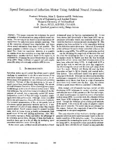
Fig. 2 -Identification of parameters R, and&,
L
f -- 0.3mH
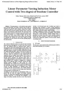
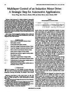
The speed reference was initially fixed in 41 radiseg First, it was decreased slowly to almost 1 radkeg and the increased to 41 radseg again. In figure 1 it can be seen that the behavior of the voltage and current varies with the change of rotor speed.
308
x
lo'
I
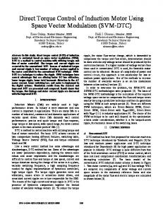
Fig. 3 - Identification of parameters MO;
51
I
I
,
,
2
1
4
,
I
!
6
7
B
9
.
:
,
5
& and L f'
10
Ttme beg]
,
I
.
Fig. 1 Measured signals. ~
The evolution of the parameters obtained by the algorithm evolves as the figures 2 and 3 shows. .O4;
\
1
!+
#
A
I
5
6
-me [sed
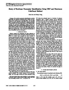
Fig. 4 - Stator fluxes estimation.
587
!5
!O
structure of the used model, EKF gains tuning and accuracy of the measure, Accelerating and decelerating references of speed produced very close estimates for the parameters. Table 2 - Parameters of the induction motor.
1
I
I
I
I
I
I
I
0.449 0
R,
0.1 14 R 0.0287 H
1.48 12 0.0209 H
0.307 m H
X
0.029 H
0.031 H
f
The parameters of the induction motor converge to = 0.4990
.,?l
=
Standards Test Procedure for Polyphase lnduction Motors and Generators, IEEE Std I 12-1996, 1997.
0.307mH
:
Atkinson D. Acamely P. Finch J . Observers for Induction Motor State and Parameter Estimation. IEEE Transactions on Industry Applications. Vol 27, no 6 NoviDic 1991.
The algorithm showed fast convergence, the parameters estimation is stabilized in 1 second as shown in the figures 2 and 3. Figures 4 and 5 show the results of the flux estimation results; however, the true states are not known.
Loron L. Zein 1. Forgez C. An extended Kalman Filter and an appropriate model for the real-time estimation of the induction motor variables and parameters. 1EEE 2000.
Table 1 - Parameters ofthe induction motor. Parameters
Initialization
Lubineau D. Commande non lineaire de moteur asynchrone avec observateur. Th&se de Doctorant. Institut National Polytechnique de Grenoble. Avril 1999.
0.499 Sl 0.1 12 R
r, = L, Ls =
+Lf
0.11452 0.0287 H
0.02 H
1
LCL
+L f
VI. REFERENCES.
0.1140
L, = 0.0287H
Lj
= L,
The estimates of the parameters converge in a short period of time ( I second). An additional feature of the method is that it provides estimations of the stator and rotor fluxes simultaneously. The method could be applied for the design of self-tuning AC drivers to optimize their performance in variable speed applications.
Fig. 5 - Rotor fluxes estimation.
R,
1
% h=L, L
L,
EKF
Manufacturer Darameters 0.441
Parameters
0.3 m H
I
0.0203 H
Slemon G . Modeling of induction Machines for Electric Drives. IEEE Transactions on Industry Applications. Vol. 25, no 6 Nov/Dic 1989. Krause P. Analysis of electric machinery. McGrawHill. 1987.
0.307 mH
0.029 H
Vilcu C. Identification et commande non lintaire adaptative de machines asynchrones. Thkse SpCciale Automatique. Institut National Polytechnique de Grenoble. Juin 1996.
V. CONCLUSION.
In this paper, an extended Kalman Fdter for identification the induction motors parameters and states was presented. The precision of this methodology is conditioned by
[8] Grewal M. Kalman Filtering: Theory and practice using Matlab. John Wiley & Sons. 2001.
588