form but it is also possible to draw some indications on the solution stability. After recalling the ...... International Journal for Numerical Methods in Engineering,. 44:1617â1652 ... FEAP: A Finite Element Analysis Program, programmer manual.
Stability of Some Finite Element Methods for Finite Elasticity Problems F. Auricchio *
*♯§
, L. Beir˜ao da Veiga
‡♯
, C. Lovadina
†♯
, and A. Reali
*§
Dipartimento di Meccanica Strutturale, Universit` a di Pavia, Italy † Dipartimento di Matematica, Universit` a di Pavia, Italy ‡ Dipartimento di Matematica, Universit` a di Milano, Italy ♯ IMATI – CNR, Pavia, Italy § ROSE School, Universit` a di Pavia, Italy
Abstract We consider the finite elasticity problem for incompressible materials, proposing a simple bidimensional problem for which we provide indications on the solution stability. Furthermore, we study the stability of the discrete solution, obtained by means of some well-known finite elements, and we present several numerical experiments in order to evaluate and compare the performance of the different discrete schemes under investigation on the considered model problem.
1 Introduction Nowadays there are several finite element interpolation schemes performing very well, in terms of both accuracy and stability, for the case of small deformation problems, also in the presence of highly constrained situations (i.e. incompressible materials). Examples with excellent performance ranges from standard mixed elements (see, for instance, Bathe, 1996, Brezzi and Fortin, 1991, Hughes, 2000, and the references therein) to enhanced strain elements (see Auricchio et al., 2005a, Braess, 1998, Pantuso and Bathe, 1995, Reddy and Simo, 1995, Simo and Rifai, 1990). However, it is also well established that the extension of such schemes to the case of finite strain problems is by no way trivial; in particular, even elements which seem to be ideal from a theoretical and a numerical perspective may fail in the large strain range, for example due to the rising of unphysical instabilities for high compression/tension states (see Armero, 2000, Auricchio et al., 2005b, Lovadina and Auricchio, 2003, Pantuso and Bathe, 1997, Wriggers and Reese, 1996, for more details). It is worth recalling that many interesting strategies have been developed in order to stabilize the methods at hand (cf., for instance, Klaas et al., 1999, Maniatty et al., 2002, Nagtegaal and Fox, 1996, Reese et al., 1999, Reese and Wriggers, 2000, Simo and Armero, 1992). However, a satisfactory analysis of finite element methods for finite strain problems is still missing. According to the cited problems, this work focuses on a simple finite-strain elastic bidimensional problem for which not only it is possible to compute the solution in closed form but it is also possible to draw some indications on the solution stability. After recalling the general finite strain elasticity framework (Section 2), we present our 2D continuum problem (Section 3). Essentially, we consider an incompressible square
1
block clamped on three sides, and subjected to a uniaxial force density, for which we vary the intensity by introducing a real parameter. For all parameter values the proposed problem admits a trivial solution, for which we study the (linearized) stability. We thus identify a stability range for the parameter choice in our continuum model problem (Section 3.1). We then present some possible finite element discretizations of the problem under investigation. In particular, in some cases, we are able to present theoretical results on the stability ranges of the discrete problems, showing the capability (or the incapability) of the considered elements to reproduce the continuum stability features (Section 4). We then perform extensive numerical simulations to investigate the whole stability range of such finite element discretizations (Section 5). We conclude by comparing the performance of the different discrete schemes with reference to the stability range expected for the continuous problem. Therefore, we can identify the elements which promise to be most reliable for the analysis of large deformation problems. We remark that most of the results presented in this work have already been discussed in Auricchio et al. (2005b).
2 The Finite Strain Incompressible Elasticity Problem In this work we adopt the so-called material description to study the finite strain elasticity problem. Accordingly, we suppose that we are given a reference configuration Ω ⊂ Rd for a d-dimensional bounded material body B. Therefore, the deformation of B can be ˆ : Ω → Rd defined by described by means of the map ϕ ˆ ˆ (X) , ϕ(X) = X+u
(2.1)
where X = (X1 , .., Xd ) denote the coordinates of a material point in the reference configˆ (X) represents the corresponding displacement vector. Following standard uration and u ˆ = F(ˆ notations, we introduce the deformation gradient F u) and the right Cauchy-Green ˆ deformation tensor C = C(ˆ u) by setting ˆ = I + ∇ˆ F u
,
ˆ =F ˆT F ˆ , C
(2.2)
where I is the second-order identity tensor and ∇ is the gradient operator with respect to the coordinates X. For a homogeneous neo-Hookean material we define (see for example Bonet and Wood, 1997, and Ciarlet, 1978) the potential energy function as Ψ(ˆ u) =
i 1 h ˆ λ ˆ2 , µ I : C − d − µ ln Jˆ + Θ(J) 2 2
(2.3)
where λ and µ are positive constants, “ : ” represents the usual inner product for secondˆ Moreover, Θ is a real function usually chosen as order tensors and Jˆ = det F. Θ(J) = ln J
or
Θ(J) = J − 1 .
(2.4)
Introducing the pressure-like variable (or simply pressure) pˆ = λΘ(Jˆ), the potential ˆ and pˆ (still denoted energy (2.3) can be equivalently written as the following function of u
2
with Ψ, with a little abuse of notations) i 1 h ˆ ˆ − 1 pˆ2 . − d − µ ln Jˆ + pˆΘ(J) (2.5) Ψ(ˆ u, pˆ) = µ I : C 2 2λ When the body B is subjected to a given load b = b(X) per unit volume in the reference configuration, the total elastic energy functional reads as follows Z Z ˆ . Π(ˆ u, pˆ) = Ψ(ˆ u, pˆ) − b·u (2.6) Ω
Ω
Therefore, following the Hellinger-Reissner variational principle, equilibrium is derived by searching for critical points of (2.6) in suitable admissible displacement and pressure ˆ and Pˆ . The corresponding Euler-Lagrange equations emanating from (2.6) lead spaces U to solve ˆ × Pˆ such that Find (ˆ u, pˆ) ∈ U Z Z Z ˆ −F ˆ −T ] : ∇v + ˆ −T : ∇v = µ [F pˆ Θ′ (Jˆ)Jˆ F b·v ∀v ∈ U (2.7) Ω Ω Ω Z � � ˆ − pˆ q = 0 Θ(J) ∀q ∈ P , λ Ω where U and P are the admissible variation spaces for the displacements and the pressures, respectively. We note that in (2.7) we used that the linearization of the deformation gradient jacobian is ˆ −T : ∇v DJ(ˆ u)[v] = J(ˆ u)F(ˆ u)−T : ∇v = Jˆ F
∀v ∈ U .
(2.8)
Without loss of generality, from now on we select Θ(J) = ln J (see (2.4)). Moreover, we focus on the case of an incompressible material, which corresponds to take the limit λ → +∞ in (2.7). Therefore, our problem becomes ˆ × Pˆ such that u, pˆ) ∈ U Find (ˆ Z Z Z −T ˆ ˆ µ F : ∇v + (ˆ p − µ)F : ∇v − b·v = 0 ∀v ∈ U (2.9) Ω Ω Ω Z q ln Jˆ = 0 ∀q ∈ P , Ω
or, in residual form,
ˆ × Pˆ such that Find (ˆ u, pˆ) ∈ U Ru ((ˆ u, pˆ), v) = 0 ∀v ∈ U Rp ((ˆ u, pˆ), q) = 0 ∀q ∈ P ,
3
(2.10)
where
Z Z Z −T ˆ ˆ R ((ˆ u , p ˆ ), v) := µ F : ∇v + (ˆ p − µ) F : ∇v − b·v u Ω Ω Ω
(2.11)
Z u, pˆ), q) := q ln Jˆ . Rp ((ˆ Ω
We now derive the linearization of problem (2.9) around a generic point (ˆ u, pˆ). Observing that ˆ −T (ˆ ˆ −T (∇u)T F ˆ −T DF u)[u] = −F ∀u ∈ U . (2.12)
we easily get the problem for the infinitesimal increment (u, p) Find (u, p) ∈ U × P such that Z Z ˆ −1 ∇u)T : F ˆ −1 ∇v µ ∇u : ∇v + (µ − pˆ)(F Ω Ω Z ˆ −T : ∇v = −Ru ((ˆ + pF u, pˆ), v) ∀v ∈ U Ω Z ˆ −T : ∇u = −Rp ((ˆ qF u, pˆ), q) ∀q ∈ P .
(2.13)
Ω
Remark 2.1. Since problem (2.13) is the linearization of problem (2.9) (or equivalently (2.10)), it can be interpreted as the generic step of a Newton-like iteration procedure for the solution of the non-linear problem (2.9). Remark 2.2. Taking (ˆ u, pˆ) = (0, 0) in (2.13), we immediately recover the classical linear incompressible elasticity problem for small deformations, i.e. Find (u, p) ∈ U × P such that Z Z Z 2µ ε (u) : ε (v) + p divv = b·v ∀v ∈ U (2.14) Ω Ω Ω Z q divu = 0 ∀q ∈ P , Ω
where ε (·) denotes the symmetric gradient operator.
3 A Model Problem for Finite Strain Incompressible elasticity In this Section we present a simple bidimensional problem which nonetheless shows some of the difficulties arising in general nonlinear elastic problems for incompressible materials.
4
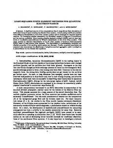
Using the usual Cartesian coordinates (X, Y ), we consider a square material body whose reference configuration is Ω = (−1, 1) × (−1, 1); we denote with Γ = [−1, 1] × {1} the upper part of its boundary, while the remaining part of ∂Ω is denoted with ΓD . The body Ω is clamped along ΓD and subjected to the volume force b = γf , where f = (0, 1)T and γ is a real parameter (cf. Fig. 1).
Figure 1. Problem 1: square incompressible block clamped on three edges and subjected to a vertical uniform body load. Therefore, the equilibrium problem leads to solve the following variational system (see (2.9)) ˆ × Pˆ such that Find (ˆ u, pˆ) ∈ U Z Z Z ˆ : ∇v + (ˆ ˆ −T : ∇v = γ µ F p − µ)F f ·v Ω Ω Ω Z q ln Jˆ = 0 ∀q ∈ P . Ω
5
∀v ∈ U
(3.1)
It is not our intention to rigorously specify the regularity needed for the space involved in the variational formulation (3.1), and we refer to Le Tallec (1982, 1994) for details on such a point. Instead, we wish to notice that system (3.1) constitutes a set of nonlinear equations for which a trivial solution can be easily found for every γ ∈ R, i.e. (ˆ u, pˆ) = (0, γr), where r = r(X, Y ) = 1 − Y . Remark 3.1. We are not claiming that, for each γ ∈ R, (ˆ u, pˆ) = (0, γr) is the only solution of the system. Whenever an incremental loading procedure is considered, the passage from γ to γ + ∆γ in (3.1) is typically solved by a Newton’s technique. Supposing that at γ convergence has been reached, the first iteration step of Newton’s method with initial guess (ˆ u, pˆ) = (0, γr) consists (recalling the linearized problem (2.13)) in solving Find (u, p) ∈ U × P such that Z Z Z Z T 2µ ε (u) : ε (v) − γ r(∇u) : ∇v + pdivv = ∆γ f ·v (3.2) Ω Ω Ω Ω Z qdivu = 0 , Ω
for every (v, q) ∈ U × P . Letting � U = v ∈ H 1 (Ω)2 : v|ΓD = 0 ;
P = L2 (Ω) ,
(3.3)
we consider system (3.2) as a model problem for our subsequent considerations. Denoting with AS the symmetric part of a generic second-order tensor A, introducing the bilinear forms Z Z aγ (F, G) =: 2µ FS : GS − γ r FT : G (3.4) Ω
and b(v, q) =:
Ω
Z
q divv ,
(3.5)
Ω
problem (3.2) can be written as Find (u, p) ∈ U × P such that Z aγ (∇u, ∇v) + b(v, p) = ∆γ f · v Ω b(u, q) = 0 ∀q ∈ P .
∀v ∈ U
(3.6)
Therefore, we are clearly facing a typical (parameter-depending) saddle-point problem. As it is well-established (cf. Brezzi and Fortin, 1991), the crucial properties for the well-posedness are, together with continuity:
6
• the inf-sup condition, i.e. the existence of a positive constant β such that inf sup
q∈P v∈U
b(v, q) ≥β ; ||v||U ||q||P
(3.7)
• the invertibility on the kernel condition, i.e. the existence of a positive constant α(γ, µ) such that inf
sup
v∈Ker B u∈Ker B
aγ (∇u, ∇v) ≥ α(γ, µ) , ||u||U ||v||U
(3.8)
where Ker B = {v ∈ U : b(v, q) = 0
∀q ∈ P } .
(3.9)
As far as the inf-sup condition is concerned, it is a classical result that it holds for the divergence operator. We therefore focus our attention on condition (3.8). In particular, we will show that the form aγ (·, ·) is coercive on Ker B whenever γ stays in a suitable range of values. We thus expect that within such choices of the parameters, for the continuous problem the trivial solution (ˆ u, pˆ) = (0, γr) is unique and stable. 3.1
The Stability Range
We now investigate on the coercivity on Ker B of aγ (·, ·). More precisely, recalling the well-known Korn’s inequality, we search for conditions on γ implying the existence of a constant c(γ, µ) > 0 such that Z Z Z ε(v)|2 − γ ε(v)|2 2µ |ε r (∇v)T : ∇v ≥ c(γ, µ) |ε ∀v ∈ Ker B . (3.10) Ω
Ω
Ω
Since div(∇v)T = 0 for every divergence-free function v (i.e. for every v ∈ Ker B), an integration by parts gives Z Z Z Z ε(v)|2 − γ ε(v)|2 + γ 2µ |ε r (∇v)T : ∇v = 2µ |ε (3.11) ∇ r · [∇v]v . Ω
Ω
Ω
Ω
Above, the boundary integral arising from integration by parts disappears because of the boundary conditions on v, and because on Γ the function r = 1 − Y vanishes. Now, a further integration by parts leads to � Z � Z Z γ r · [∇v]v = γ − H(r)v · v + (v · r)(v · n) , (3.12) ∇ ∇ Ω
Ω
Γ
where n is the outward normal vector and H(r) is the Hessian matrix of the function r. But r = 1 − Y is linear, hence H(r) = 0. On the other hand, on the boundary Γ we have ∇ r = −n, so that we deduce that Z Z 2 γ (3.13) ∇ r · [∇v]v = −γ (v · n) . Ω
Γ
7
From (3.10), (3.11) and (3.13) we conclude that our form aγ (·, ·) will be coercive on Ker B if there exists a constant c(γ, µ) > 0 such that Z Z Z 2 2 ε(v)| − γ (v · n) ≥ c(γ, µ) ε(v)|2 2µ |ε |ε ∀v ∈ Ker B . (3.14) Ω
Γ
Ω
By (3.14) we first infer that for γ ≤ 0 we can simply take c(γ, µ) = 2µ. Furthermore, setting Z (v · n)2 Γ αM = sup Z >0, (3.15) v∈Ker B ε(v)|2 |ε Ω
we see that condition (3.14) still holds whenever 2µ . αM
γ
0. Γ
∗
Choosing γ as 2µ γ ∗ := Z
Z
Ω
Γ
it follows that 2µ
Z
Ω
ε(w)|2 |ε
,
(3.17)
(w · n)2 ≤ 0
(3.18)
(w · n)2
ε(w)|2 − γ |ε
Z
Γ
for all γ ≥ γ ∗ . Therefore, coercivity on the kernel surely fails for sufficiently large values of γ. A consequence of Proposition 3.2 is that the linearized continuous problem (3.2) is well-posed and positive-definite on the relevant kernel Ker B if γ∈
�
− ∞,
2µ � ⊇ (−∞, 3µ) . αM
8
(3.19)
4 Discrete Stability Range: Some Theoretical Results For a finite analysis of the problem presented in Section 3, one should obviously focus on schemes which are reliable at least in the infinitesimal strain regime, otherwise even the first iteration step will fail. This can be accomplished by considering finite element methods satisfying the discrete inf-sup condition, as the ones studied in this Section. As proved in Subsection 3.1, the continuous linearized problems (3.2) are surely stable, in the sense that both the inf-sup and the coercivity on the kernel conditions hold true, whenever the parameter γ satisfies γ ∈ (−∞, 3µ) .
(4.1)
On the other hand, the linearized problems (3.2) become unstable for suitable large values of γ (cf. Remark 3.3). We point out that this lack of stability is only addressed to a failure of the coercivity on the kernel condition. Indeed, for the proposed problem the inf-sup condition is independent of γ, and therefore it is the same one required for the small deformation framework. Since a reliable numerical approximation should be able to correctly reproduce the stability properties of the continuous problem, the discussion above highlights the importance of studying whether or not a given finite element method satisfies a discrete coercivity on the kernel condition, at least for γ in the range shown by (4.1). With this respect, we consider the MINI element (cf. Arnold et al., 1984) and the QME element (cf. Pantuso and Bathe, 1995), rigorously proving that their stability range are somehow quite different from the continuous problem one. However, we point out that our theoretical analysis is far from being complete, although in accordance with the numerical tests presented in Section 5. 4.1
The MINI Element
We now consider the discretized counterpart of problem (3.2), using the MINI element (cf. Arnold et al., 1984). Let Th be a triangular mesh of Ω, h being the meshsize. For the discretization of the displacement field, we take � Uh = vh ∈ U : vh|T ∈ P1 (T )2 + B(T )2
∀T ∈ Th
,
(4.2)
where P1 (T ) is the space of linear functions on T , and B(T ) is the linear space generated by bT , the standard cubic bubble function on T . For the pressure discretization, we take � Ph = qh ∈ H 1 (Ω) : qh|T ∈ P1 (T )
∀T ∈ Th
Therefore, the discretization of problem (3.2) reads as follows.
9
.
(4.3)
Find (uh ; ph ) ∈ Uh × Ph such that: Z Z 2µ ε (uh ) : ε (vh ) − γ r (∇uh )T : ∇vh Ω Ω Z Z + ph divvh = ∆γ f · vh Ω Ω Z qh divuh = 0 Ω
Introducing the discrete kernel as � Z Kh = vh ∈ Uh : qh divuh = 0
∀vh ∈ Uh ∀qh ∈ Ph .
∀qh ∈ Ph
Ω
(4.4)
�
,
(4.5)
we are interested in analyzing for which γ there exists a constant cM (γ, µ) > 0 such that Z aγ (∇vh , ∇vh ) ≥ cM (γ, µ) | ε (vh ) |2 ∀vh ∈ Kh , (4.6) Ω
where aγ (∇vh , ∇vh ) := 2µ
Z
Ω
ε (vh ) : ε (vh ) − γ
Z
Ω
r (∇vh )T : ∇vh .
(4.7)
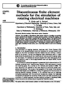
We consider the meshes used for the numerical tests presented in Section 5. Therefore Th is built by squares of side 2h, each divided into eight triangles according with the pattern shown in Fig. 2. We have the following results. Proposition 4.1. For problem (4.4), the discrete coercivity on the kernel condition (4.6) does not hold, whenever γ > 3µ/2. Proposition 4.2. For problem (4.4), the discrete coercivity on the kernel condition (4.6) is satisfied, independently of the meshsize, whenever γ < µ. For the proofs of these Propositions see Auricchio et al. (2005b) or Appendix Sections A.2 and A.3. 4.2
The QME Element
We now consider the discretized counterpart of problem (3.2), using the QME quadrilateral method proposed by Pantuso and Bathe (1995), based on the Enhanced Strain Technique (cf. Simo and Rifai, 1990, for instance). This scheme optimally performs in small deformation regimes, as theoretically proved by Lovadina (1997). For our analysis we consider uniform meshes Th formed by equal square elements K with side length h, as the ones used in the numerical tests of Section 5. The Pantuso-Bathe element is described by the following choice of spaces. For the discretization of the displacement field, we take � Uh = vh ∈ U : vh|K ∈ Q1 (K)2 ∀K ∈ Th , (4.8)
10
Figure 2. Triangular mesh for the MINI element.
where Q1 (K) is the standard space of bilinear functions. For the pressure discretization, we take � Ph = qh ∈ H 1 (Ω) : qh|K ∈ Q1 (K) ∀K ∈ Th . (4.9) Furthermore, the Enhanced Strain space is described by � Sh = Eh ∈ (L2 (Ω))4 : Eh|K ∈ E6 (K)
∀K ∈ Th
.
(4.10)
Above, E6 (K) is the space of tensor-valued functions defined on K, spanned by the following shape functions �
α1 ξ + α2 ξη α4 η
; α3 ξ ; α5 η + α6 ξη
�
with αi ∈ R ,
where (ξ, η) denotes the standard local coordinates on K. Therefore, the discretization of problem (3.2) reads as follows.
11
(4.11)
Find (uh , Hh ; ph ) ∈ (Uh × Sh ) × Ph such that: Z Z 2µ (∇uh + Hh )S : (∇vh + Eh )S − γ r (∇uh + Hh )T : (∇vh + Eh ) Ω Ω Z Z + ph (divvh + trEh ) = ∆γ f · vh ∀(vh , Eh ) ∈ Uh × Sh Ω Ω Z ∀qh ∈ Ph . qh (divuh + trHh ) = 0
(4.12)
Ω
Above and in the sequel, we denote with “tr ” the trace operator acting on tensors. Introducing the discrete kernel as � � Z Kh = (vh , Eh ) ∈ Uh × Sh : qh (divvh + trEh ) = 0 ∀qh ∈ Ph , (4.13) Ω
we are interested in analyzing for which γ there exists a constant cE (γ, µ) such that (cf. (3.4)) Z � ε(vh )|2 + |Eh |2 (4.14) aγ (∇vh + Eh , ∇vh + Eh ) ≥ cE (γ, µ) |ε Ω
for every (vh , Eh ) ∈ Kh . We have the following result (see Auricchio et al., 2005b).
Proposition 4.3. For the choice (4.8)–(4.11), the discrete coercivity on the kernel condition does not hold, whenever γ > µ. The proof for this Proposition is reported in the Appendix Section A.4.
5 Numerical Tests We now study the computational performance of some specific finite element interpolations on the model problem presented in previous Sections. In particular, we wish to numerically detect the stability range of the elements under investigation, and, when it is possible, to compare such numerical results with the theoretical ones previously obtained for some discrete problems as well as for the continuous one. The interpolation schemes we deal with in this Section are • MINI – Triangular element with piecewise linear continuous approximation for both displacements and pressure, with the displacements enriched by a cubic bubble as proposed by Arnold et al. (1984); • QME – Quadrilateral element with piecewise bilinear continuous approximation for both displacements and pressure, enriched by the Enhanced Strains as proposed by Pantuso and Bathe (1995); • Q2P1 – Quadrilateral element with piecewise biquadratic continuous approximation for displacements and piecewise linear approximation for pressure;
12
• QE1 – Quadrilateral element with piecewise bilinear continuous approximation for displacements, enriched by the Enhanced Strains as proposed by Simo and Armero (1992); • QE2 – Quadrilateral element with piecewise bilinear continuous approximation for displacements, enriched by the Enhanced Strains as proposed by Glaser and Armero (1997). All the schemes have been implemented within the research-oriented finite element environment FEAP (see Taylor, 2001). The model problem on which we perform our numerical studies is the square incompressible block clamped on three edges and subjected to a vertical uniform body load depicted in Fig. 1 (cf. Section 3). We remark that for non-mixed formulations only nearly incompressible conditions can be considered. Assuming to express respectively forces and lengths in KN and m, we set µ = 40 and we select a body load γ(0, 1)T , where γ plays the role of load multiplier; moreover for non-mixed formulations we set λ = 4 · 105 in order to make the problem nearly incompressible. Here and in the following, we find convenient to express the numerical results in terms of the nondimensional quantity γ˜ defined as γ˜ = γL/µ with L some problem characteristic length, set equal to 1 for simplicity and consistently with the model problem. For a given interpolation scheme and for a given mesh, in order to numerically detect the element stability range we progressively increase the load multiplier γ, adopting an iterative Newton’s scheme to obtain the solution corresponding to the single load value from the solution corresponding to the previous load value. In particular, we increase the load multiplier until some form of numerical instability appears (e.g., appearance of negative eigenvalues, divergence of the solution, etc.); we indicate the load multiplier corresponding to the first appearance of numerical instabilities as γcr and the corresponding nondimensional multiplier as γ˜cr = γcr L/µ. To investigate very large load multiplier intervals, we adopt different increments ∆γ depending on the load level (cf. Table 1). Accordingly, we do a series of sequential analyses. In the first one, we increase the load multiplier γ from 0 to a maximum value γ = 102 using load increments ∆γ = 10−1 . If no instability is detected, we repeat the analysis increasing now the load multiplier γ from 0 to γ = 103 using load increments ∆γ = 1, and we keep on going until a numerical instability appears. Table 1. Load increments ∆γ (depending on the load level γ) for the Newton’s scheme. ∆γ ∆γ ∆γ ∆γ ∆γ
= 10−1 =1 = 10 = 102 = 103
up up up up up
to to to to to
γ γ γ γ γ
= 102 = 103 = 104 = 105 = 106
Clearly, the analyses are performed starting from γ˜ = 0 for both positive and negative loading conditions, i.e. for γ˜ < 0 and γ˜ > 0. If we do not detect numerical instabilities
13
even for extremely large values of the load multiplier, we set γ˜cr = ∞. Finally, to make immediately clear the comparisons among different elements and meshes, we identify any given mesh with the label “n × n”, being n the number of displacement nodes per side of the mesh. Table 2 reports the stability limits for the different considered interpolation schemes when applied to our model problem. From such results the following observations arise. • The theoretical predictions for the MINI interpolation scheme are that the discrete problem is stable for −∞ < γ˜ < 1 and unstable for γ˜ > 3/2 (cf. Propositions 4.1 and 4.2). The results presented in Table 2 show that the corresponding numerical problem is stable for −∞ < γ˜ < 1, unstable for γ˜ > 3/2. In particular, the stability upper limit approaches monotonically 1 from above during the mesh refinement (i.e. for h → 0). Accordingly, for the MINI interpolation scheme the numerical results confirm the theoretical predictions. • The theoretical predictions for the QME interpolation scheme are that for sufficiently small h the discrete problem is unstable for γ˜ > 1 (cf. Proposition 4.3). The numerical experiments seem to indicate that for sufficiently small h the corresponding numerical problem is stable for −∞ < γ˜ < 1 and unstable for γ˜ > 1. In particular, the stability lower limit is decreasing almost linearly with h, approaching −∞ for h → 0, while the stability upper limit is about 1 but it does not seem to have a smooth convergence. Accordingly, also for the QME interpolation scheme the numerical results confirm the theoretical predictions. • We do not have theoretical prediction for the Q2P1 discrete problem, except the trivial one telling that the problem is stable in the range −1 < γ˜ < 1 (cf. the beginning of Proposition 4.2 proof). However, the results relative to the Q2P1 interpolation scheme indicate that the numerical problem is stable for −∞ < γ˜ < 1. • Also for the enhanced discrete problems (elements QE1 and QE2), only the trivial theoretical prediction is available (stability for −1 < γ˜ < 1). For element QE1, it seems that the trivial range is the one recovered from the numerical results, as h becomes small; element QE2 has a similar behaviour for positive values of γ˜ , but the stability range in compression appears to be much larger than with QE1, even if it seems to get smaller as h decreases (but a smooth convergence to a stable value cannot be observed). We remark that in Table 2, where the numerical results referred to elements QE1 and QE2 are reported, some values are followed by one or two asterisks. Their meaning is that no instabilities are detected when using in the analysis a load level of γ = 102 , but anyway an instability appears for γ < 102 when an higher load level is considered (along with its corresponding load increment, cf. Table 1). In particular, one asterisk (*) indicates that a load level of γ = 103 is used, while two asterisks (**) indicate that a load level of γ = 104 is used. As a conclusion to our study, we recall that the continuous problem is stable at least for −∞ < γ˜ < 3 (see (3.19)), and that for a sufficiently large value of γ˜ the problem gets unstable (see Remark 3.3). Therefore, we may state that all the interpolation schemes fail in properly detecting the stability range of the continuous problem. However we have to notice that all the considered mixed formulations show a much better behaviour in compression with respect to the (non-mixed) enhanced ones. Finally, the MINI and
14
Table 2. Stability limits for the studied numerical schemes on the model problem of − + Fig. 1 in the cases of compression (˜ γcr ) and tension (˜ γcr ). The asterisks mean that (nondimensional) load levels of γ˜ = ±25 (*) or γ˜ = ±250 (**) are used instead of γ˜ = ±2.5 mesh 5×5 9×9 17 × 17 33 × 33 65 × 65
MINI − + γ˜cr γ˜cr −∞ 1.28 −∞ 1.22 −∞ 1.19 −∞ 1.18 −∞ 1.17
QME − + γ˜cr γ˜cr -52.8 1.21 -150 1.07 -335 0.998 -723 0.978 -1480 0.980
Q2P1 − + γ˜cr γ˜cr −∞ 1.46 −∞ 1.16 −∞ 1.07 −∞ 1.03 −∞ 1.01
QE1 − + γ˜cr γ˜cr -2.38 2.38 -1.75∗∗ 1.60∗∗ -1.50∗∗ 6.80 -1.87 1.82 -1.65 1.10
QE2 − + γ˜cr γ˜cr -1060 4.53 -723 1.88∗ -588 1.43∗ -460 1.25∗ -645 1.13
the Q2P1 interpolation schemes seem to be the most effective. Indeed, they are the elements able to reproduce more closely (but still in a deficient form) the continuous problem behavior, as shown in Table 3, where we qualitatively evaluate the performance of the studied numerical schemes. The meaning of the symbols used in the Table is the following: XX : optimal performance; X : good performance; ♠ : poor performance; ♠♠ : very poor performance. Table 3. Qualitative performance evaluation of the studied numerical schemes. MINI γ˜ < 0 γ˜ > 0 XX ♠
QME γ˜ < 0 γ˜ > 0 X ♠
Q2P1 γ˜ < 0 γ˜ > 0 XX ♠
QE1 γ˜ < 0 γ˜ > 0 ♠♠ ♠
QE2 γ˜ < 0 γ˜ > 0 ♠ ♠
6 Conclusions We have proposed a simple 2D finite-strain problem depending on a loading parameter, for which a trivial solution can be easily computed. We have proved the stability of such a solution whenever the loading parameter stays in a suitable range of values. Furthermore, we have considered and analyzed the problem discretization by means of some finite element schemes, which are known to efficiently behave in the framework of small deformation problems. In particular, we have proved that the elements fail to properly detect the problem stability range. We have also presented several numerical
15
experiments, in accordance with the theoretical predictions, showing which elements behave better on the considered model problem. However, we notice that a completely satisfactory analysis of finite element schemes for large deformation problems is still missing. Therefore, we think it could be valuable to propose other benchmarks in the spirit of the present work.
Bibliography F. Armero. On the locking and stability of finite elements in finite deformation plane strain problems. Computers & Structures, 75:261–290, 2000. D. N. Arnold, F. Brezzi, and M. Fortin. A stable finite element for the stokes equation. Calcolo, 21:337–344, 1984. F. Auricchio, L. Beir˜ao da Veiga, C. Lovadina, and A. Reali. An analysis of some mixedenhanced finite element for plane linear elasticity. Computer Methods in Applied Mechanics and Engineering, 194:2947–2968, 2005a. F. Auricchio, L. Beir˜ao da Veiga, C. Lovadina, and A. Reali. A stability study of some mixed finite elements for large deformation elasticity problems. Computer Methods in Applied Mechanics and Engineering, 194:1075–1092, 2005b. K. J. Bathe. Finite Element Procedures. Prentice Hall, Englewood Cliffs, NJ, 1996. J. Bonet and R. D. Wood. Nonlinear Continuum Mechanics for Finite Element Analysis. Cambridge University Press, 1997. D. Braess. Enhanced assumed strain elements and locking in membrane problems. Computer Methods in Applied Mechanics and Engineering, 165:155–174, 1998. F. Brezzi and M. Fortin. Mixed and Hybrid Finite Element Methods. Springer-Verlag, New York, 1991. P. G. Ciarlet. The Finite Element Methods for Elliptic Problems. North-Holland, Amsterdam, 1978. S. Glaser and F. Armero. On the formulation of enhanced strain finite elements in finite deformations. Engineering Computations, 14:759–791, 1997. T. J. R. Hughes. The Finite Element Method: Linear Static and Dynamic Finite Element Analysis. Dover Publications, Mineola, New York, 2000. O. Klaas, A. M. Maniatty, and M. S. Shephard. A stabilized mixed petrov-galerkin finite element method for finite elasticity. formulation for linear displacement and pressure interpolation. Computer Methods in Applied Mechanics and Engineering, 180:65–79, 1999. P. Le Tallec. Existence and approximation results for nonlinear mixed problems: application to incompressible finite elasticity. Numerische Mathematik, 38:365–382, 1982. P. Le Tallec. Numerical methods for nonlinear three-dimensional elasticity. In P. G. Ciarlet and J. L. Lions, editors, Handbook of Numerical Analysis, volume III, pages 465–622. Elsevier Science, North Holland, 1994. C. Lovadina. Analysis of strain-pressure finite element methods for the stokes problem. Numerical Methods for PDE’s, 13:717–730, 1997. C. Lovadina and F. Auricchio. On the enhanced strain technique for elasticity problems. Computers & Structures, 81:777–787, 2003.
16
A. M. Maniatty, Y. Liu, O. Klaas, and M. S. Shephard. Higher order stabilized finite element method for hyperelastic finite deformation. Computer Methods in Applied Mechanics and Engineering, 191:1491–1503, 2002. J. C. Nagtegaal and D. D. Fox. Using assumed enhanced strain elements for large compressive deformation. International Journal of Solids and Structures, 33:3151– 3159, 1996. D. Pantuso and K. J. Bathe. A four-node quadrilateral mixed-interpolated element for solids and fluids. Mathematical Models & Methods in Applied Sciences, 5:1113–1128, 1995. D. Pantuso and K. J. Bathe. On the stability of mixed finite elements in large strain analysis of incompressible solids. Finite Elements in Analysis and Design, 28:83–104, 1997. B. D. Reddy and J. C. Simo. Stability and convergence of a class of enhanced strain methods. SIAM Journal on Numerical Analysis, 32:705–1728, 1995. S. Reese, M. K¨ ussner, and B. D. Reddy. A new stabilization technique for finite elements in non-linear elasticity. International Journal for Numerical Methods in Engineering, 44:1617–1652, 1999. S. Reese and P. Wriggers. A stabilization technique to avoid hourglassing in finite elasticity. International Journal for Numerical Methods in Engineering, 48:79–109, 2000. J. C. Simo and F. Armero. Geometrically nonlinear enhanced strain mixed methods and the method of incompatible modes. International Journal for Numerical Methods in Engineering, 33:1413–1449, 1992. J. C. Simo and M. S. Rifai. A class of mixed assumed strain methods and the method of incompatible modes. International Journal for Numerical Methods in Engineering, 29:1595–1638, 1990. R. L. Taylor. FEAP: A Finite Element Analysis Program, programmer manual. http://www.ce.berkeley.edu/∼rlt/feap/, 2001. P. Wriggers and S. Reese. A note on enhanced strain methods for large deformations. Computer Methods in Applied Mechanics and Engineering, 135:201–209, 1996.
17
A Mathematical Proofs A.1
Proof for Proposition 3.2
¯ and observe that on Γ we have v · n = v2 . Take v = (v1 , v2 ) ∈ (Ker B) ∩ C 1 (Ω) Therefore Z Z 2 (v · n) = |v2 |2 . (A.1) Γ
Γ
Since for every X ∈ [−1, 1] it holds v2 (X, −1) = 0, we get v2 (X, 1) =
Z
1
v2,Y (X, Y )dY .
−1
Hence, the Cauchy-Schwarz inequality gives Z Z |v2 |2 ≤ 2 |v2,Y |2 . Γ
(A.2)
Ω
Using divv = 0, we obtain Z Z Z Z Z 2 2 2 2 |v2 | ≤ |v1,X | + |v2,Y | ≤ | ε11 (v) | + | ε22 (v) |2 Γ
Ω
Ω
Ω
(A.3)
Ω
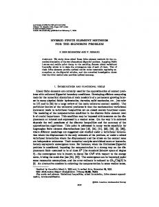
¯ for all v ∈ (Ker B) ∩ C 1 (Ω). Before proceeding, we need to introduce some notation. For every point P = (X, 1) 1 with X ∈ [−1, 1], we define the oriented rectilinear path from point PX to point P (see Fig. 3), parameterized by √ √ √ γ 1X (s) = (−1 + s/ 2, −X + s/ 2) s ∈ [0, 2(X + 1)] , (A.4) and with unit tangent vector
√ √ τ 1 = (1/ 2, 1/ 2) .
(A.5)
2 Similarly, for every X ∈ [−1, 1], we define the oriented rectilinear path from point PX to point P (see Fig. 3), parameterized by √ √ √ γ 2X (s) = (1 − s/ 2, X + s/ 2) s ∈ [0, 2(1 − X)] , (A.6)
and with unit tangent vector √ √ τ 2 = (−1/ 2, 1/ 2) .
(A.7)
1 Moreover, we introduce the union path γ X = γ 1X ∪ {−γ 2X } going from point PX to 2 point PX . For all X ∈ [−1, 1], it clearly holds
1 1 v2 (X, 1) = √ v(X, 1) · τ 1 + √ v(X, 1) · τ 2 . 2 2
18
(A.8)
y
P=(X,1)
γX
2
γX1
2
PX
X 1
PX
Figure 3. Oriented paths γ 1X and γ 2X on Ω. Observing that v vanishes on {−1} × [−1, 1] and integrating along γ 1X , the first term in the right-hand side of (A.8) can be written as v(X, 1) · τ 1 =
Z
√
2(X+1)
1 ∇(v · τ 1 )(γ X (s)) · τ 1 ds ,
0
(A.9)
which, after some simple algebra, gives v(X, 1) · τ 1 =
Z
√
2(X+1)
� ε v(γ 1X (s)) τ 1 · τ 1 ds .
0
(A.10)
Recalling that divv = 0, it is easy to see that in Ω we have ε (v)τ 1 · τ 1 = ε12 (v) .
(A.11)
Using (A.11) and (A.10), we obtain v(X, 1) · τ 1 =
Z
√ 2(X+1)
ε12 (γ 1X (s)) ds ,
0
or, in more compact form, v(X, 1) · τ 1 =
19
Z
ε12 (v) . γ 1X
(A.12)
(A.13)
Treating similarly the second term in the right-hand side of (A.8), but using the path γ 2X , it can be shown that Z v(X, 1) · τ 2 = − ε12 (v) . (A.14) γ 2X Recalling (A.8), from (A.13) (A.14) we get Z Z Z � 1 1 v2 (X, 1) = √ ε12 (v) − ε12 (v) = √ ε12 (v) , 2 γ 1X 2 γX γ 2X so that we obtain Z Z | v2 |2 = Γ
1
−1
(A.15)
Z 2 ε12 (v) dX . (A.16) −1 γ X √ |= 2 2 for all X ∈ [−1, 1], the Cauchy-
1 | v2 (X, 1) | dX = 2 2
Z
1
From (A.16) and observing that | γ 1X | + | γ 2X Schwarz inequality yields Z √ Z 1 Z � 2 | v2 | ≤ 2 | ε12 (v) |2 dX . Γ −1 γX
(A.17)
Setting � Ω1 = (X, Y ) ∈ Ω : Y ≥ X
� Ω2 = (X, Y ) ∈ Ω : Y ≥ −X ,
we easily get, using a simple change of variables, Z 1Z √ Z √ Z 2 2 | ε12 (v) | = 2 | ε12 (v) | ≤ 2 | ε12 (v) |2 , 1 −1 γ X Ω1 Ω and Z
1
Z
√ Z | ε12 (v) | = 2 2
(A.18)
(A.19)
√ Z | ε12 (v) | ≤ 2 | ε12 (v) |2 . 2
(A.20) γ 2X Ω2 Ω From (A.17), splitting the integral on γ X into the contributions on γ 1X and γ 2X , using bounds (A.19)-(A.20) we obtain Z Z | v2 |2 ≤ 4 | ε12 (v) |2 . (A.21) −1
Γ
Ω
Recalling (A.1), from (A.3) and (A.21) it follows Z Z 2 2 |v · n| ≤ | ε (v) |2 3 Ω Γ ¯ for all v ∈ (Ker B) ∩ C 1 (Ω). By density the same estimate holds in Ker B, so that Z (v · n)2 2 Γ αM = sup Z ≤ , 3 v∈Ker B 2 ε(v)| |ε Ω
which concludes the proof.
20
(A.22)
(A.23)
A.2
Proof for Proposition 4.1
Take any two adjacent triangles T1 and T2 , both with a side contained in [−1, 1]×{−1} (see Fig. 2). Consider the function wh = (w1 , w2 ) ∈ Uh defined as on T1 bT1 w1 = 0 ; w2 = −bT2 on T2 (A.24) 0 otherwise . It is easy to see that Z Z qh divwh = Ω
T1 ∪T2
qh divwh = −
Z
T1 ∪T2
∇qh · wh = 0
∀qh ∈ Ph ,
so that wh ∈ Kh . From (4.7) and (A.24), we get � � Z Z 1 aγ (wh , wh ) = 2µ (w2,Y )2 + (w2,X )2 − γ (1 − Y ) (w2,Y )2 . 2 T1 ∪T2 T1 ∪T2 Using that for our particular mesh it holds Z Z (bT,Y )2 = (bT,X )2 T
T
∀T ∈ Th ,
(A.25)
(A.26)
(A.27)
and noting that on T1 ∪ T2 we obviously have Y < h − 1, from (A.24) and (A.26) it follows Z � aγ (w, w) ≤ 3µ − (2 − h)γ (w2,Y )2 . (A.28) T1 ∪T2
Therefore the form aγ (·, ·) fails to be coercive on Kh whenever γ and h are such that 3µ − (2 − h)γ ≤ 0 .
(A.29)
It follows that, for γ > 3µ/2, the coercivity on the kernel breaks down, provided h is sufficiently small. A.3
Proof for Proposition 4.2
It is easy to check that, for −µ < γ < µ and −1 < Y < 1, there exists a constant c > 0 such that 2µAS : AS − γrAT : A ≥ c | AS |2 (A.30) for every second order tensors A. From the pointwise positivity property (A.30) it easily follows that, for −µ < γ < µ, the bilinear form (see (4.7)) Z Z aγ (∇u, ∇v) = 2µ ε (u) : ε (v) − γ r (∇u)T : ∇v (A.31) Ω
Ω
is coercive on the whole space U (and therefore in particular for Kh ⊆ Uh ⊆ U ).
21
We will now prove that for vh ∈ Kh it holds Z r (∇vh )T : ∇vh ≥ 0 .
(A.32)
Ω
Once estimate (A.32) has been established, also for γ < 0 the coercivity property (4.6) immediately follows, and the proof is complete. We first observe that (∇vh )T = (divvh ) I − cof[∇vh ] .
(A.33)
Using (A.33) and integrating by parts we have Z Z R 2 T r (∇v ) : ∇v = r(divv ) − rcof[∇vh ] : ∇vh h h h Ω Ω
=
Z
Ω
r(divvh )2 +
Ω
Z
Ω
div(rcof[∇vh ]) · vh ,
(A.34)
where all the boundary integrals vanish because the function rvh vanishes on the whole boundary ∂Ω. Due to Piola’s identity and using (A.33) we have Z R div(rcof[∇v ]) · v = cof[∇vh ]∇r · vh h h Ω Ω
=−
Z
Ω
(∇vh )T ∇r · vh +
Z
Ω
(divvh )∇r · vh .
(A.35)
Recalling that on Γ we have ∇r = −n, simple algebra and an integration by parts give Z R T ∇r · [∇vh ]vh − Ω (∇vh ) ∇r · vh = − Ω
= =
Z Z
Ω
Ω
(divvh )∇r · vh −
Z
(vh · n)(vh · ∇r)
(divvh )∇r · vh +
Z
| vh · n |2 .
Γ
Γ
Using (A.34), (A.35) and (A.36) it follows Z Z Z Z T 2 r (∇vh ) : ∇vh = r(divvh ) + 2 (divvh )(∇r · vh ) + | vh · n |2 . Ω
Ω
Ω
(A.36)
(A.37)
Γ
We now split each component of vh in its linear and bubble parts, i.e. vh = vhL + vhB = (v1L + v1B , v2L + v2B ) .
22
(A.38)
Accordingly, noting also that ∇r · vh = −(v2L + v2B ) ,
(A.39)
equation (A.37) can be written as Z R �2 T r (∇vh ) : ∇vh = r div(vhL + vhB ) Ω Ω
−2
Z
Ω
� div(vhL + vhB ) (v2L + v2B ) +
Z
Γ
| (vhL + vhB ) · n |2
= A1 + A2 + A3 .
(A.40)
We now estimate the three terms above. We obviously have Z Z � L B 2 r(divvhL )(divvhB ) . A1 := r div(vh + vh ) ≥ 2
(A.41)
Ω
Ω
Integrating by parts and using that ∇r · vhB = −v2B , from (A.41) we obtain Z Z A1 ≥ −2 (divvhL )∇r · vhB = 2 (divvhL )v2B .
(A.42)
Ω
Ω
Recalling that vh = vhL + vhB ∈ Kh and observing that v2L is a continuous piecewise linear function, it follows that Z Z � � A2 := −2 div(vhL + vhB ) (v2L + v2B ) = −2 div(vhL + vhB ) v2B . (A.43) Ω
Since it holds
Ω
Z
Ω
(divvhB )v2B = 0 ,
(A.44)
from (A.43) we get A2 = −2
Z
Ω
(divvhL )v2B .
(A.45)
Furthermore, for A3 we obviously have Z A3 := | (vhL + vhB ) · n |2 ≥ 0 . Γ
Collecting (A.42),(A.45) and (A.46), we finally get (cf. (A.40)) Z Z Z r (∇vh )T : ∇vh ≥ 2 (divvhL )v2B − 2 (divvhL )v2B = 0 . Ω
Ω
Ω
The Proposition is proved.
23
(A.46)
A.4
Proof for Proposition 4.3
Let us define the set F (γ) ⊂ Ω by � F (γ) = (X, Y ) ∈ Ω : 2µ − γ r(X, Y ) ≤ 0 .
(A.47)
Recalling that r(X, Y ) = 1 − Y , the set F (γ) has positive area for γ > µ. It follows ˜ ∈ Th completely contained in F (γ). Now that, for sufficiently small h, there exists K ˜ Moreover, in take (vh , Eh ) ∈ Uh × Sh by choosing vh = 0 and Eh vanishing outside K. ˜ K choose (cf. (4.11)) � � αξη ; 0 Eh|K˜ = with α 6= 0 . (A.48) 0 ; −αξη Notice that trEh = 0; hence (0, 0) 6= (0, Eh ) ∈ Kh (cf. (4.13)). On the other hand, a direct computation shows that Z aγ (Eh , Eh ) = (2µ − γ r)|Eh |2 . (A.49) ˜ K
˜ ⊆ F (γ), we have (2µ − γ r) ≤ 0, so that (A.49) implies Since K aγ (Eh , Eh ) ≤ 0 . h.
(A.50)
As a consequence the form aγ (·, ·) cannot be coercive on Kh for γ > µ, uniformly in
24