International Journal of Signal Processing, Image Processing and Pattern Recognition Vol.8, No.7 (2015), pp.213-222 http://dx.doi.org/10.14257/ijsip.2015.8.7.20
Study on Signal Processing Technology based on the Reflective Intensity Modulated Fiber Optic Sensor 1
Junjie Yang, 2Zhihe Fu, 2Yibiao Fan, 1*Wenxiang Chen, 1Zhiping Xie and 1Wei Wu 1
Department of Mechanical and Electrical Engineering, Xiamen University, Xiamen, Fujian 361005, China 2 Department of Mechanical and Electrical Engineering, Longyan College, Longyan, Fujian 364012, China
[email protected] Abstract
Sensor technology is one of the most representative of the emerging technology. At present, the sensor has been widely used in national defence, industry, agricultural production, environmental protection, biological science, measurement, transportation, each field of automatic control and household appliances, etc.. Optical fiber sensing technology is accompanied by the development of optical communication technology gradually formed, compared all kinds of optical fiber sensor and the traditional sensor has a series of unique advantages, such as high sensitivity, anti-electromagnetic interference, corrosion resistance, electrical insulation, explosion-proof, light path with the flexible, convenient for connecting with a computer, the structure is simple, small volume, light weight, low power. In this paper, the intensity modulation type reflective optical fiber displacement sensor, studied the basic principle, in fact, is the displacement measurement in particular, on the assumption that the condition of uniform distribution, the emergent light field is analyzed in detail, the expression intensity modulation function under various conditions were obtained. Keywords: Algorithm; Fiber optic displacement sensor; Band-pass filter
Weak signal processing;
1. Introduction In recent years, optical fiber sensors have been widely used in various industries [1]. In particular, with the rapid development of communication industry, the application of optical fiber is also increased. The research of optical fiber sensor has been more in-depth. Optical fiber sensor has the advantages of some other traditional electromagnetic sensor can match, especially suitable for some worse condition, therefore, it is of great significance to study the optical fiber sensor. With the rapid development of communication industry, optical fiber sensors have been widely used in all aspects of the industry [2]. Compared with the traditional electromagnetic sensor, optical fiber sensor has the very big difference in the detection principle [3-5]. Detection is the basis of industry, displacement detection is one of the most common means of detection in mechanical industry, and to realize the displacement detection using optical fiber sensor has great potential for development [6]. For example [7], optical fiber displacement sensor can be used in many kinds of occasions detection by detecting the surface morphology, surface morphology to finally realize the reconstruction of 3D topography, which compared with traditional electromagnetism sensor has great advantages, detection accuracy is guaranteed, but also in the abominable environment continue to use without failure [8].
ISSN: 2005-4254 IJSIP Copyright ⓒ 2015 SERSC
International Journal of Signal Processing, Image Processing and Pattern Recognition Vol.8, No.7 (2015)
The main purpose of this paper is to study the working principle of reflective optical fiber displacement sensor based on intensity modulation, concrete implementation scheme is proposed for detection of weak photoelectric signal, according to the detection scheme, a reasonable choice of devices, design the corresponding optical fiber displacement sensor signal processing circuit, finally completes the circuit debugging, which can accurately detect the light signal passing through and the modulation filter noise, that the measured displacement [9, 10]. At present in the industrial field in common are: mechanical displacement measuring instrument, often with a mechanical transmission mechanism (lever, gear, rack etc.) measurement of the displacement magnification and, some with optical reading device corresponding; displacement of the sensor structure is changed, the displacement is converted into electricity, such as a potentiometer type sensor (displacement of the sliding contact mobile), capacitance sensor (variable distance, variable area type), eddy current sensor, Holzer sensor can realize the displacement measurement; use effect of some functional materials, such as piezoelectric sensor, metal strain plate and semiconductor strain resistance, the displacement transformation into small pressure to the piezoelectric sensor the crystal surface charge sheet or the strain resistance changes to achieve the displacement measurement; magnetoelectric: magnetic grid (linear disc) and inductosyn (linear, circular) [11]. With the development of optical detection element and the precision manufacturing process improvement and electronic components, with the development of computer automatic control technology and the upgrading of the industry, combined with the method of using photoelectric is an effective way to solve the above problems, such as grating, encoder, triangulation, spot scattering method, its measurement precision is high, the reaction speed is fast, easy to realize digital measurement, but the back-end circuit and digital processing device is complex, expensive. In recent years, high precision, high speed object displacement measurement has attracted more and more attention, especially the measurement of small displacement of the narrow space of the doing a lot of research and discussion. Thus, displacement measurement by optical method more and more, especially the displacement measurement method using optical fiber sensing technology has the unique advantage of the much attention. Displacement detection system is often affect the control performance of the system, although the displacement detection in different conditions detection requirements focus is different, but the basic requirement of similar, all want to fast, accurate and reliable and economical realization of displacement measurement.
2. Related Theory 2.1 The Basic Components of Optical Fiber Sensor Optical fiber sensor, as a kind of detection device, in the external environment of various physical, chemical content, biomass effect, will make some specific optical properties of light transmission in fiber to change, a process known as modulation also, corresponding to the modulator part of optical fiber sensor, detecting part through changes optical properties of light detection, can be detected by measuring, this process is also called the demodulation [12-14]. (1) Sensor light source Fiber optic light source in the system is determined by the character of the d esign can achieve the expected indicators measuring system for light source of different needs, in accordance with the light source coherence can be divided into coherent light source and non-coherent light source, common non coherent light source is
214
Copyright ⓒ 2015 SERSC
International Journal of Signal Processing, Image Processing and Pattern Recognition Vol.8, No.7 (2015)
composed of light-emitting diode (LED) and incandescent light source, coherent light source is the main variety of semiconductor laser, gas laser. (2) The photoelectric converter The photoelectric converter is a variety of photoelectric detection device, is converting the optical signal into electrical signal special device, optical receiving system is the front-end device, its sensitivity or bandwidth directly affects the performance of the whole optical fiber sensing system. Photoelectric detectors commonly used with PIN photodiode, charge coupled device (CCD), photomultiplier tube. (3) Optical fiber connector and a fixed connector Optical fiber and other optical devices interconnect, the inevitable power losses occur, such as connecting the optical fiber and optical fiber, light source and optical fiber connection, the loss is not negligible, directly influence the detection results, so it needs to consider the attenuation of the signal interconnection. (4) Optical fiber coupler The optical coupler is a device used for optical signal transmission and distribution. The general form of the optical coupler is light enters from one end of the coupler, and from another or several output ports, mainly all kinds of beam splitters, wave division multiplexer, isolators and circulators and so on, these devices are basically passive devices. 2.2 The Shortcomings of the Existing Research Methods The advantages of the traditional sensor optical fiber sensor has the incomparable, but due to late start time, although the broad application prospects, but also has many insufficiencies, a lot of technology is not mature, large -scale commercial level there is still a lot of difficulty, it is difficult to quickly replace the electromagnetic sensor, the future still need further exploration. In the development of fiber industry in China is also very quickly, from the end of twentieth Century began launched the corresponding research work, also to be included in the seven five plan, the research continues to expand the scale of. Development throughout the entire optical fiber sensor industry, a lot of research in developed countries in the area of optical fiber sensors in China lags behind the foreign countries, for example, there are many kinds of other optical fiber sensor is still in the experimental stage of the laboratory, the accuracy is not high enough, and foreign gap is not small, a large number of industrial products still exist many problems. Now the level of development of optical fiber sensor industry in China is still not formed a large scale, large scale commercial within short term is difficult to achieve.
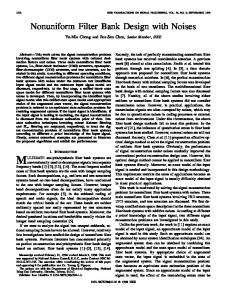
3. The Basic Principle and the Classification of Optical Fiber Sensors 3.1 The Working Principle of Reflective Optical Fiber Displacement Sensor Light emitted from the light source passes through the optical fiber transmission into the modulator, was measured under the action of some optical properties of signal light will change, such as light intensity, phase, frequency, wavelength and polarization. As shown in Figure 1, the light through the modulator becomes modulated signal light, through the photoelectric detector and signal processing circuit of follow-up, we can demodulate is measured, this is the basic principle of optical fiber sensor.
Copyright ⓒ 2015 SERSC
215
International Journal of Signal Processing, Image Processing and Pattern Recognition Vol.8, No.7 (2015)
Light source
Incident fiber
Micro bending
Modulator Emergent fiber Detector
Phase change
Polarization
B Fundamental principle of function (light transmission) fiber sensor
Light source
Spectrum Chemistry Fluorescence Ray etc.
Incident fiber
Doppler Fiber Motion of particle
Modulator Emergent fiber Detector
Intensity block
Polarization state
Fiber
Fiber
Fiber
Fiber
Figure 1. The Light through the Photoelectric Detector Signal transmission in optical fiber, light can use the following formula:
E E0 cos(t )
(1) The above formulas in E0 wave amplitude, ω is the angular frequency, which is a phase angle, from this equation, after transformation, five parameters can be obtained by the light signal. Are the strength of E02 (amplitude squared), angular frequency, wavelength
0
2 c
(c is the speed of light), phase (ωt+ψ) and polarization.
3.2 Analysis of the Geometry of Reflective Optical Fiber Displacement Sensor The chart can be 2 basic structure of optical fiber sensors, due to the light out of the optical fiber field range restriction, so the sensor can detect displacement range is limited, the receive optical fiber must be within the light cone reflecting light transmitting fiber in form or part in the cone of light in, can receive the reflected light, the optical fiber displacement sensor optical field analysis of geometry as shown in Figure 2.
216
Copyright ⓒ 2015 SERSC
International Journal of Signal Processing, Image Processing and Pattern Recognition Vol.8, No.7 (2015)
d
Receiving fiber
d
2a
Z θ 2a Transmitting fiber
Transmitting fiber image
Figure 2. Sensor Optical Field Analysis of Geometry When the receiving optical fiber located outside the light cone, will not be able to receive the optical signal, this model will fail, above can be
tan
Z 2d
(2)
According to the definition of numerical aperture of NA, numerical aperture is a parameter to measure fiber light gathering ability. From improving the coupling efficiency between light source and optical fiber perspective requirements for fiber with large NA, but the greater light mode dispersion of optical fiber is also more serious, the information transmission capacity is small.
arcsin NA
(3)
Then
d
Z 2 tan(arcsin NA)
(4)
3.3 Analysis of the Principle of Reflective Intensity Modulation Receiving optical power Pr and transmitting optical fiber Pt optical power ratio:
M
Pr Pt
(5) The intensity modulation function is influenced by many factors of a function, typical of a receiving fiber core diameter is Rr, a receiving optical fiber numerical aperture NAr, Rr sends the fiber core diameter, numerical aperture of NAt transmitting optical fiber, optical fiber and optical fiber transmitting receiving axial spacing p, reflector reflectivity δ, and a receiving fiber and reflector between the distance d. Taken together, as functions of the form can be expressed as:
M f (rr , rt , NAr , NAt , p, , d )
(6) Visible light intensity modulation function is more than the combined effects of the physical quantity results, these related physical quantities and structure parameters of the optical fiber, selection and combination of different physical quantities, will have different characteristic curves, it is suitable for different measurement range, basis of the next section will in certain assumptions on the research of intensity modulation function.
Copyright ⓒ 2015 SERSC
217
International Journal of Signal Processing, Image Processing and Pattern Recognition Vol.8, No.7 (2015)
4. Result and Discussion 4.1 The Improved Principle of Reflective Optical Fiber Displacement Sensor In this paper, the requirements of displacement sensor in the detection sensitivity are high and the volume is particularly demanding. Sensor or front belong because volume is too large to meet the requirements, or because of insufficient accuracy cannot be adopted. Therefore, this paper uses the reflection type sensors improved, as shown in Figure 3, increase a way of receiving fiber as the reference light path, in order to eliminate samesex interference effects such as the external environment.
Input Transmitting fiber
P1
Receiving fiber 1 Receiving fiber 2
P2
d
Figure 3. The Improved Reflection Type Sensors 4.2 Structure Design of Intensity Modulation Reflection Type Optical Fiber Using different combinations of optical fiber, optical structure is different, will have different response curves, the measurement and the sensitivity and dynamic range is suitable for different conditions. Over the past thirty years, in order to improve the performance of a variety of sensors, many scholars put forward different fiber structure, the main common single fiber type, fiber of type, three optical fiber type, double beam, stochastic, coaxial and semi-circular, coaxial type I, coaxial II type, double ring beam type, double beam type, coaxial random type, semicircle with models and so on. Intensity modulation characteristics such as shown in Figure 4 curves corresponding to several typical structure. f 1 Semicircle 0.8 0.6
Coaxial type Random model
0.4 0.2 0
Fiber pairs Single Fiber 500
1000
1500
2000 d ( m)
Figure 4. Intensity Modulation Characteristics in Curves Corresponding to Several Typical Structure
218
Copyright ⓒ 2015 SERSC
International Journal of Signal Processing, Image Processing and Pattern Recognition Vol.8, No.7 (2015)
Different fiber arrangement has been light intensity modulation characteristic curve of different. From the figure of the curve, we can see that different combinations, characteristic curves is dead zone length, different linear range, before the slope after slope length is different. Single fiber and fiber on the front slope of high sensitivity but linear range is small, random type, front slope sensitivity small coaxial and semicircle, but the linear range is bigger, need to choose the fiber arrangement according to the requirements of measurement. 4.3 Weak Signal Processing In order to describe the degree of signal quality, introduces two concepts, signal-tonoise ratio and improves signal-to-noise ratio. (1) Signal to Noise Ratio Signal to noise ratio refers to the useful signal components in the S effective value and the noise component of the effective value of the ratio of N.
SNR
Signal S Noise N
(7)
Measurement uncertainty or error can be expressed as:
r
1 SNR
(8)
The higher the SNR, the measurement error or uncertainty of measurement is smaller. If the signal-to-noise ratio is improved, can improve the signal-to-noise ratio to measure of the number of relations, to improve the signal-to-noise ratio is defined as
SNIR
Output SNR S / N Input SNR Si / N i
(9)
The output noise bandwidth of the system is to improve the signal-to-noise ratio and better, so, in ensuring the pass-band useful signal under the condition of the bandwidth of the system, the more narrow the better. Mainly based on the implementation of correlation detection technology is the randomness of the measured signal periodicity and noise, the measured signal generally contains the periodic component, and the noise is generally do not contain periodic components, through autocorrelation or cross-correlation operation, can effectively achieve the purpose of filtering noise. Measures of correlation is the use of correlation function, autocorrelation function and cross correlation function, detection method respectively correspond to the autocorrelation detection and correlation detection. The self-correlation function is usually used to measure associated with a random process, the autocorrelation function:
R( ) Rxx ( ) x(t ) x(t )dt
(10)
Here, put forward a kind of weak signal detection scheme, displacement sensor to realize the difference compensation, is adopted in the structure of a received two, its signal processing block diagram was shown in Figure 5.
Copyright ⓒ 2015 SERSC
219
International Journal of Signal Processing, Image Processing and Pattern Recognition Vol.8, No.7 (2015)
AC amplifier Photoelectric detector
BPF
Multiplier
LPF
Receiving fiber
Receiving fiber
Output
Driving signal
Light source
AC amplifier
Photoelectric detector
BPF
Multiplier
LPF
Figure 5. The Signal Processing Block Diagram The principle of weak signal detection theory to achieve the above diagram: drive circuit issued a certain frequencies of light, into the transmitting fiber communication to the measured object surface, the modulated signal is received by the receiving fiber, the signal is the signal being measured requires demodulation, the measured signal through band-pass filter, filter out of band noise, after correlation detection to detect weak signal, correlation detection is implemented through a multiplier and low-pass filter, the final result of the DC control signal, the two signal phase, the results obtained shows that the size of the measured displacement. 4.4 Analysis of Experimental Results The micrometer displacement measurement platform in a rotating to change the distance optical fiber probe to the reflecting surface, so that it can be measured by displacement of a different point, get the voltage displacement curve of the sensor, as shown in Figure 6. In the figure, the solid line shows the displacement voltage curve, in order to verify the accuracy of the micro controller ADUC812 work, we also measured in into the micro controller before the two analog signal after signal processing, which are marked with an asterisk curve is measuring coaxial reflection optical fiber beam signal obtained with the plus sign, the curve is measurement of random type of reflective optical fiber bundle is obtained. The measured curve and graph into two signals after dividing the match, indicating that the micro design of peripheral circuit and software of the controller is correct. Take the measurement range is 0.2mm1.2mm are linearized, the range can be obtained for the voltage displacement curve of 1mm, as shown in Figure 7. The sensitivity is 5mV/1um, linearity is less than 1%. Some experimental results show that this sensor can meet the basic technical indexes design. 0.8
0.8
0.6
0.6
0.4
0.4
0.2
0.2
0
0
-0.2
0
20
40
60
80
100
-0.2
0
20
40
60
80
100
Figure 6. The Voltage Displacement Curve of the Sensor
220
Copyright ⓒ 2015 SERSC
International Journal of Signal Processing, Image Processing and Pattern Recognition Vol.8, No.7 (2015)
1.2 1
E
0.8 0.6 0.4 0.2 0 0
0.2
0.4
0.6
0.8
1
s
Figure 7. The Range Obtained for the Voltage Displacement Curve of 1mm According to the design of the signal processing circuit, design of analog signal processing circuit, and the results of the signal processing circuit. The optical fiber sensor probe is fixed on the 2D jogging platform, because of the particularity of reflective light displacement sensor, here need to ensure that the probe perpendicular to the test surface, otherwise it will affect the output results. The test pieces is made from aluminium block surface smooth, read the output voltage value using the oscilloscope, by adjusting the two-dimensional platform, can change the probe and the distance between the test pieces.
5. Summary In the information age, along with the human understanding, expand the scope of activities to the infinite, extreme and new field in space and time, Admiral, development to develop sensing various strong, high, weak, sensor and edge effect has become a starting point for a variety of emerging areas, key projects and breakthrough. These emerging areas and key engineering process the break will bring immeasurable progress to human science and technology, produce the enormous economic benefits. Therefore, the sensor has become a pioneer in development of modern science and technology. This paper is about the design and development of reflective intensity modulated fiber optic displacement sensor for measuring micro displacement. In order to weak signal detection of optical fiber displacement sensor, puts forward a method of weak signal detection, and completed the design of the circuit part, focuses on the design of filter circuit, the amplitude detection circuit, the circuit simulation software has also been a good result, finally completed the debugging of the signal processing circuit board, and with the completion of the displacement measurement with optical fiber probe, the corresponding results obtained, the results may make analysis.
Acknowledgements This work is supported by Cooperation of Industry, Education and Academy from Longyan College (series no. LC2013001 and LC2013004)
References [1]
[2] [3]
Y. C. Su, C. C. Chang and J. L. Wang, "Construction of an automated gas chromatography/mass spectrometry system for the analysis of ambient volatile organic compounds with on-line internal standard calibration", Journal of Chromatography A, vol. 1201, no. 2, (2008), pp. 134-140. Z. Li, E. Sahle-Demessie, A. A. Hassan and G. A. Sorial, “Transport and deposition of CeO2 nanoparticles in water-saturated porous media", Water Research, vol. 45, no. 15, (2011), pp. 4409-4418. N. Goldovsky and V. Goldovsky, “Correlational gas analyzer”, Measurement, vol. 33, no. 3, (2003), pp. 273-279.
Copyright ⓒ 2015 SERSC
221
International Journal of Signal Processing, Image Processing and Pattern Recognition Vol.8, No.7 (2015)
[4] [5] [6]
[7]
[8] [9] [10]
[11]
[12] [13] [14]
J. W. Leonhardt, “A new ppb-gas analyzer by means of GC–ion mobility spectrometry (GC-IMS)”, Journal of Radioanalytical and Nuclear Chemistry, vol. 257, no. 1, (2003), pp. 133-139. J. Wang, R. Wang and D. Q. Miao, “Data enriching based on rough set theory”, Journal of Environmental Sciences, vol. 29, no. 3, (2010), pp. 63-69. C. Hou, J. J. Li, D. Huo, X. G. Luo, J. L. Dong, M. Yanga nd X. J. Shi, " Design of an embedded gas detector based on spectral analysis ", Chinese Journal of Scientific Instrument, vol. 29, no. 4, (2008), pp. 471-475. A. Fort, M. Mugnaini, S. Rocchi, V. Vignoli, E. Comini and A. Ponzoni, " Metal-oxide nanowire sensors for CO detection: characterization and modeling ", Sensors and Actuators B: Chemical, vol. 148, no. 1, (2010), pp. 283-291. M. Breysse, B. Claudel, L. Faure, M. Guenin and R. J. J. Williams, " Chemiluminescence during the catalysis of carbon monoxide oxidation on athoria surface", J. Catal, vol. 45, no. 2, (1976), pp. 137-144. X. A. Cao, Y. Tao, L. Li, Y. H. Liu, Y. Peng and J. W. Li, " An ethyl acetate sensor utilizing cataluminescence on Y2O3 nanoparticles", Luminescence, vol. 26, no.1, (2011), pp. 5-9. L. Tang, Y. M. Li, K. L. Xu, X. D. Hou and Y. Lv, " Sensitive and selective acetone sensor based on its cataluminescence from nano-La2O3 surface", Sensors and Actuators B: Chemical, vol. 132, no.1, (2008), pp. 243-249. X. A. Cao, Z. Y. Zhang and X. R. Zhang, "Sensitive a A novel gaseous acetaldehyde sensor utilizing cataluminescence on nanosized BaCO3", Sensors and Actuators B: Chemical, vol. 99, no.2, (2004), pp. 30-35. Z. M. Rao, L. J. Liu, J. Y. Xie and Y. Y. Zeng, "Development of a benzene vapour sensor utilizing chemiluminescence on Y2O3", Luminescence, vol. 23, no. 3, (2008), pp. 163-168. H. Cao, Y. Chen, Z. Zhou and G. Zhang, “General models of optical-fiber-bundle displacement sensors”, Microwave and Optical Technology Letters, vol. 47, no. 5, (2005), pp. 494-497 G. Zhang, Y. Chen and H. Cao, “Design of an embedded optical fiber micro-displacement measurement system”, in: Proceedings of SPIE, vol. 6150 I, (2006). 61501M.
Authors Junjie Yang, he received the Dipl.-Ing. degree in Optic from Fujian normal University, Fuzhou, China, in 2009 and now as a Ph.D. student in the Department of Mechanical and Electrical Engineering, Xiamen University, Xiamen, China.
Wenxiang Chen, he is currently a Professor in the Department of Mechanical and Electrical Engineering, Xiamen University, Xiamen, China, he has considerable expertise in the areas of sensing, and power electronics.
222
Copyright ⓒ 2015 SERSC