Sensors & Transducers, Vol. 169, Issue 4, April 2014, pp. 211-216
Sensors & Transducers © 2014 by IFSA Publishing, S. L. http://www.sensorsportal.com
Study on Speed-sensorless Vector Control System for Mining Electric Locomotive Based on ARM Zhu Yuqin Electrical and Information Engineering College, Huainan Normal University, Huainan, 232038, China E-mail:
[email protected]
Received: 9 April 2014 Accepted: 27 April 2014 Published: 30 April 2014 Abstract: The filthy and wet environment of coal mines has always been unfavorable to the proper functioning of electric locomotive. It usually suffers from limited speed feedback signal because the speed sensor is flooded with water and stopped, resulting in its malfunctioning. It often deviates from its track, crashes, or incurs other accidents. To solve these problems, this study employs an embedded processor (i.e., ARM) as the control core to design a speed -sensorless. Vector control system for electric locomotive. A vector estimation method of magnetic linkage and rotational speed of rotor is also provided. In addition, the rationality of the system hardware design and the correctness of the estimation method are verified. Copyright © 2014 IFSA Publishing, S. L. Keywords: Speed –sensorless, Vector estimation, Simulation, ARM; Electric locomotive.
1. Introduction Mining electric locomotive is the main transportation equipment in mine production. However, the local electric locomotive lags behind the international and advanced ones in terms of control technique. Currently, old flameproof direct current motor is used as the driving force. By contrast, this study adopts a series motor. Specifically, camshaft contactor group and digital optical pulse encoder are used for startup and speed adjustment to change the direction of the magnetizing current, and consequently, the rotation direction of the motor. The inefficient control technique of mining electric locomotive is due to its complicated structure, high cost, unsatisfactory reliability, and difficult maintenance. Thus, the electric locomotive fails to meet the requirements of the unfavorable environment of coal mines. Electric locomotive suffers from limited signal output because the speed
Article number P_RP_0105
sensor is flooded with water, resulting in its malfunctioning. Therefore, this study designs a speed-sensorless vector control system for mining electric locomotive based on ARM9E-S to overcome the negative effects of the filthy and wet environment of coal mines as well as to address the abovementioned problems.
2. System Hardware ARM9E-S is a newly released ARM9 series by the ARM Company of England. It is characterized by high performance and low power consumption. It is an embedded microprocessor with a 32-bit dual instruction set and a 5-level pipeline organization. It has a built-in analog-to-digital (A/D) converter, a digital filter, a pulse width modulator (PWM), and many input–output interfaces, which allows it to considerably shorten the design time and reduce the
211
Sensors & Transducers, Vol. 169, Issue 4, April 2014, pp. 211-216 cost. Therefore, this study uses ARM9E-S as the control core of the system to take advantage of its rich resources, optimize its hardware structure, and improve the stability and reliability of the system. The use of ARM9E-S not only improves the working
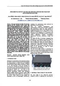
efficiency of the system but also reduces the cost. Fig. 1 shows the overall diagram of the hardware. Its periphery circuit covers drive chip IR21363S, LCD touch screen, rectifier filter circuit and a smallest system.
Fig. 1. Overall diagram of the hardware.
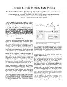
3. Speed-sensorless Vector Control Strategy for Electric Locomotive To address the low reliability of the existing speed sensor, a speed-sensorless vector control strategy is applied, in which the algorithm facilitates the easy derivation of the rotational speed vector of the motor after processing the voltage and current signals of the motor rotor. The key to this problem is to determine how to estimate rotational speed massages rapidly and maintain higher control accuracy to meet the requirements of real-time control. Therefore, this study designs an innovative control system (Fig. 2). In this system, the set speed value ωref is controlled by a proportional integral (PI) controller and a weak magnetic conditioning stimulus, where the current reference value is the
output. After the current PI control, the voltage reference values (uds, uqs) are the output. Thereafter, the voltage values (uαs, uβs) are generated via Park inversion to drive the space-vector SVPWM to send six-way PWM control signals to the three-phase inverter. The sampled voltage Udc is reconstructed by phase voltage to output voltage (u’αs, u’βs), and the sampled currents (iA, iB) are inverted by Clarke to output currents (iαs, iβs), which are sent to the flux observer for field orientation and magnetic linkage estimation (Fig. 2). The estimated magnetic linkage and currents (iαs, iβs) are then sent to the modelreference adaptive system (MRAS) for rotor speed and parameter estimation. Moreover, the estimated magnetic linkage, rotational speed, and inverted current contribute to the close-loop speed control.
Fig. 2. Diagram of the speed-sensorless vector control strategy for electric locomotive.
212
Sensors & Transducers, Vol. 169, Issue 4, April 2014, pp. 211-216
3.1. Field Orientation of Rotor This study proposes an innovative strategy, that is, the speed-sensorless vector control strategy, as an alternative to the traditional speed sensor control by comprehensively considering the environment and conditions of mining electric locomotive. This proposed strategy aims to allow the motor rotor to rotate at any angular velocity ωr in the coordinate system dq (Fig. 3).
is
isq
isd
( r ) r
Fig. 3. ABC and dq coordinate systems of the stator and the rotor, respectively.
For the vector direction of the magnetic field of the rotor ψr to coincide with d axle and for q axle to exceed 90 ° rotor ψr, the projection of magnetic linkage ψr on q axle is set to 0. That is, ψrq =0, ψrd =ψr. Rotor voltage equation:
d r 0 R r ird dt 0 R r i r q ( r )
(1) ,
r
Magnetic linkage equation of rotor:
r
Lm i sq r Lr ,
(2) ,
(3)
r Am r Bm is , Tr wr
(4)
Eq. (4) reveals that the magnetic linkage of rotor ψr is only controlled by the component of the stator current in d axle isd. Moreover, Eq. (3) reveals that when the rotor field ψr is unchanged, the torque of the motor is only controlled by the component of the
(5)
wr L 0 Bm sd . Tr 0 Lmd
where Am
,
To ensure the global asymptotic stability of the system, self-adaptation law of model parameters can be established to produce a mathematical model in which the speed identification value converges with the actual value. (6)
According to the Popov Ultra stability theorem, two conditions for global asymptotic stability are deduced. First, an integral inequality should exist. t
e Wd 0
To insert Eq. (1) into Eq. (2) and eliminate ird, the following is obtained. d r R r ( L m i sd r ) dt Lr ,
In a rotor field oriented vector control system, the rotor magnetic linkage vector needs to be estimated to realize speed estimation and field orientation. The rotor magnetic linkage voltage and current models observations reveal that no rotational speed ωr with a known measured value exists in both models. Therefore, by using the current and voltage models as the adjustable and reference models, respectively, the adaptive model parameters and adjustable model state error can be modified to obtain the real approximation speed of motor ώ. We suppose that the equivalent mutual inductance of the stator and rotor (Lmd) and the stator winding inductance (Lsd) are set values in the rotor magnetic linkage current model, the rotational speed required for identification is ŵr, and the time constant of the rotor is Tr. Tr is changed with the increase in temperature and change of saturable magnetic circuit. Therefore, Tr is a parameter to be identified. Flux linkage is shown as follows:
0
Torque equation:
Te n p
3.2. Speed Estimation
t wr 1 (e, t , )d 2 (e, t ) ,
L m isd L r ird
0 L m i s q L r i r q
stator current in q axle iqs. Thus the vector direction of motor field is confirmed.
t
2 0
,
(7)
Second, all elements in (SI-A)-1 should be positive real values. Eq. (6) and (7) are combined to obtain the following.
t Wr 0 K i (ru ri ru ri )d , K p (ru ri ru ri )
(8)
where Kp ≥ 0, Ki ≥ 0. According to Eq. (8), the MRAS for rotor speed and parameter estimation can be constructed (Fig. 4).
213
Sensors & Transducers, Vol. 169, Issue 4, April 2014, pp. 211-216
Fig. 4. Model-reference adaptive system for rotor speed and parameter estimation.
For the speed estimation system, the error increases at low speed, whereas weak state error and overshooting exist at high speed. Therefore, at low speed, Kp and Ki are increased to shorten the convergence time and speed up the response; meanwhile, at high speed, Kp and Ki are reduced slightly to weaken state error and overshooting. This position is established to obtain the mathematical model with the estimation of speed change by Kp and Ki (MRAS): Kp 50 Kp K p w r
wr 50 wr 50
wr 150 Ki Ki K i K1 ( wr 150) wr 150
4.1.1. No-load Start and on-load Running of Motor Fig. 5 shows the no-load start of the motor at a rated voltage. Fig. 6 presents the on-load running of motor. The figures reveal that the rotational speed increased when the motor is started; thereafter, the rotational speed reaches its peak of 1200 r/min at 0.2 s. At 0.5 s, 152 Nm is loaded suddenly, and the rotational speed drastically decreases.
(9)
(10)
Eq. (9) shows that when the rotational speed is ŵr 50 r/min, Kp gradually reduces with the increase of the rotational speed. Eq. (10) reveals that when the rotational speed 150 r/min, Ki will be changed with the change of rotational speed.
4. Simulation of the Model Parameter Self-adaption Speed Estimation Based on MRAS The speed-sensorless vector control system simulation model is constructed in Matlab’s Simulink to verify the feasibility of the designed rotational speed parameter self-adaption identification model. In the simulation diagram, the parameters of the motor are UN = 220 V, fN = 50 Hz, PN = 22 kW, nN = 1200 r/min, TN = 40 Nm and the connection is Y.
214
4.1. Analysis on Simulation Waveforms
Fig. 5. Rotational speed of the motor.
Fig. 6. Torque of the motor.
The applied load is considerably higher than the rated load of the motor (40 Nm). The rotational speed decreases to 0 r/min at 1.45 s, and eventually becomes a negative value. This phenomenon is termed as reversion. However, in the running process of the entire system, the speed follows property predictable trend. Therefore, the estimation accuracy is improved when the operation of the motor is stable.
Sensors & Transducers, Vol. 169, Issue 4, April 2014, pp. 211-216
4.1.2. Comparison between the Estimated and the Simulated Speed Figs. 7 and 8 show the estimated and the measured speed, respectively. The estimated speed fluctuates slightly, whereas the measured speed proceeds smoothly. The minimal difference between them verifies the correctness of the estimation method for rotational speed.
Fig. 7. Wave form of the estimated speed.
The above comparison and analysis of the simulated waveforms verify that the designed parameter self-adaption model planning is effective and feasible.
5. Experimental Results and Analysis This system is connected with the simulator (ULINK) via USB plug, and JTAG interface is connected with the ARM9E-S control panel. The current and voltage signals detected by the external detection circuit are sent to the A/D interface of ARM9E-S. The SVPWM signal sent by ARM9E-S enters the driver (IR21363S) to drive the output voltage of the three-phase inverter and adjust the 400 W three-phase asynchronous motor in the laboratory (Fig. 1). The experiment parameters are PN = 400 W, UN = 220 V, IN= 2A, nN = 1200 r/min, and the connection is . Under laboratory conditions, the output phase voltage values of the motor are obtained at different frequencies. Fig. 11 and 12 show the output voltage values at 20 Hz and 80 Hz, respectively.
Fig. 8. Waveform of the rotational speed of the measurement module.
Fig. 9 and 10 present the output speed of the motor when the estimated and the measured speed are regarded as the feedback signal, respectively. The waveform of the output speed when the estimated speed vector is used as the feedback signal is nearly the same as that when the measured speed vector is used.
Fig. 9. Waveform when the estimated speed is used as the feedback signal.
Fig. 10. Waveform when the output speed of the measurement module is used as the feedback signal.
Fig. 11. Motor phase voltage at 20 Hz.
Fig. 12. Motor phase voltage at 80 Hz.
The waveforms in Fig. 11 and 12 reveal that the output voltage values of this system at different frequencies are more stable and do not have severe distortion and deformity. The glitches in the figures are caused by the oscillograph and the parameters of the motor and are not caused by any system design problem. The motor is controlled by the system. Figs. 13 and 14 show the output speed at no-load and suddenload conditions. The output waveform at no-load is
215
Sensors & Transducers, Vol. 169, Issue 4, April 2014, pp. 211-216 stable and smooth, whereas that at sudden load has a sudden change with rapid dynamic response but will eventually normalize.
estimation accuracy. It obtains flux linkage and rotational speed estimation in full-speed range. The MRAS model simulation and the system experiment results prove that the proposed system presents immediate response, is stable, has dynamic characteristics, and renders accurate speed estimation.
Acknowledgements
Fig. 13. Rotational speed of the motor at no load.
I thank Natural Science Funding Organization of Anhui Province Education Department for me to sponsor. My project serial number is KJ2012Z376.
References
Fig. 14. Rotational speed of motor at sudden load.
The above comparison and analysis of the experimental waveforms confirm that the designed system is stable and reliable and offers correct estimation.
6. Conclusion Problems in the actual use conditions of electric locomotive in the country prompted this study to design a speed-sensorless vector control system for mining electric locomotive based on ARM9E-S. This study uses the newly released ARM9E-S by ARM Company of England as the system processor instead of the existing single-chip processor. It overcomes the disadvantages of the design of the traditional hardware, shortens the design time, and reduces the cost. Moreover, it is capable of realizing complicated speed vector estimation and control. During the design phase of rotor linkage and speed estimation, it surpasses the limitations of the compensation voltage model by using the proposed model to increase the
[1]. Feng Duosheng, Zeng Yuenan, Speed Sensorless Vector Control Principle and Practice, China Machine Press, 1997. [2]. Wang Chengyuan, Xia Jiakuan, Sun Yibiao, Modern Motor Control, China Machine Press, Beijing, 2012. [3]. Lin Fei, Du Xin, MATLAB Simulation of Power Electronics Application Technology, China Electric Power Press, Beijing, 2009. [4]. Wang Bin ,Wang Yue, Wang Zhao-an, Direct torque control of permanent magnet synchronous motor drives using space vector modulation, Electric Machines and Control, Issue 6, 2010, pp. 45-50. [5]. Xue Yu-Qiang Liu Bin, Analysis of zero state vector distribution based on space vector PWM, Electric Machines and Control, Issue 8, 2010, pp. 93-97. [6]. Li Jian, Cheng Xiao-Hua, Online identification based on model reference adaptive system for stator resistance of induction motor, Electric Machines and Control, Issue 6, 2007, pp. 620-624. [7]. Li Ruijin, Jin Lin et al., Design of Frequency Control System Based on ARM SVPWM Battery Locomotive Electric Machines & Control Application, Issue 10, 2012, pp. 34-38. [8]. Li Zhai, Hefei Li, Modeling and simulating of SVPWM control system of induction motor in electric vehicle, in Proceedings of the IEEE International Conference on Automation and Logistics (ICAL'08), Wuhan, China, 2008, pp. 2026-2030. [9]. Ban Yi et al, Design of Adaptive Mine Fan Monitoring System Based on ARM9, Modern Electronics Technique, Issue 6, 2011, pp. 129-130. [10]. Ma Zhong Mei et al., Principles and Applications of TI Microcontroller with ARM Cortex Core, Beijing, 2011.
___________________
2014 Copyright ©, International Frequency Sensor Association (IFSA) Publishing, S. L. All rights reserved. (http://www.sensorsportal.com)
216