Paper #6529-18, Proceedings of the, SPIE Smart Structures and Materials Symposium, San Diego, CA, March 19-22, 2007
SPIE Copyright © 2007
Subsurface Sampler and Sensors Platform Using the Ultrasonic/Sonic Driller/Corer (USDC) Yoseph Bar-Cohen, Stewart Sherrit, Xiaoqi Bao, Mircea Badescu, Jack Aldrich and Zensheu Chang Jet Propulsion Laboratory (JPL)/Caltech, Pasadena, California, USA, E-mail:
[email protected] Web: http://ndeaa.jpl.nasa.gov
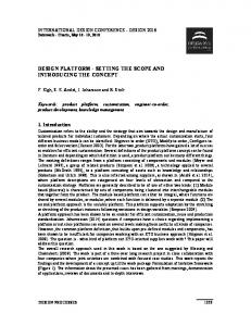
ABSTRACT The search for existing or past life in the Universe is one of the most important objectives of NASA’s mission. For this purpose, effective instruments that can sample and conduct in-situ astrobiology analysis are being developed. In support of this objective, a series of novel mechanisms that are driven by an Ultrasonic/Sonic actuator have been developed to probe and sample rocks, ice and soil. This mechanism is driven by an ultrasonic piezoelectric actuator that impacts a bit at sonic frequencies through the use of an intermediate free-mass. Ultrasonic/Sonic Driller/Corer (USDC) devices were made that can produce both core and powdered cuttings, operate as a sounder to emit elastic waves and serve as a platform for sensors. For planetary exploration, this mechanism has the important advantage of requiring low axial force, virtually no torque, and can be duty cycled for operation at low average power. The advantage of requiring low axial load allows overcoming a major limitation of planetary sampling in low gravity environments or when operating from lightweight robots and rovers. The ability to operate at duty cycling with low average power produces a minimum temperature rise allowing for control of the sample integrity and preventing damage to potential biological markers in the acquired sample. The development of the USDC is being pursued on various fronts ranging from analytical modeling to mechanisms improvements while considering a wide range of potential applications. While developing the analytical capability to predict and optimize its performance, efforts are made to enhance its capability to drill at higher power and high speed. Taking advantage of the fact that the bit does not require rotation, sensors (e.g., thermocouple and fiberoptics) were integrated into the bit to examine the borehole during drilling. The sounding effect of the drill was used to emit elastic waves in order to evaluate the surface characteristics of rocks. Since the USDC is driven by piezoelectric actuation mechanism it can designed to operate at extreme temperature environments from very cold as on Titan and Europa to very hot as on Venus. In this paper, a review of the latest development and applications of the USDC will be given. 1. INTRODUCTION NASA exploration missions are increasingly involved in-situ sampling and analysis of various planets in the solar system. For this purpose, effective instruments that can sample and conduct in-situ astrobiology analysis are being developed. Existing drilling techniques are limited by the need for high axial forces and holding torques, high power consumption without ability to efficiently duty cycle, and they also require heavy equipment. To address these limitations, the JPL’s Advanced Technologies Group [http://ndeaa.jpl.nasa.gov] and engineers from Cybersonics, Inc. jointly developed the USDC [Bar-Cohen et al., 1999; Bao et al., 2003; http://ndeaa.jpl.nasa.gov/nasande/usdc/usdc.htm]. Following the development of this novel mechanism (see Figure 1) the team conceived many innovative designs that were disclosed in NASA New Technology Reports and patents [Aldrich et al, 2006; Bao et al. 2004; Bar-Cohen et al. 1999; Bar-Cohen et al. 2001; Bar-Cohen et al 2002; Bar-Cohen et al. 2003; Bar-Cohen et al. 2003a; Bar-Cohen et al. 2003b; Dolgin et al. 2001a; Dolgin et al 2001b; Sherrit et al. 2001; Sherrit et al 2002; Sherrit et al. 2003; Sherrit et al. 2006]. The USDC requires low axial force, thereby overcoming one of the major limitations of planetary sampling using conventional drills in low gravity environments. This capability offers the advantage of being able to perform tough tasks of drilling and coring in hard rocks, ice and packed soil using relatively small force and relatively lightweight hardware. The USDC was demonstrated to: 1) drill ice and various rocks including granite, diorite, basalt and limestone, 2) not require bit sharpening, 3) operate at low and high temperatures, and 4) operate at low average power using duty cycling. The capabilities that are being investigated include probing the ground to select sampling sites, collecting various forms of samples (including cores and powdered cuttings), sampling long cores of hard basalt using low power and hosting sensors for measuring various properties. A series of modifications of the USDC basic configuration were made resulting in the development of the Ultrasonic/sonic Rock Abrasion Tool (URAT), Ultrasonic/Sonic Gopher for deep ice drilling, the Lab-on-a-drill and many others.
The USDC is made of three key components: actuator, free-mass and bit (see Figure 1) [Bao et al, 2003]. The actuator operates as a hammering mechanism that hits the free-mass and in turn the bit is hit to fracture the rock that is in contact with the bit. The actuator consists of a piezoelectric stack with backing for forward power delivery and a horn for amplification of the induced displacement. The USDC is actuated by a piezoelectric stack that is driven in resonance and is held in compression by a stress bolt that prevents its fracture during operation. In the basic design the piezoelectric stack has a resonance frequency of about 20-kHz. Unlike typical ultrasonic drills where the bit is acoustically coupled to the horn, in the USDC the actuator drives a free flying mass (free-mass), which bounces between the horn tip and the drilling/coring bit converting the ultrasonic impacts to hammering at sonic frequencies. The impacts of the free-mass create stress pulses that propagate to the interface of the bit and the rock onto which the USDC is placed in contact. The rock is fractured when its ultimate strain is exceeded at the rock/bit interface.
FIGURE 1: A photographic view of the USDC showing its ability to core with minimum axial force (left), and a schematic diagram of its cross-section (right).
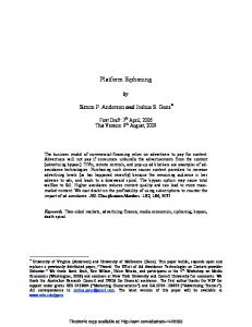
2 ANALYTICAL MODELING THE OPERATION OF THE USDC Coring via the USDC mechanism involves rock fracture via impact loading (percussion). To better understand the fracture of rocks under impact loading, a finite element model using ANSYS (a finite element software package) was developed to investigate the propagation of the induced stress. Results were derived by assuming that the rock medium is made of isotropic material with a Young's modulus of 10 GPa and Poisson’s ratio of 0.3. Contour maps of the maximum principal strain were plotted and used to indicate the areas where the rock is fractured and to determine how the elastic waves propagate in the rock prior to fracture. This analytical capability allows for an estimate of the limitations on the diameter of the cored material that maintains structural integrity. Using this analysis, it is estimated that the minimum diameter of intact cores that can be produced is about 4-5 mm for medium to hard materials. The drilling rates in various rocks at 10-W average power were calculated and a graph is shown in Figure 2 for various rock stiffness values. This capability to predict the performance of the drill allows optimizing the design of effective USDC units. 3. LAB-ON-A-DRILL The USDC characteristics of using a bit that does not turn allows for probing and sensing in addition to sampling cores and powdered cuttings. The ultrasonic/sonic hammering action on the bit allows using it as a sounder for probing the drilled medium. Further, the longitudinal displacement of the bit without rotation allows for mounting sensors for realtime analysis of the drilled medium. The combination of sampling, probing and sensing enables the USDC to be used as a lab-on-a-drill system. 3.1 USDC with integrated sensor suite Since the USDC bit does not turn and its vibration amplitude is relatively small one can easily mount sensors on the bit and conduct real-time tests during drilling or coring. Two types of sensors were successfully demonstrated to date: thermocouple and fiberoptic. A thermocouple was used to measure the rate and maximum rise of temperature and these values were found to correlate to the hardness of the rock being drilled. Even though these thermal variables are dependent on the heat conductivity and capacity of the drilled object, one can assume with a reasonable accuracy that most rocks have thermal properties within a comparatively narrow range. Compiling temperature rise rate and maxima as a function of time for variety of drilled materials has demonstrated the feasibility of using a thermocouple-on-the-bit as a means of assessing the drilled medium hardness (see Figure 3). Also, using an optical fiber provided a sensing capability where a fiber with approximately 160 μm diameter was imbedded into 10-mm diameter coring bit with a 1-
2
mm wall thickness. Reflection data in the wavelength range of 400-1200 nm were recorded. The use of fiberoptics with UV light in the range of 200-nm wavelength may allow for identifying biological markers.
Soft Medium Hard Very hard
FIGURE 2: Analytical drilling rates in rocks with various hardness levels using 10W average power. The rocks are classified by their compression strength, where: Soft: 0 – 50; Medium: 50 – 100; Hard: 100 – 200; and Very hard: >200 (MPa).
FIGURE 3: The measured temperature maxima and initial temperature rate as a function of hardness (inverse drilling rate) for variety of media.
4. VARIOUS USDC CONFIGURATIONS 4.1 Ultrasonic/Sonic Gopher Using the USDC mechanism a Gopher was developed where the bit was as large as 6.4 cm and had a diameter that is great than the actuator [Badescu et al, 2006]. The device is shown schematically in Figure 4, where a core is formed up to the length of the internal size of the bit and it is removed from the borehole and this process is repeated till the desired depth is reached. Since it was needed to operate at low temperatures it was tested in a cold chamber for various periods as shown in Figure 5 where it was tested in as low as -60oC. To demonstrate the capability of the Gopher it was tested drill glacier ice at Mt. Hood, OR and lessons learned were implemented into the design and the enhanced Gopher was tested in Antarctica.
FIGURE 4: Schematic view of the ultrasonicgopher operating inside the borehole.
FIGURE 5: Tests of the USDC operation at low temperatures (conducted at the JPL’s Extraterrestrial Materials Simulation Laboratory)
The field test Antarctica was conducted at Lake Vida (see Figure 6) and it provided an important opportunity to demonstrate the feasibility of this technology while determining the associated challenges and requirements to enhance its capability for future drilling objectives. The unit was successfully used to reach 1.76-m deep and it was a major
3
milestone since it is significantly deeper than the length of the whole Gopher with its support elements. studies, efforts will be made to reach as deep as 100-m, while performing the drilling autonomously.
In future
FIGURE 6: Lake Vida, Antarctica, test site (left) and the milestone 1.76-m deep drilled borehole 4.2 Packed Soil Penetrator Recent, a challenged was posed to penetrate packed soil to penetrate about 1 meter using 1/8” – 3/16” diameter probes via low axial load. The use of push rod requires a force of several hundreds pounds which would easily result in buckling of the probe. A novel Ultrasonic/Sonic Impacting Penetrator (USIP) was developed and demonstrated to greatly reduce the required push force. In demonstration of the USIP capability it was shown that the required push force to penetrate highly packed soil down to about 1-meter was reduced from 200 lb to 7 lb. A graphic view of the developed unit is shown in Figure 7. This effort involved both modal and impact analysis, where the modal analysis was used to determine the dimensions of the horn and backing for a required resonance frequency range. The results of this analysis were also used to adjust the dimension of the ultrasonic horn so that the neutral plane matches the mounting plane to avoid effects of the transducer vibration on the actuator support structure. The impact analysis, which determines the interaction between the free-mass and the ultrasonic horn, was used to derive an optimal weight of the free-mass.
FIGURE 7: A schematic view of the disclosed USIP. 4.3 Ultrasonic/Sonic Anchor To support requirements for anchoring of legged and wheeled rovers, inflatable structures and landers the USDC offers significant advantages in its ability to operate view low axial load. Such a capability using low mass device and relatively low power is needed to support platforms that would operate in low gravity environments and from steep mountains in rugged extraterrestrial terrains. A U/S Anchor was designed and fabricated using a modification of the USDC mechanism which drills at an angle with the normal to the surface. Operating the hammering action of the USDC in reverse allows its extraction from the medium onto which it was anchored and avoids possible jamming. 5. USDC WITH VARIOUS NOVEL HORNS The horn is an important part of the USDC actuator amplifying the produced vibration amplitude. Generally, the horn is made as a step down diameter from the one that the piezoelectric stack has and thus gaining from the related reduction in the surface areas.
4
5.1 Dog-bone shape horn Recently, a dog-bone design was introduced and demonstrated to improve the drilling performance as well as a benefit for mounting bits as well as operating with dual free-mass to operate both forward and in reverse. For this purpose, various horn designs were examined analytically and compared to conventional and solid shape horns and analytically it was shown that the dog-bone design has a superior performance. To demonstrate the capability of the dog bone horn a finite element modeling was used to determine the control parameters and showed the excitation of superior tip displacement and velocity. A view of the U/S gopher using the dog bone horn is shown in Figure 8 (bottom of the item on the right).
FIGURE 8: A view of the new USG with a dog bone horn.
5.2 Folded horn The length of the horn in the USDC actuator can be a concern when there are volume constrains and reduction of its size can be critical to the integration of the unit as a sampler. A compact shape horn was developed with hollow configuration that amplifies vibrations of high power actuation mechanisms as shown in Figure 9. This folded horn can be configured in axis-symmetric and planar shapes to provide manufacturing options. The use of reflectors at the folds allows for control of the phase of the reflected strain wave and for the introduction of constructive bending vibrations that enhance the amplification of the actuation.
FIGURE 9: A schematic view of the cross section of a folded horn
6. USDC WITH VARIOUS BITS 6.1 Ultrasonic/Sonic Rock Abrasion Tool (URAT) Abrasion of the surface of a rock using low axial force and limited average power is needed to remove weathered layers from rock surfaces and expose pristine sections. Conventional rotating mechanisms require high axial loads and they are involved with contamination sources such as lubricants and ground filings from their motor gearbox. The use of the USDC offers significant advantages in requiring low axial force, low average power, low number of components, and the capability to produce a mechanism of removal of powered cuttings from the borehole. In its original form, the USDC was designed to drill or core and it is not was not designed to remove layers of weathered material from rocks. To address the need for an abrasion tool an Ultrasonic Rock Abrasion Tool (URAT) was developed. For this purpose, an abrasion bit was designed similar to the hammering surface of a meat tenderizer. Teeth were machined onto the bottom of the disk that is part of the abrasion bit. These teeth amplify the drilling pressure and enhance the action of the URAT. A schematic cross-section drawing is shown in Figure 9 illustrating the components and the compact structure of the URAT. A view of abraded basalt is shown in Figure 10. The abrasion tool consists of a 1.6 in. (40-mm) diameter disk that is attached to a shank that fits around the horn. The free-mass is placed inside the shank between the horn and the bottom of hole along the inner part of the bit. On the bottom of the disk teeth were machined in the form of pins that stick out of the disk. 6.2 Interchangeable bit One of the most promising benefits of the USDC is the simple interface it provides to the bit, and the simplicity of the shape of the bit itself. The use of multiple bits is essential as it is simply not practical to accomplish the multitude of
5
tasks envisioned to be feasible to obtain with the USDC. These tasks can, however, be accomplished by a single actuator that utilizes multiple bits for drilling, coring, surface preparation, and sampling, where the bits can be exchanged as needed. The bit does not require sharpening, but, if a bit where to get damaged for whatever reason, it could simply be replaced.
FIGURE 9: Schematics of the Ultrasonic Rock Abrasion Tool (URAT)
FIGURE 10: Photographic view of a basalt that was abraded by the URAT. The footprint of the abrasion bit can be seen on the surface.
6.3 All in one bit The use of multiple bits requires a manipulation system to exchanging bits as needed. If a manipulation system is not available it is highly desirable accomplish as many functions as possible using a single bit. For this purpose, an all-inone bit was developed and demonstrated. The bit is shown schematically in Figure 11 and it consists of a tube with a wedge at the top of the inner surface of the bit, a set of springs near the tip and a push rod that is inserted thru a center hole in the bit. Once a core is produced at a length of the inner section of the bit, the wedge introduces transverse forces at the top of the core to cause maximum stress near the root and shear fracture. The side springs hold the produced core for removable from the borehole and the core is extracted when needed using the push rod from the top of the bit.
FIGURE 11: A schematic view of the core extraction bit.
6.4 Powdered cuttings sampler In the authors prior development of powder cuttings samplers, they have shown that the USDC offers significant advantages in requiring low axial force, low average power, low number of components, and capability to produce powered samples directly from rock [Sherrit et al, 2003; Sherrit et al, 2006]. However, the previous designs required using rock fragments that are inserted into the crushing section of the device [Sherrit et al 2002] or required pressurized gas to transport the powder from the sampled rock [Sherrit et al 2003]. In a recent modification, the authors used trapping holes that acquire the upward traveling powder that enter a hollow inner section of the bit and retains the particles until they need to be removed. Using modeling analysis that the authors developed for the planar folded horn configuration [Chang et al 2004] a compact sampler weighing 265-g was designed as shown schematically in Figure 12. A hollow bit was made with an end-effector section that is brazed on the bit and has teeth to enhance the cutting performance. The bottom of the bit was made with holes that allow for the penetration of the produced cuttings to enter into the hollow section. In order to trap the powder, the holes were made with a narrower section on the bottom such that the odds of exiting the hole once the powder enters the trap are minimized. Tests of the powder that is produced by USDC based mechanisms have
6
shown that it does an outstanding job of generating powders for high quality X-ray diffraction spectra [Blake et al, 2003 and Chipera et al, 2003]. XRD patterns obtained from USDC generated powder essentially indistinguishable from powders that were obtained using a laboratory Retsch mill. Also, the particle size distributions are quite comparable to the costly standard laboratory Retsch mills.
FIGURE 12: Various photographic views of the bit: Left: bit bottom with the holes; Middle: Side view; and Right: The bit drilling limestone. 7. SUMMARY The ultrasonic/sonic driller/corer (USDC) is investigated for various potential planetary applications. To allow effective design and construction of the various modifications of the USDC an analytical model was developed to predict its behavior towards the goal of optimizing its performance. Physical models were developed for each section of the device and their interactions. The developed models were integrated to allow investigation of the various interactions of the USDC and effective designs to support various applications. Various designed were developed and demonstrated including the Lab-on-a-Drill, Ultrasonic Gopher, soil penetrator and many others and various configurations of the horn and the bit were used to provide multifuncitonality. The Lab-on-a-Drill is intended to take advantage of the probing capabilities of the USDC, the capability to sample cores and powdered cuttings as well as the fact that sensors can be easily mounted on the bit and allow real time data acquisition while drilling. The URAT was demonstrated to remove rock layers from as hard as Basalt. The Ultrasonic Gopher operates in a cyclic mode of coring, uploading, core caching and downloading. This device was demonstrated to drill in ice at Antarctica reaching about 1.76-meter deep. The potential of the USDC is continuing to be investigated with goal of taking the most benefits from its potential. ACKNOWLEDGEMENT Research reported in this manuscript was conducted at the Jet Propulsion Laboratory (JPL), California Institute of Technology, under a contract with the National Aeronautics and Space Administration (NASA). REFERENCES Aldrich J., S. Sherrit, M. Badescu Y. Bar-Cohen, X. Bao, and Z. Chang, “Controller using extremum-seeking to drive heavily perturbed electroactive actuators at resonance” NASA New Technology Report (NTR), Docket No. 43519, (February 9, 2006). Badescu M., S. Sherrit, A. Olorunsola, J. Aldrich, X. Bao, Y. Bar-Cohen, Z. Chang, P. T. Doran, C. H. Fritsen, F. Kenig, C. P. McKay, A. Murray, S. Du, T. Peterson, and T. Song, “Ultrasonic/sonic Gopher for subsurface ice and brine sampling: analysis and fabrication challenges, and testing results,” Proceedings of the SPIE Smart Structures and Materials Symposium, Paper #6171-07, San Diego, CA, (Feb. 27 to March 2, 2006). Bao X., Y. Bar-Cohen, Z. Chang, B. P. Dolgin, S. Sherrit, D. S. Pal, S. Du, and T. Peterson, "Modeling and Computer Simulation of Ultrasonic/Sonic Driller/Corer (USDC),"IEEE Transaction on Ultrasonics, Ferroelectrics and Frequency Control (UFFC), Vol. 50, No. 9, (Sept. 2003), pp. 1147-1160. Bao X., Y. Bar-Cohen, Z. Chang, S. Sherrit and R. Stark, “Ultrasonic/Sonic Impacting Penetrator (USIP),” New NASA New Technology Report (NTR), Docket No. 41666 (December 22, 2004). Bar-Cohen Y., S. Sherrit, B. Dolgin, T. Peterson, D. Pal and J. Kroh, “Smart-ultrasonic/sonic driller/corer,” U.S. Patent No. 6,863,136, March 8, 2005. NASA New Technology Report (NTR), Docket No. 20856 (August 30, 1999) Bar-Cohen Y., S. Sherrit, B. Dolgin, X. Bao and S. Askin, “Ultrasonic/Sonic Mechanism of Deep Drilling (USMOD),” U.S. Patent No. 6,968,910, (November 29, 2005), NASA New Technology Report (NTR), Docket No. 30291, (July 17, 2001)
7
Bar-Cohen Y., J. Randolph, C. Ritz, G. Cook and X. Bao, and S. Sherrit, “Sample Preparation, Acquisition, Handling and Delivery (SPAHD) System using the Ultrasonic/Sonic Driller/Corer (USDC) with Interchangeable Bits,” NASA New Technology Report (NTR), Docket No. 30640 (May 1, 2002). Bar-Cohen Y., and S. Sherrit, “Thermocouple-on-the-bit a real time sensor of the hardness of drilled objects,” NASA New Technology Report (NTR), Docket No. 40132 (February 1, 2003) Bar-Cohen Y., S. Sherrit and J. L. Herz “Ultrasonic/Sonic Jackhammer (USJ),” NASA New Technology Report (NTR), Docket No. 40771 (Oct. 31, 2003a). Bar-Cohen Y., and S. Sherrit, “Self-Mountable and Extractable Ultrasonic/Sonic Anchor (U/S-Anchor),” NASA New Technology Report (NTR), Docket No. 40827 (December 9, 2003b). Blake D.F., P. Sarrazin, S. J. Chipera, D. L. Bish, D. T. Vaniman, Y. Bar-Cohen, S. Sherrit, S. Collins, B. Boyer, C. Bryson and J. King, “Definitive Mineralogical Analysis of Martian Rocks and Soil Using the CHEMIN XRD/XRF Instrument and the USDC Sampler.” Proceedings of the Sixth International Conference on Mars, held at Caltech, Pasadena, CA, July 20–25, 2003. Chang Z., S. Sherrit, X. Bao, and Y. Bar-Cohen “Design and analysis of ultrasonic horn for USDC (Ultrasonic/Sonic Driller/Corer),” SPIE Smart Structures and Materials Symposium, Paper #5387-58, San Diego, CA, March 15-18, 2004 Chipera S. J., D. L. Bish, D. T. Vaniman, S. Sherrit, Y. Bar-Cohen, JPL and D. F. Blake, “Use of an Ultrasonic/Sonic Driller/Corer to Obtain Sample Powder for CHEMIN - a combined XRD/XRF instrument,” 34th Lunar and Planetary Sci. Conf., League City, TX, Poster Paper #1603, March 17 - 21, 2003. Dolgin B., S. Sherrit, Y. Bar-Cohen, S. Askins, D. Sigel, X. Bao, and Z. Chang, “Ultrasonic/ Sonic Vibrating/Rotating Tool” NASA New Technology Report (NTR), Docket No. 30370 (Sept. 5, 2001a) Dolgin B., S. Sherrit, Y. Bar-Cohen, R. Rainen, S. Askins and D. Sigel, D. Bickler, J. Carson, S. Dawson, X. Bao, and Z. Chang, and T. Peterson, “Ultrasonic Rock Abrasion Tool (URAT),” NASA New Technology Report (NTR), Docket No. 30403 (Oct. 12, 2001b). Sherrit S., S. A. Askins, M. Gradziel, B. P. Dolgin, Y. Bar-Cohen, X. Bao, and Z. Cheng, “Novel Ultrasonic Horns for power ultrasonics, ” NASA Tech Briefs, Vol. 27, No. 4, 2003, pp. 54-55, NASA New Technology Report (NTR), Docket No. 30489 (December 6, 2001) Sherrit S., Y. Bar-Cohen, B. Dolgin, X. Bao, and Z. Chang, “Ultrasonic Crusher for Crushing, Milling, and Powdering,” NASA New Technology Report (NTR), Docket No. 30682 (June 21, 2002). Sherrit S., Y. Bar-Cohen, X. Bao, Z. Chang, D. Blake and C. Bryson, “Ultrasonic/Sonic Rock Powdering Sampler and Delivery Tool,” NASA New Technology Report (NTR), Docket No. 40564 (August 13, 2003) Sherrit S., Y. Bar-Cohen, M. Badescu, X. Bao, Z Chang, C. Jones, J. Aldrich, “Compact Non-Pneumatic Powder Sampler (NPPS),” NASA New Technology Report (NTR), Docket No. 43614 (February 23, 2006).
8