Preprint version
3rd Int. Conf. on Simulation, Modeling, and Programming for Autonomous Robots, Tsukuba, Japan (2012)
SwarmSimX: Real-time Simulation Environment for Multi-robot Systems Johannes L¨ achele1 , Antonio Franchi1 , Heinrich H. B¨ ulthoff1,2 , and Paolo 1 Robuffo Giordano 1
2
Max Planck Institute for Biological Cybernetics, Spemannstraße 38, 72076 T¨ ubingen, Germany. {johannes.laechele, antonio.franchi, prg}@tuebingen.mpg.de Department of Brain and Cognitive Engineering, Korea University, Seoul, 136-713 Korea.
[email protected]
Abstract. In this paper we present a novel simulation environment called SwarmSimX with the ability to simulate dozens of robots in a realistic 3D environment. The software architecture of SwarmSimX allows new robots, sensors, and other libraries to be loaded at runtime, extending the functionality of the simulation environment significantly. In addition, SwarmSimX allows an easy exchange of the underlying libraries used for the visual and physical simulation to incorporate different libraries (e.g., improved or future versions). A major feature is also the possibility to perform the whole simulation in real-time allowing for human-in-the-loop or hardware-in-the-loop scenarios. SwarmSimX has been already employed in several works presenting haptic shared control of multiple mobile robots (e.g., quadrotor UAVs). Additionally, we present here two validation tests showing the physical fidelity and the R real-time performance of SwarmSimX. For the tests we used NVIDIA R
PhysX and Ogre3D as physics and rendering libraries, respectively. Keywords: Real-Time, Multi-Robot, Simulation Environments, Software Framework.
1
Introduction
Software frameworks simulating the behavior of virtual environments are an indispensable tool in most engineering sciences. Within the robotics scope, simulation environments are of paramount importance for fast development and testing of new control algorithms for single robots or of complex behaviors for multiple interacting robots. In this latter case, several software suites able to simulate multiple robots at the same time have been developed and are widely used in research. Simulators like ARGoS [1] are capable of handling multiple robots with a pure modular software design that allows for assigning different physics engines to different areas of the simulation. A simulation example involving thousands of robots is discussed, albeit only in a 2D environment. Also, the design of ARGoS is not specialized for real-time (RT) simulation, an essential feature for hardware-inthe-loop scenarios and for all those situations involving strict constraints on the 1
inner simulation timing (e.g., whenever requiring online processing/filtering of signals acquired from the external world). The crucial requirements that we identified for a robotics simulator have been the following: real-time execution, physical realism, exchangeable visual and physical representation, extendable software architecture, and full control over inherent information of all simulated robots (see, e.g., [2–4]). To the best of our knowledge, we were unable to find a solution meeting all of the requirements. Existing simulation environments, like OpenRAVE [5], MORSE [6] can be used for multi-robot simulation scenarios. MORSE is based on the open source 3D content creation suite Blender [7] and its game engine architecture. Program logic, algorithms or general extensions to the simulation software can be implemented in Python.Python is a highly portable, open source programming language and usually all code is being interpreted or compiled just-in-time (JIT). Third party system libraries or high performance low-level code can to be loaded and executed at runtime using wrapper mechanisms. Also OpenRAVE provides an extensive Python API enabling the user to easily add functionality to the simulation or any parts of it. However, using the Python approach may be a source for errors that are hard to trace and resolve. Additional effort is required to include libraries that in a later step may even prove difficult to interface with the real robots. Other simulation environments such as V-REP [8] or Webots [9] provide a more general simulation environment and may also be extended with RT capabilities. Nonetheless, these two software systems are tightly coupled to the underlying libraries used for the physical simulation, thus removing the possibility to exchange the technology being used in an easy fashion. The only environment meeting almost all requirements is Gazebo [10], a versatile simulation environment following a modular software architecture design. Gazebo already supports a vast set of mobile robots and manipulators, as well as their sensors and control algorithms and is developed by an active community. Still, Gazebo is not orignally designed to run in real-time, hence colliding with the requirements stated earlier. Although a custom built plugin may alter the stepping of the simulation, the already provided libraries, plugins, and sensors may not respect real-time execution. In addition, Gazebo currently only supports the Open Dynamics Engine (ODE) as the core physics engine. The authors believe that other libraries, e.g. NVIDIA PhysX engine [11], may yield better, i.e. more precise, simulation results. In this paper, we propose a novel Simulation environment, called SwarmSimX (SSX), able to address all the aforementioned challenges. SwarmSimX, which is currently available in a C++ implementation, is capable of simulating both the visual and physical properties of robots acting in a user-defined environment in real-time. Shared modules may be loaded at runtime, extending the simulation with new functionalities. SwarmSimX is also designed to be independent of the particular physics and render engines used in the simulation. The underlying engines can be flawlessly exchanged in the variegate assortment of the current software depending upon the user needs (e.g., realism, efficiency, open-source, high-accuracy for a particular robotic platform, etc.). This feature also comes particularly in handy whenever major upgrades of the engine’s library are released and the simulator has to follow these updates as well. Preprint version
2
3rd SIMPAR (2012)
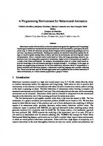
Fig. 1: Overview of the software architecture of SwarmSimX. The rest of the paper is organized as follows: Sect. 2 illustrates the design principles and software architecture behind the inner workings of SwarmSimX, Sect. 3 reports the results of experiments aimed at validating the realism and real-time capabilities of the simulation software, and Sect. 4 draws concluding remarks and discusses future directions. A copy of SwarmSimX can be downloaded from the subversion repository at https://svn.kyb.mpg.de/kyb-robotics. Additional media can be found in the video section at http://laechele.eu/SwarmSimX/.
2
Software Architecture
The SSX simulation environment can be divided into three main parts: the visual representation; the physical representation; and Artifacts. Figure 1 gives an overview of the elements used in the simulation and how they are related among themselves. In the nomenclature of SSX, the visual representation is managed by the RenderEngine with individual elements being represented by RenderNodes. Symmetrically, the physical representation is managed by the PhysicEngine and the individual parts are called PhysicNodes. Both, Physic- and RenderNodes can be connected to form tree structures. Child nodes are defined w.r.t. the parent node to which they are associated, and may contain information about the position, orientation, mass, and similar quantities. Because of the abstract nature of the RenderEngine and PhysicEngine the whole software framework is not affected by a particular implementation using some specific Render Library or Physics Library. The visual and physical representations are related to each other, as the physical representation is used to perform the actual simulation and the visual representation displays the behaviour of the objects being simulated. This relationship is expressed in the parallel structure of the design layout. At every Preprint version
3
3rd SIMPAR (2012)
timestep of the simulation, the execution of logical modules (namely Drivers and Sensors) is triggered. These modules can perform any kind of computation and are used to extend the simulation with custom logic or functionalities. Drivers implement the behaviour of objects within the simulation environment. A Driver can represent the control program of an Unmanned Aerial Vehicle (UAV) that applies the appropriate input forces and torques to the physical object in order to attain the desired angles received by an external navigation algorithm. Another example is the logical module of an automated door that opens whenever an object moves within a certain range and closes after a given period of time with no new sensor input. Sensors are used whenever information concerning the simulated environment or the simulator variables needs to be retrieved, e.g., in order to emulate the measurements of a real transducer or to obtain the current simulation time. For example, this allows an easy porting of a control algorithm implemented for real hardware to the simulation by properly emulating all the needed sensory inputs. One can also conceive virtual sensors able to measure the global state of the simulated environment. These are not meant to represent real sensor units, but rather to provide a helpful tool while developing and debugging new algorithms. All these parts are stored together into a single object called Artifact. Artifacts state the main concept of SwarmSimX. Everything that can be placed in the simulation environment is represented as an Artifact. An Artifact may contain multiple or no references to RenderNodes and PhysicNodes. Also, Sensors and Drivers are not mandatory. 2.1
Main execution loop
The execution of the simulation timesteps is solely the responsibility of the Environment. At the beginning of a timestep, the update of the PhysicEngine gets triggered. After this event, the Drivers and Sensors of the simulation get the chance to perform their computation. This particular step exploits the parallel computing power of modern CPUs by triggering the execution of a separate thread associated with each Artifact which contains at least one Sensor or Driver. The workload of computations posed by user code is spread among the CPUs of the system, hence increasing the performance. The execution of the threads needs to be synchronized with the triggering of the simulation timestep, meaning that the Environment waits until the calculation of all threads is complete before proceeding. Finally, the remaining time until the next timestep is due is calculated as tw = td − tn , with td being the desired simulation time, i.e., the number of simulation timesteps N times the timestep τ , and tn the current wall-clock-time (WCT). The execution of the simulation is stopped for tw using precise wait methods, if and only if tw is positive, otherwise the next step is triggered immediately. In this case a warning message is issued stating the break of the RT-constraint. It is important to note that the aforementioned wait step is most significant for the RT-capabilities of SSX. Several different libraries support precise methods for waiting and a previously conducted experiment showed the best results when utilizing the boost [12] library. Note also that, in the case of an offset Preprint version
4
3rd SIMPAR (2012)
between simulation time and WCT, this triggering paradigm will recover this error assuming the execution time of subsequent timesteps is smaller than τ . 2.2
Extending the simulation
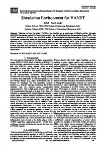
The goal of being able to create custom robots with sensors attached and program logic demands that the custom parts are independent from the simulation environment. Recompiling the whole simulation environment after adding new robots is time consuming and redundant. Even worse, exchanging projects between different users may prove difficult, as the code is tightly coupled to a certain simulation environment. SwarmSimX provides the possibility to load program code of Drivers and Sensors at runtime. In both cases an abstract interface defines methods for creating, configuring, running and destroying the class representing the program logic. Drivers are always associated with an Artifact and only one Driver per Artifact may be defined. Sensors are also associated with an Artifact but, in contrast to the Driver, multiple Sensors per Artifact may be created. Drivers, Sensors, and SimulationExtensions are loaded dynamically, i.e., at runtime, exploiting the features of the system libraries. The C language provides an easy to use library for loading and calling external libraries dynamically, called dlopen. For this, two functions are defined in a extern "C" {}-block that are responsible for creating and destroying the concrete class. The class itself derives from the Driver, Sensor or SimulationExtension abstract class that define a set of virtual methods. Driver The interface definition of the Driver is very slim compared to other classes. Methods for configuring the Driver using a Descriptor, setting the associated Artifact and Environment, and calculating a simulation step are provided. In addition to the interface definition, two functions need to be implemented for every Driver. As mentioned before, these two functions are necessary to dynamically load libraries and create instances of any Driver implemented by the user. Artifacts are responsible for creating their Driver defined by the Artifact XML file. Figure 2 shows the interaction involved in creating a Driver. First an Artifact requests a Driver instance given the name. Then the ClassLoader loads the library and calls the create-method. If all these steps were successful, the ClassLoader returns an instance of the specified Driver. In a final step the Artifact registers itself to the Driver and triggers the configuration. The ClassLoader is responsible for freeing all Driver instances created during the lifecycle of the simulation and is done when the simulation environment gets shut down by the user. This ensures that no method call will reach an already freed Driver, resulting in a segmentation error. Sensor Sensors provide information about the simulation environment. Utilizing features of the Environment, Sensors can access both engines and gain access to all created Artifacts of the simulation. All possible information is therefore available to the Sensor. Information provided by the Sensor is distributed to all registered SensorCallBacks. This implementation follows the Observer Pattern [13], which allows for distributing information without the need of polling for data. In this case the Sensor itself is responsible for triggering the update process. Loading Sensors at runtime follows the same paradigm as loading Drivers. Preprint version
5
3rd SIMPAR (2012)
Fig. 2: Interaction involved when creating a ConcreteDriver that implements the Driver interface and the create, destroy functions both defined in an extern "C" {}-block. All Sensors are associated with the corresponding Artifact, but the Driver is responsible for registering SensorCallbacks. This responsibility can either be implemented in a separate class, which handles the Sensor output or within the Driver itself. As described earlier, Drivers have access to the Environment and therefore access to all Artifacts created in the virtual environment. The Sensor class does not check affiliation of the registered SensorCallBack. Therefore it is possible to register a callback at a Sensor that is associated with a different Artifact. This allows for a very fast way of sharing information between different robots represented by Artifacts, because no data needs to be copied, serialized or transmitted to other robots. SimulationExtension Drivers and Sensors allow Artifacts to be extended in their functionality and they may also be reused within the context of the SSX framework. But true reusable software must not be limited to a certain framework or even programming language [14]. SimulationExtensions provide a very simple interface with methods for initialization and shutdown of the extension. Libraries may be loaded by these modules to form bridges to other software frameworks. This approach ensures the reusability of SSX as a simulation environment module that is part of a more complex Robotics Software System. The init methods of the extensions are called by the simulation before the actual configure and start steps of the Engines. The shutdown-method is called after all Engines have stopped their execution. This paradigm of “first in, last out” ensures that the extensions are always valid while the simulation is running. A common use-case of this feature is the connection of SSX with some kind of middleware that is interacting with the actual control program of the robot. A SimulationExtension providing ROS [15] support has been implemented and used for the experiments performed during this work. Drivers and Sensors may request a reference to the ROS extension at runtime from the Environment. The ROS extension stores a main ROS node and is responsible for managing an asynchronous spinner thread. Using the main ROS node, new topics may be published or callbacks may be registered to already existing topics. Preprint version
6
3rd SIMPAR (2012)
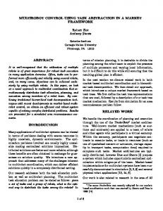
Fig. 3: Three screenshots taken from different simulations. Left: simulated quadrotor during the physical fidelity test. Center: stroboscopic sequence of a cooperative-aerial grasping performed by a quadrotor and a ground robot. Right: 70 quadrotors performing autonomous formation control on a spherical surface during the real-time capabilities vs. number of robots test.
3
Validation
Our simulation environment SSX has been successfully employed to validate several multi-robot control algorithms proposed in recent papers by some of the authors, see, e.g., [16–18] and http://www.youtube.com/user/MPIRobotics for the related video selection. In the majority of these works we also performed real-robot experiments using the same algorithms and we observed a remarkable similarity between simulative and experimental results. In addition, in these works we effectively used SSX in two challenging scenarios requiring real-time simulation: (1) simulation of robots interacting with one or more human operators by means of real haptic interfaces, and (2) simulation of several obstacle sensors providing virtual measurements to the controllers of real robots in order to simulate virtual obstacles in the real environment. We refer the reader to those works in order to appreciate the use of SSX in an applied robotics context where fidelity and real-time are of extreme importance. In addition to that, in this section we report two quantitative studies investigating the fulfillment of two cardinal requirements of any robotic simulator: the physical fidelity, and the real-time capabilities with multiple robots. For these tests we used a single Linux machine running Ubuntu[19] 12.04 R R Xeon with the generic Ubuntu Linux kernel 3.2.0. The machine has a Intel CPU W3520 (endowed with 8 cores – HyperThreading enabled), 12 GB of main R R memory and a NVIDIA GeForce 9800 GT GPU. The version of SwarmSimX R R PhysX [11] 3.2.0 and Ogre3D [20] used for all experiments utilizes NVIDIA 1.7.4 as the Physics Library and Render Library, respectively. The focus of this section is the validation of the quality of the physical simulation and the RT capabilities. Profound validations of the rendering performance of SSX in general and Ogre3D in particular have been omitted. For an impression of the quality of the rendering performed by Ogre3D we refer to Fig. 3 showing screenshots of different experiment scenarios. 3.1
Physical fidelity
The main purpose of a simulation environment is to test and analyze new algorithms in a safe and controlled environment before porting them to the real Preprint version
7
3rd SIMPAR (2012)
world case. The more the behavior of a simulated robot is comparable to that of its real counterpart, the better the chances that an algorithm working in simulation will work in reality with comparable results. This is depending almost solely on the degree of physical fidelity of the simulation environment being used. In order to test the physical fidelity of SSX we compared the tracking performances of a real and a virtual quadrotor flying two different eight-shaped trajectories, a vertical and a horizontal one, while maintaining a constant yaw velocity. The global position, orientation, linear and angular velocities of the real quadrotor have been recorded by means of an external motion capture system and used for the comparison. In order to minimize the effect of external factors in the comparison, we used exactly the same flight-controller code and control parameters (e.g., gains) both for the virtual and the real cases. In particular we implemented a standard cascaded controller composed by two nested control loops. The outer loop controls the position of the center of mass of the robot: it reads the current robot state (e.g., the robot position and velocity) and provides the appropriate orientation and thrust to the inner control loop in order to track the desired centroid trajectory. The inner loop lets the quadrotor achieve the appropriate orientation by acting on the propeller speeds, i.e., on the total torque of the aerial vehicle. Nevertheless, to simulate in real-time the extremely complex aerodynamics of all the propellers is practically unfeasible. Therefore we experimentally identified the non-linear map that relates the rotational speeds to the attained forces and torques. This allowed us to efficiently simulate the UAV dynamics by directly applying the forces and torques resulting from that map to the UAV body. For the sake of fidelity we also used in simulation the same code executing the inner loop on the real quadrotor. This is implemented using only integers, runs on a fixed-point microcontroller, and uses the measurements coming from an onboard Inertial Measurement Unit (IMU). For this purpose a virtual IMU has also been implemented to provide linear acceleration and angular velocity with noise characteristics similar to that of the IMU mounted on the real quadrotor. The cumulative distribution of the tracking error (in short: cumulative error ) is a valid tool to give an overall view of the tracking behavior of a robot following a desired trajectory. In order to define this function, consider a desired trajectory pd defined over a time interval [t0 , tf ] and the actual trajectory executed by the robot p in the same interval, the cumulative distribution function is defined as: Fp,pd ,[t0 ,tf ] (d) =
1 tf − t0
Z
tf
H(kpd (t) − p(t)k − d) dt,
t0
where d ≥ 0 represents a distance, and H : R → {0, 1} is the Heaviside (or unitstep) function, which returns 0 when its argument is negative and 1 otherwise. In other words the cumulative error returns, for every distance d, the percentage of time in which the actual trajectory p has been closer than d to pd . The faster F converges to 1 for increasing d the better is the tracking behavior of the controller. Nevertheless, here we are not interested in the absolute tracking performances of the two controllers but in the degree of similarity between the simulated and real behaviors. In fact, assuming the same software is controlling each quadrotor Preprint version
8
3rd SIMPAR (2012)
Horizontal Trajectory
1
Cumulative Error
Cumulative Error
0.9
0.8
0.8
0.7
0.7
0.6
0.6
0.5
0.5
0.4
0.4
0.3
0.3
0.2
0.2
0.1 00
Vertical Trajectory
1
0.9
0.1 0.05
0.1
0.15
0.2
0.25
00
0.3
0.05
0.1
Distance [m]
(a)
0.25
0.3
Vertical Trajectory
1
Cumulative Error
0.9
Cumulative Error
0.9 0.8
0.8
0.7
0.7
0.6
0.6
0.5
0.5
0.4
0.4
0.3
0.3
0.2
0.2
0.1 00
0.2
(b)
Horizontal Trajectory
1
0.15
Distance [m]
0.1 0.05
0.1
0.15
0.2
0.25
00
0.3
Distance [m]
0.05
0.1
0.15
0.2
0.25
0.3
Distance [m]
(c)
(d)
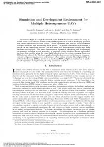
Fig. 4: Comparison between the cumulative distributions of the tracking errors. (a): Real quadrotor hori. traj. (mean: 0.0919 m, std: 0.0412 m); (b): Real quadrotor vert. traj.(mean: 0.0654 m, std: 0.0179 m); (c): Simulated quadrotor hori. traj. (mean: 0.1245 m, std: 0.0444 m); (d): Simulated quadrotor vert. traj. (mean: 0.0546 m, std: 0.0131 m) and using similar sensor values, a good simulator should show the same tracking behavior compared to the real case for the same desired trajectories. Only in this way testing a new controller in simulation can give a useful insight about the applicability of the proposed controller in reality. The results of our experimental test, showing the fidelity of our simulation, are reported in Fig. 4. Both in the case of horizontal (Figs. 4(a),(c)) and vertical (Figs. 4(b),(d)) trajectories it is possible to appreciate the similar shape of the cumulative-error plots between the simulated and the real cases. Note also that, as usual for the quadrotor, the vertical tracking performs much better than the horizontal one (in both the virtual and real case).
3.2
Real-time capabilities vs. number of robots
One feature of SSX is the capability to simulate dozens of 3D robots simultaneously in real-time. The possibility of obtain a real-time simulation depends mainly upon two factors: (1) the desired simulation time-step, i.e., the resolution of the physical integration, and (2) the size of “extra” computation that all the artifacts in the environment require at every time-step, e.g., measurement acquisition, estimation/control computation, inter-robot communication. Clearly, Preprint version
9
3rd SIMPAR (2012)
Calculation time [s]
Calculation time vs. number of robots
0.04 0.03 0.02 0.01 0 1
10
20
30
40
50
60
70
Number of quadrotors N
80
90
100
Fig. 5: Box-plots of the time needed for calculating a single timestep of SSX as a function of the number of quadrotors being simulated. Red crosses, red horizontal lines, blue boxes, and black whiskers represent outliers, median values, percentile margins, and max-min values (without outliers), respectively. The simulation timestep (τ = 0.02 s) is denoted with a green dashed line. the influence of the second factor increases as the number of robots increases.3 For users interested in real-time multi-robot applications, a basic information is given by how many robots can be simulated with a given physical accuracy (simulation time-step) and a given multi-robot coordination algorithm (comprising sensors, estimators, control, and communication). Therefore we conducted a Monte Carlo study to evaluate how the execution time of a whole simulation step is influenced by the number of simulated robots in SSX. As reference scenario we considered a group of quadrotors implementing a standard formation-control plus obstacle-avoidance algorithm based on artificial potentials. Like in the previous experimental test, every quadrotor runs a flight controller able to command the torques generated by every propeller in order to stabilize the flight. In addition to that, in this test every robot runs the coordination/avoidance algorithm and a range sensor simulator to retrieve the relative position of other robots and objects within its neighboring environment. Fig. 5 depicts our results of the comparison of the real-time capabilities of SSX and the number of robots included in the simulation. In total 11 different cases have been tested, each with a different number of robots being simulated simultaneously for a total of about 5 thousand samples of the simulation time per case. In all cases the simulation timestep was set to 0.02 s, i.e. 50 Hz, denoted with a green dashed line in Fig. 5. For each case a boxplot displays the median, 25th and 75th percentiles, and max/min values (using whiskers) of the computation time after removing extreme data points considered outliers (also plotted in the figure). The median lines, percentile boxes, and whiskers stay compact in almost all the cases, showing a very small variance in the computational time needed 3
The influence of the number of robots on the first factor is almost negligible for R R NVIDIA PhysX used by SwarmSimX, up to a few thousands of rigid bodies.
Preprint version
10
3rd SIMPAR (2012)
to calculate a timestep. This behavior is essential for the RT reliability of the simulation. Note also, that the median calculation time increases almost linearly with the number of robots, resulting from the distributed formation control of the group of quadrotors. SwarmSimX was able to hold the RT-constraint of the timestep in almost all cases except the case with 100 quadrotors. Notice that in this case the median and percentile box is above the 0.02 s mark, resulting in a growing error offset between simulation and wall-clock time. Although the RT-constraints will always be broken in this case the simulation still produces valid results useful for offline simulation of algorithms, e.g., formation control, sensor fusion, etc.
4
Conclusion and Future Work
In this paper we have presented a novel simulation environment, called SwarmSimX (SSX), tailored for the real-time simulation of multiple robots acting within a 3D physical environment. The software architecture is designed to encapsulate the main parts, namely RenderEngine, PhysicEngine, and Architect, so as to ensure independence from the underlying libraries used for simulation. Exploiting the features of the dlopen library, new robots and sensors can be added to the simulation environment without the need of recompiling SSX itself. In addition Simulation extensions may be used to directly extend the features of the simulation, e.g., to provide an easy interface to other middleware (ROS) or other external software packages. Aside from the description of the internal design, we also performed several tests aimed at validating the physical fidelity and real-time capabilities of SSX. In particular, we showed that the tracking performance of a virtual quadrotor following a predefined trajectory can be compared to the flight behavior of a real quadrotor following the same trajectory. These results show a very good performance in terms of representing the actual flight behavior of a single UAV, and in running the simulating environment in real-time. With an acceptable time-step of 0.02 s SSX can simulate dozens (at least 90) quadrotors with their associated sensors/controllers simultaneously. Currently SwarmSimX is designed to simulate rigid-body dynamics only, but future works may focus on the inclusion of additional concepts provided by modern physics engines, e.g., joints, vehicle models, cloths, fluids. A redesign of the software architecture to allow an online exchange of the implementation of the main modules, e.g., RenderEngine, could increase even more the independence from specific implementations.
Acknowledgements The authors like to thank Martin Riedel for his valuable work on the middleware software design used for the control programs. This research was partly supported by WCU (World Class University) program funded by the Ministry of Education, Science and Technology through the National Research Foundation of Korea (R31-10008). Preprint version
11
3rd SIMPAR (2012)
References 1. Pinciroli, C., Trianni, V., O’Grady, R., Pini, G., Brutschy, a., Brambilla, M., Mathews, N., Ferrante, E., Di Caro, G., Ducatelle, F., Stirling, T., Gutierrez, a., Gambardella, L.M., Dorigo, M.: ARGoS: A modular, multi-engine simulator for heterogeneous swarm robotics. 2011 IEEE/RSJ International Conference on Intelligent Robots and Systems (September 2011) 5027–5034 2. Craighead, J., Murphy, R., Burke, J., Goldiez, B.: A survey of commercial & open source unmanned vehicle simulators. In: Proc. IEEE Int Robotics and Automation Conf. (April 2007) 852–857 3. Alex, A.L., Bruny, T., Sidman, J., Weil, S.A., Inc, A., Ma, W.: From gaming to training: A review of studies on fidelity, immersion, presence, and buy-in and their effects on transfer in PC-based simulations and games (November 2005) 4. Boeing, A., Br¨ aunl, T.: Evaluation of real-time physics simulation systems. In: Proceedings of the 5th international conference on Computer graphics and interactive techniques in Australia and Southeast Asia. GRAPHITE ’07, New York, NY, USA, ACM (2007) 281–288 5. Diankov, R.: Automated Construction of Robotic Manipulation Programs. PhD thesis, Carnegie Mellon University, Robotics Institute (August 2010) 6. Echeverria, G., Lassabe, N., Degroote, A., Lemaignan, S.: Modular openrobots simulation engine: Morse. In: Proceedings of the IEEE ICRA. (2011) 7. Blender Foundation: Blender. http://www.blender.org/ (Accessed August 2012) 8. Freese, M., Singh, S., Ozaki, F., Matsuhira, N.: Virtual Robot Experimentation Platform V-REP: A Versatile 3D Robot Simulator. In: Simulation Modeling and Programming for Autonomous Robots. Volume 6472 of Lecture Notes in Computer Science. Springer Berlin Heidelberg (2010) 51–62 9. Michel, O.: Cyberbotics Ltd. Webots TM : Professional Mobile Robot Simulation. International Journal of Advanced Robotic Systems 1 (2004) 39–42 10. Koenig, N., Howard, A.: Design and use paradigms for gazebo, an open-source multi-robot simulator. 2004 IEEERSJ International Conference on Intelligent Robots and Systems IROS IEEE Cat No04CH37566 3 (2004) 2149–2154 R R 11. NVIDIA : PhysX . http://www.geforce.com/hardware/technology/physx (Accessed May 2012) 12. boost: boost C++ libraries. http://www.boost.org/ (Accessed May 2012) 13. Gamma, E., Helm, R., Johnson, R., Vlissides, J.: Design Patterns: Elements of Reusable Object-Oriented Software. first edn. Addison-Wesley Professional (November 1994) 14. Biggs, G., Makarenko, A., Brooks, A., Kaupp, T., Moser, M.: Gearbox: Truly reusable robot software (poster). In: Proc. IEEE/RSJ Int. Conference on Intelligent Robots and Systems, Nice, France (September 2008) 15. ROS.org community: ROS Wiki. http://www.ros.org (Accessed May 2012) 16. Franchi, A., Secchi, C., Son, H.I., B¨ ulthoff, H.H., Robuffo Giordano, P.: Bilateral teleoperation of groups of mobile robots with time-varying topology. Accepted to IEEE Trans. on Robotics (2012) 17. Franchi, A., Secchi, C., Ryll, M., B¨ ulthoff, H.H., Robuffo Giordano, P.: Bilateral shared control of multiple quadrotors: Balancing autonomy and human assistance with a group of UAVs. Conditionally Accepted to IEEE Robotics & Automation Magazine (2012) 18. Robuffo Giordano, P., Franchi, A., Secchi, C., B¨ ulthoff, H.H.: Passivity-based decentralized connectivity maintenance in the bilateral teleoperation of multiple UAVs. In: 2011 Robotics: Science and Systems, Los Angeles, CA (Jun. 2011) 19. Canonical Ltd: Ubuntu. http://www.ubuntu.com (Accessed October 2012) 20. Torus Knot Software Ltd: Ogre3D. http://www.ogre3d.org/ (Accessed May 2012)
Preprint version
12
3rd SIMPAR (2012)