International Journal of Electrical and Computer Engineering (IJECE) Vol. 6, No. 2, April 2016, pp. 474~483 ISSN: 2088-8708, DOI: 10.11591/ijece.v6i2.9146
474
Switching FOC Method for Vector Control of Single-Phase Induction Motor Drives Mohammad Jannati*, Nik Rumzi Nik Idris*, Mohd Junaidi Abdul Aziz*, Tole Sutikno**, M. Ghanbari*** * UTM-PROTON Future Drive Laboratory, Faculty of Electrical Engineering, Universiti Teknologi Malaysia, 81310 Skudai, Johor Bahru, Malaysia ** Department of Electrical Engineering, Faculty of Industrial Technology, Universitas Ahmad Dahlan, Yogyakarta 55164, Indonesia *** Department of Electrical Engineering, Aliabad Katoul Branch, Islamic Azad University, Aliabad Katoul, Iran
Article Info
ABSTRACT
Article history:
This paper proposes a novel vector control method based on Rotor flux Field-Oriented Control (RFOC) for single-phase Induction Motor (IM) drives. It is shown that in a rotating reference frame, the single-phase IM equations can be separated into forward and backward equations with balanced structures. In order to accommodate for these forward and backward equations, a drive system consisting of two RFOCs that are switched interchangeably, is proposed. Alternatively, these two RFOC algorithms can be simplified as a single FOC algorithm. The analysis, controller design and simulation of the proposed technique showed that it is feasible for single-phase IM drive for high performance applications.
Received Oct 10, 2015 Revised Dec 28, 2015 Accepted Jan 12, 2016 Keyword: AC Drives High performance applications Single-phase induction motor Switching FOC Vector control
Copyright © 2016 Institute of Advanced Engineering and Science. All rights reserved.
Corresponding Author: Mohammad Jannati, UTM-PROTON Future Drive Laboratory, Faculty of Electrical Engineering, Universiti Teknologi Malaysia, 81310 Skudai, Johor Bahru, Malaysia. Email:
[email protected]
1.
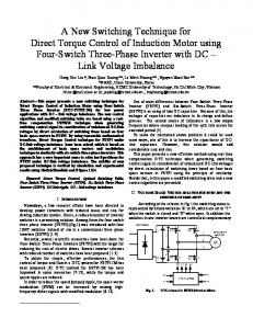
INTRODUCTION Single-phase Induction Motor (IM) is one of the most applicable electrical machines which are used in low power domestic and industrial applications. This electrical motor can be used in vacuum cleaners, washers, compressors, fans and etc. Generally, a single-phase IM has two main and auxiliary windings and its operation needs one or two capacitors. To guarantee the efficient use of energy, the investigation of different single-phase IM drive schemes have been increased by researchers. In these drives the single-phase IM, without capacitor, is treated as an asymmetric 2-phase IM [1]. Different converter topologies have been proposed to supply single-phase machine, for example, one-leg inverter [2], 2-leg inverter [1], [3] 3-leg inverter [4], [5] and 4-leg inverter [6]. This paper investigates the use of 2-leg inverter as shown in Figure 1 for feeding the single-phase IM. This configuration is indicated for high performance applications [1], [3] (It should be pointed out that the focus given here is on the detailed analysis and design of the vector control strategy for single-phase IM drives). Field-Oriented Control (FOC) method is widely used for implementing high performance vector control of single-phase IM drives. This method has been increasingly adopted as the standard control technique for industrial demands [1], [3], [7]-[16]. One of the main drawbacks in the presented FOC methods to control single-phase IM drives is using the supposition of (Md/Mq)2=Lds/Lqs (Lds, Lqs, Md, Mq indicate the stator and rotor d-q axes self and mutual Journal homepage: http://iaesjournal.com/online/index.php/IJECE
475
ISSN: 2088-8708
inductances) [1], [3], [7]-[15]. It can be noted that for simplifying vector control equations in single-phase IM the supposition of (Md/Mq)2=Lds/Lqs is used. It was shown in [16] using this assumption is reflected in the torque response of the single-phase IM drive system. In [16], a method for Indirect Rotor flux FOC (IRFOC) of single-phase IM without using (Md/Mq)2=Lds/Lqs has been presented. However, the introduced method in [16] is extremely depends on motor parameters variations. This study shows the single-phase IM can be modeled as two balanced circuits (forward and backward circuits). Based on this simplifying, a novel vector control method for single-phase IM based on FOC algorithm and without using (Md/Mq)2=Lds/Lqs is presented (switching FOC). This paper is organized as follows: After introduction in section 1, in section 2, d-q model of single-phase IM is presented. Next, section 3 describes the development of the FOC algorithm, followed by presenting proposed switching FOC scheme for vector control of single-phase IM drives. The performance of the presented method is analyzed and checked using Matlab/Simulink software in section 4 and section 5 concludes the paper.
Figure 1. Single-phase IM drive system (2-leg inverter)
2.
MODELING OF SINGLE-PHASE IM Neglecting the core saturation, the d-q model of the single-phase IM in the stationary reference frame (superscript “s”) can be shown as the following equations [15]:
(1)
In (1), vsds, vsqs are the stator d-q axes voltages, isds, isqs are the stator d-q axes currents, isdr, isqr are the rotor d-q axes currents, λsds, λsqs are the stator d-q axes fluxes and λsdr, λsqr are the rotor d-q axes fluxes. rds, rqs, rr indicate the stator and rotor d-q axes resistances. Lds, Lqs, Lr, Md, Mq denote the stator and rotor d-q axes self and mutual inductances. r is the motor speed. τe, τl are electromagnetic torque and load torque. J, F are the moment of inertia and viscous friction coefficient respectively.
3.
SWITCHING FOC METHOD FOR VECTOR CONTROL OF SINGLE-PHASE IM In this section, a novel method for vector control of single-phase IM drives based on IRFOC is proposed. In the RFOC strategy it is necessary that the machine equations transfer to the rotating reference IJECE Vol. 6, No. 2, April 2016 : 474 – 483
IJECE
ISSN: 2088-8708
476
frame. For this purpose, the transformation matrix as shown in equation (2) is applied to the machine equations [17]:
T cos sin e s
e
e
sin e cos e
(2)
In (2), superscript “e” indicates that the equations are in the rotating reference frame. Moreover, “θe” is the angle between the stationary and rotating reference frames. By applying (2) to the equations of the single-phase IM (equations (1)), equations (3a) and (3b) are obtained:
Lds Lqs M d M q d M d M q rds rqs Lds Lqs d e e 2 2 2 2 2 dt dt e vdse M d M q M d M q d ids Lds Lqs rds rqs Lds Lqs d e e e e 2 2 2 2 2 dt iqs dt vqs i e M d M q d M d M q r L d 0 e r e r Lr dre r r 2 2 dt dt 0 iqr M d M q d d M d M q e r Lr rr Lr e r 2 2 dt dt e vds e vqs ve dr e vqr
L Lqs M d M q d M d M q rds rqs Lds Lqs d e ds e 2 2 2 2 2 dt dt idse M M M M L L r r L L d d ds qs ds qs ds qs d q d q e e e 2 2 2 2 2 dt iqs dt idre M d M q d M M q e r d 0 0 e 2 2 dt iqr Md Mq d M d M q 0 0 e r 2 2 dt
(3a)
e vds e vqs v e dr e vqr
idse cos e sin e 0 0 e 0 0 iqs sin e cos e idse cos e sin e 0 0 idss e cos e 0 0 iqss iqs sine i e 0 0 cos e sin e idrs dr e 0 sin e cos e iqrs iqr 0 i e 0 0 cos e sin e dr e iqr 0 0 sin e cos e
(3b)
In (3a), “ωe” is the angular velocity of the rotor field oriented reference frame. As can be seen, in general, equation (3a) includes two terms (forward term: superscript “+e” and backward term: superscript “e”). Each term represents a balanced equation where rotates in the forward or backward direction as shown in Figure 2.
Switching FOC Method for Vector Control of Single-Phase Induction Motor Drives (M. Jannati)
477
ISSN: 2088-8708
Figure 2. Forward, backward and stationary reference frames (“+e”: forward, “-e”: backward and “s”: stationary) As can be seen from (3a), the structure of the forward and backward terms is similar to the conventional 3-phase IM equations. The only difference between forward terms and conventional 3-phase IM equations is that, in the forward terms there are: (rds+rqs)/2, (Lds+Lqs)/2 and (Md+Mq)/2 but in the conventional 3-phase IM we have: rs, Ls=Lls+1.5Lms and M=1.5Lms. Moreover, the difference between backward terms and conventional 3-phase IM equations is that, in the backward terms there are: (rds-rqs)/2, (Lds-Lqs)/2, (Md-Mq)/2, rr=0, Lr=0 and there are -iqse and -iqre but in the conventional 3-phase IM we have: Ls=Lls+1.5Lms, M=1.5Lms, rr≠0, Lr≠0 and there are iqse and iqre. The block diagram of forward and backward IRFOC can be shown as Figure 3 and Figure 4 respectively.
Figure 3. Block diagram of forward IRFOC
IJECE Vol. 6, No. 2, April 2016 : 474 – 483
IJECE
ISSN: 2088-8708
478
Figure 4. Block diagram of backward IRFOC Therefore, two developed IRFOC algorithms with two forward and backward currents can be used for vector control of a single-phase IM. The block diagram of the proposed IRFOC for single-phase IM drives is shown in Figure 5. In Figure 5, in order to alternately switched between the forward and backward states, a switch is used whereby this switch will consecutively change positions in each sampling time.
Figure 5. Block diagram of the proposed IRFOC for vector control of single-phase IM drives In Figure 5, 2 to 2 transformation matrix ([Ts]) is obtained as (4):
Ts
1 0 0 1
(4)
Switching FOC Method for Vector Control of Single-Phase Induction Motor Drives (M. Jannati)
479
ISSN: 2088-8708
Consequently, to simplify proposed FOC in Figure 5, single FOC algorithm with only changes in the motor parameters can be used for vector control of single-phase IM drives (see Figure 6).
Figure 6. Block diagram of the simplified proposed FOC for vector control of single-phase IM drives
4.
SIMULATION RESULTS In this section, the simulation results based on Figure 5 and Figure 6 is carried out to validate the proposed control strategy. A 0.25Hp single-phase IM is driven by a 2-leg voltage source inverter. The simulation investigation is mainly focused on the motor speed and torque responses. The motor parameters are shown in Table 1. Table 1. Ratings and parameters of the single-phase IM Voltage Frequency (f) No. of Poles Power rds ras Ma rr Lds Las J F
90V 60Hz 4 0.25Hp 7.14 2.02 0.1772H 4.12 0.1885H 0.1844H 0.0146kg.m2 0.0N.m.s
Figure 7 shows the simulation results of the proposed controller for a trapezoidal reference speed from 500 rpm to -500 rpm. It is seen that the real speed signal are so accurate that hardly can be distinguished from the corresponding reference speed signal. As can be seen from Figure 7, the maximum speed error is about 1.5 rpm. The main and auxiliary stator currents and electromagnetic torque for trapezoidal reference speed are also shown in Figure 7. As shown from Figure 7, the sinusoidal form of the stator currents is maintained in the different speed. Moreover, it can be seen that the electromagnetic torque has a quick response with no pulsations.
IJECE Vol. 6, No. 2, April 2016 : 474 – 483
IJECE
ISSN: 2088-8708
480
Figure 7. Simulation results of the proposed controller for the trapezoidal reference speed from top to bottom: Stator Currents, Zoom of Stator Currents, Speed, Speed Error, Torque
Switching FOC Method for Vector Control of Single-Phase Induction Motor Drives (M. Jannati)
481
ISSN: 2088-8708
Figure 8 shows simulation results of the proposed strategy for vector control of the single-phase IM in the nominal and zero reference speeds and under load condition. In Figure 8, the motor is running at the reference speed of 0rpm. Then at t=3s a step change of 1800rpm is introduced. In addition, at t=9s, a step load of 1.2N.m is introduced and at t=11s is removed. It is evident from Figure 8 that although at the moment of applying load there is a small speed dip but then it is restored quickly. Based on presented results in Figure 8, using proposed drive system, the maximum speed error in nominal speed and during load condition is about 0.4 rpm. Moreover, the maximum speed error in zero reference speed is about 0.1 rpm. As shown from Figure 8 the torque increases accordingly to ensure that the speed is maintained at 1800rpm. It can be seen from Figure 7 and Figure 8 that the dynamic performance of the proposed controller for the single-phase IM is extremely acceptable.
Figure 8. Simulation results of the proposed controller in the nominal and zero reference speeds and under load condition from top to bottom: Speed, Torque IJECE Vol. 6, No. 2, April 2016 : 474 – 483
IJECE
ISSN: 2088-8708
482
Figure 9 shows the comparison between the steady-state torque response of the RFOC at the nominal reference speed by considering (Md/Mq)2=Lds/Lqs (e.g., [1], [3], [7]-[15]) and without considering (Md/Mq)2=Lds/Lqs (switching FOC). Larger torque ripple can be seen when the assumption (Md/Mq)2=Lds/Lqs is used. It is concluded in comparison with the previous schemes for RFOC of single-phase IM drives, the proposed controller in this study gives better performance.
Figure 9. Simulation results of the comparison between torque response at the nominal reference speed; left: assuming (Md/Mq)2=Lds/Lqs, right: not assuming (Md/Mq)2=Lds/Lqs. 5.
CONCLUSION In this paper, a vector control strategy for single-phase IM drives based on Indirect Rotor flux FieldOriented Control is proposed and tested. It was shown that the single-phase IM equations in the rotating reference frame can be classified as the balanced equations. Based on this simplicity, a novel vector control method using two developed IRFOC algorithms was proposed. As a result, these two algorithms were simplified as single IRFOC algorithm. Simulation results showed that the proposed switching FOC strategy works well over most speed ranges and under load condition.
REFERENCES [1] [2] [3] [4] [5] [6] [7] [8] [9] [10] [11] [12] [13] [14]
M.R. Correa, et al., "Rotor-flux-oriented control of a single-phase induction motor drive", IEEE Transactions on Industrial Electronics, vol. 47, pp. 832-841, Aug. 2000. M. Chomat and T.A. Lipo, "Adjustable-speed single-phase IM drive with reduced number of switches", IEEE Transaction on Industrial Applications, vol. 39, pp. 819-825, May/Jun. 2003. M.B. de Rossiter Corrêa, et al., "Vector control strategies for single-phase induction motor drive systems", IEEE Transactions on Industrial Electronics, vol. 51, pp. 1073-1080, 2004. M.A. Jabbar, et al., "Space-vector modulation in a two-phase induction motor drive for constant-power operation", IEEE Transactions on Industrial Electronics, vol. 51, pp. 1081-1088, 2004. M. Guerreiro, et al., "A Speed Controller for a Two-Winding Induction Motor Based on Diametrical Inversion", IEEE Transaction on Industrial Applications, vol. 57, pp. 449-456, 2010. C. Young, et al., "New Inverter-Driven Design and Control Method for Two-Phase Induction Motor Drives", IEE Proceedings on Electric Power Application, vol. 143, pp. 458-466, 1996. S. Reicy and S. Vaez-Zadeh, "Vector control of single-phase induction machine with maximum torque operation", In Proceedings of the IEEE International Symposium on Industrial Electronics, ISIE 2005, pp. 923-928, 2005. M. Jemli, et al., "Real-time implementation of IRFOC for single-phase induction motor drive using dSpace DS 1104 control board", Simulation Modelling Practice and Theory, vol. 17, pp. 1071-1080, 2009. H.B. Azza, et al., "High performance sensorless speed vector control of SPIM Drives with on-line stator resistance estimation", J. Simulat. Practice Theory, vol. 19, pp. 271-282, 2011. H. Ben Azza, et al., "Full-Digital Implementation of ISFOC for Single-Phase Induction Motor Drive Using dSpace DS 1104 Control Board", International Review of Electrical Engineering, vol. 3, pp. 721-729, 2008. H.B. Azza, et al., "Implementation of Sensorlee Speed Control for Two-Phase Induction Motor Drive Using ISFOC Strategy", Transactions of Electrical Engineering, vol. 35, pp. 63-74, Jun. 2011. M. Jannati, et al., "Speed Sensorless Direct Rotor Field-Oriented Control of Single-Phase Induction Motor Using Extended Kalman Filter", International Journal of Power Electronics and Drive Systems (IJPEDS), vol. 4, pp. 430438, 2014. M. Jannati and E. Fallah, "A new method for speed sensorless vector control of single-phase induction motor using Extended Kalman Filter", In 19th Iranian Conference on Electrical Engineering (ICEE), pp. 1-5, 2011. M. Jannati, et al., "A new method for RFOC of single-phase induction motor based on rotational transformations", In 2013 IEEE Student Conference on Research and Development (SCOReD), pp. 215-220, 2013.
Switching FOC Method for Vector Control of Single-Phase Induction Motor Drives (M. Jannati)
483
ISSN: 2088-8708
[15] D.H. Jang, "Problems Incurred in a Vector-Controlled Single-Phase Induction Motor, and a Proposal for a VectorControlled Two-Phase Induction Motor as a Replacement", IEEE Transaction on Power Electronics, vol. 28, pp. 526-536, Jan. 2013. [16] M. Jannati, et al., "An Exact Model for Rotor Field-Oriented Control of Single-Phase Induction Motors", TELKOMNIKA Indonesian Journal of Electrical Engineering, vol. 12, pp. 5110-5120, 2014. [17] P. Vas, "Vector Control of AC Machines", Oxford science publication, 1990.
IJECE Vol. 6, No. 2, April 2016 : 474 – 483