should be a CDN condition added to the Agent Term instance in the cor- ..... D. Amyot: Specification and Validation of Telecommunications Systems with Use.
Synthesizing SDL from Use Case Maps: An Experiment Yong He, Daniel Amyot, and Alan Williams School of Information Technology and Engineering University of Ottawa Ottawa, ON K1N 6N5, Canada {yonghe|damyot|awilliam}@site.uottawa.ca
Abstract. The Use Case Map (UCM) notation is part of the User Requirements Notation (URN), the most recent addition to ITU-T’s family of languages. UCM models describe functional requirements and highlevel designs with causal scenarios, superimposed on structures of components. It has been shown that UCMs can be transformed into more detailed MSC scenarios. However, UCMs are not executable as such. Early validation and exploration of requirements could benefit from a transformation to a formal, executable language. This paper presents the results of an experiment combining existing tool-supported techniques for the generation of MSCs from UCMs and for the synthesis of SDL from MSCs. In particular, this experiment provides useful results on the current interworking of such techniques and on requirements for future generations of tools. Through a simple case study, this paper also highlights questions and partial answers on the complementariness of these languages, on the usefulness of the resulting SDL models, and on potential improvements on the approach and on the languages themselves.
1
Introduction
Generating designs and implementations automatically from requirements is an old dream of many system developers. However, for particular types of systems, notations, and purposes, this dream may be very close to becoming reality. This paper explores the potential for automated generation of SDL models from Use Case Map (UCM) requirements scenarios in the context of early validation of distributed systems. The Use Case Map notation is one of the latest additions to the ITU-T family of languages. It is being standardized as a scenario notation part of the User Requirements Notation in the Z.150 series [2, 11]. UCM graphical models describe functional requirements and high-level designs with causal scenarios, superimposed on structures of components [5, 12]. UCMs are suitable for many requirements engineering activities and for dealing with abstract and intuitive representations of complex distributed systems. SDL is a well-established specification and design language that enables the execution and formal validation of models described as communicating state machines [9]. One of our goals is to combine the strengths of both languages.
2
Yong He et al.
In the scenario-driven development of distributed systems and services, it is important to leverage the investment in scenarios in order to generate systems rapidly, at low cost, and with a high quality. Constructing state-based behavioral models from scenarios that span multiple components is beneficial because this helps developers move from requirements to design in a systematic way. Such construction, whether analytic (i.e. manual, build-and-test approach) or synthetic (i.e. partially or fully automated), however raises many issues similar to those observed in the protocol engineering community [19]. The level of completeness, consistency, and formality of the source scenarios will influence what type of technique will be more suitable, e.g., analytic approaches are often more tolerant about the quality of the scenarios than synthetic approaches. On the other hand, synthetic approaches offer fast and deterministic transformations that are “correct” according to properties ensured by their construction algorithm, at the cost of less flexibility (e.g. non-functional requirements such as maintainability can hardly be considered during the conversion). In the past ten years, many scenario-based construction techniques have been proposed (a recent survey of which is available in [3]). Most start from a scenario language that specifies component communication, such as Message Sequence Charts (MSCs) [10] or UML sequence diagrams [18]. The automated construction of design models from more abstract scenario notations such as UCMs or UML activity diagrams proved to be more challenging because communication detail is not explicit and must be inferred during the construction. This paper does not introduce a new synthesis technique based on UCMs. Rather, it reports on experiments that combine existing work on the generation of MSCs from UCMs, and on the synthesis of SDL models from MSCs. Both parts are automated, and together they provide a continuous transition from requirements to design. For instance, the second release of the UCM Navigator tool (UCMNav 2, [17]) provides MSC generation capabilities while Telelogic Tau 4.4 integrates KLOCwork’s MSC2SDL synthesizer [14, 16]. Results from a case study (simple telephone system) will help us illustrate several problems faced during UCM→MSC→SDL transformations, in terms of existing practices and tool interworking. Section 2 first describes our source UCM specification, which contains a number of scenario definitions. The latter are used to produce individual MSCs (Section 3), which can be combined in various ways with a High-Level MSC (HMSC). Section 4 presents SDL models synthesized from these (H)MSCs. Several strategies aiming to solve language and tool interworking problems are explored along the way. Our main observations and recommendations regarding several concrete and important questions are found in Section 5, followed by related work and conclusions.
2
Source Use Case Map Model
The following UCM model describes the connection request phase in an agentbased telephony system with user-subscribed features. It was selected for this experiment because it covers most path constructs in the UCM notation, and
Lecture Notes in Computer Science
3
because it already contained a set of scenario definitions covering all the paths (see [17]). 2.1
Simple Telephony System
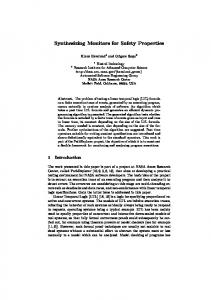
The root map in Fig. 1 gives an overview of the requirement scenarios that our system must support. Upon the request of an originating user (req), the originating agent will select the appropriate user feature (in stub Sorig) which could result in some feedback (notify). This may also cause the terminating agent to select another feature (in stub Sterm) which in turn can cause a number of results in the originating and terminating users.
Fig. 1. Simple Telephony System: Root UCM.
The feature UCMs (see Fig. 2) are found two levels down. Stub Sorig contains the Originating plug-in whereas stub Sterm contains the Terminating plugin. These sub-UCMs have their own stubs, whose plug-ins are user-subscribed features. In stub Sscreen we have: – OCS (Originating Call Screening): blocks calls to people on the OCS filtering list. – TeenLine: restricts call attempts during a specific period of the day (the active period). Callers with a valid PIN (if entered in a timely manner) have no restriction. – Default: used when not subscribed to any other originating feature. And in stub Sdisplay we have: – CND (Call Name Delivery): displays the caller’s number on the callee’s device.
4
Yong He et al.
a) TERMINATING UCM. Plug-in for Sterm in ROOT.
b) DEFAULT UCM. Plug-in for Sdisplay and Sscreen . c) CND UCM. Plug-in for Sdisplay in TERMINATING .
d) ORIGINATING UCM. Plug-in for Sorig in ROOT.
e) OCS UCM. Plug-in for Sscreen in ORIGINATING .
f) TEENLINE UCM. Plug-in for Sscreen in ORIGINATING .
Fig. 2. Simple Telephony System: Plug-in UCMs.
– Default: used when not subscribed to any other terminating feature. Note that many plug-ins contain guarded alternative paths. The Terminating and CND plug-ins also use AND-forks, for concurrent paths. TeenLine contains a timer (getPIN), reset by PIN-entered, and a timeout path. Each plugin is also bound properly to its parent stub, i.e. stub input/output segments (IN1, OUT1, etc.) are connected to the plug-ins’ start/end points, as specified in Fig. 3. In addition, note that a plug-in can be reused in multiple stubs (e.g. Default), so the labels of the start/end points may differ from those of the stub input/output segments. A component can contain nested sub-components, and plug-in UCMs can also contain components. The semantics is that the components and path elements in a plug-in UCM are allocated to the component containing the parent stub. For example, snd-req in Fig. 2d, which is a plug-in bound to stub Sorig in Fig. 1, is therefore allocated to component Agent:Orig. This is applicable at any level of
Lecture Notes in Computer Science
5
ROOT UCM Sorig Stub ORIGINATING UCM. Condition: True. Binding: {, , } Sscreen Stub TEENLINE UCM. Condition: subTL. Binding: {, , } OCS UCM. Condition: subOCS. Binding: {, , } DEFAULT UCM. Condition: ¬(subOCS ∨ subTL). Binding: {, } Sterm Stub TERMINATING UCM. Condition: True. Binding: {, , , , } Sdisplay Stub CND UCM. Condition: subCND. Binding: {, , } DEFAULT UCM. Condition: ¬subCND. Binding: {, }
Fig. 3. Selection policies and binding relationships for plug-in UCMs.
nesting: checktime in Fig. 2f also belongs to component Agent:Orig (TeenLine belongs to Sscreen, and Originating to Sorig). Anchored components, which are shown with small diagonal lines (shadow) under the component, are handled differently. These are references to components existing outside the current scope. For instance, User:Orig in Fig. 2f makes reference to a component at the same nesting level as Agent:Orig (see Fig. 1), i.e. User:Orig is not contained inside Agent:Orig. 2.2
Scenario Definitions
UCMs integrate many individual scenarios. Scenario definitions are used to record and highlight particular scenarios represented as partial orders of UCM elements (i.e. sequence and concurrency are preserved, but alternatives are resolved). They make use of a path data model composed of global (Boolean) variables used on guarding conditions. A scenario definition contains an identifier, a name, initial values for the global variables, a list of start points, and (optionally) post-conditions expressed using the global variables. Fifteen scenario definitions are summarized in Fig. 4. The first four variables are used to guard the various OR-forks found in the plug-ins (see Fig. 2a, e, and f), getPIN timeout is used to force a timeout at the getPIN timer, and the last three are used to define the selection policies found in the dynamic stubs (i.e. they indicate whether a user is currently subscribed to a feature, see the conditions in Fig. 3). Four scenarios use two start points (req and then PIN-entered). No post-conditions are necessary here. Together, these scenarios cover all the paths found in our UCM model. The next section discusses how they are used in the generation of MSCs.
3
Generation of (H)MSCs from UCMs
A tool-supported procedure for generating MSCs from UCMs was described by Miga et al. in [17]. This section presents the results of its application to
Yong He et al. Start Points
PINvalid
TLactive
getPIN_ timeout
subCND
subOCS
subTL
req
BCbusy BCsuccess OCSbusy OCSdenied OCSsuccess CNDdisplay OCS_CNDdisplay TL_CNDActiveBusy TL_CNDActiveDisplay TL_CNDnotActiveBusy TL_CNDPINInvalid TL_CNDTimeOut TL_CNDnotActiveDisplay TLnotActiveSuccess TLActiveSuccess
OnOCSList
Scenario Name
01 02 03 04 05 06 07 08 09 10 11 12 13 14 15
Busy
Number
Variables
T F T F F F F T F T F F F
F T F F -
T T F T
T T F T T F F T
F F F T F
F F F F F T T T T T T T T F F
F F T T T F T F F F F F F F F
F F F F F F F T T T T T T T T
X X X X X X X X X X X X X X X
PINentered
6
X X X
X
Fig. 4. Simple Telephony System: Scenario definitions.
our example UCM. We also discuss two potential HMSCs that can be used to combine the individual MSCs during the synthesis of the SDL model. 3.1
MSC Generation with UCMNav
The generation of MSCs from UCMs requires that the paths be allocated to components (this is the case in our example), that scenario definitions be provided, and that a traversal mechanism be used. The latest version of UCMNav (2.1.1) improves upon the mechanism used in [17] by supporting scenario definitions with multiple start points and post-conditions. Responsibilities can now also modify the values of the global variables using Boolean expressions; however there is no need in our particular UCM model for responsibilities to modify these variables. The traversal mechanism is also more in line what the path traversal guidelines proposed in the draft Z.152 document [12]. For each scenario definition in Fig. 4, UCMNav produces an individual MSC by traversing the UCM from the specified start point and selecting alternative branches and plug-ins in dynamic stubs according to their guarding conditions. At a branching point, if more than one condition evaluates to true (non-determinism), or if all conditions evaluate to false (deadlock), then the traversal stops with an appropriate error message. This validation step and the fixes needed to solve such problems are done prior to the generation of MSCs
Lecture Notes in Computer Science
7
(in our example, we start from an UCM without such errors). The traversal also preserves the concurrency introduced by UCM AND-forks, as well as synchronizations of concurrent paths. Fig. 5 shows two of the fifteen scenarios generated with UCMNav. UCM start points and end points are converted to messages, responsibilities to actions, components to instances, and guarding condition labels to MSC conditions. These MSCs show a flattened view of the scenarios, and the hierarchical structure of UCMs with stubs and plug-ins disappears. Concurrent path segments in UCMs are captured explicitly using the PAR in-line expression. The conversion from UCMs to MSCs also ensures that names are preserved, but they may be slightly modified to satisfy Z.120 syntax rules (e.g., User:Orig becomes User Orig).
MSC BCsuccess
scenario: BCsuccess
MSC BCbusy User_Orig
Agent_Orig
Agent_Term
scenario: BCbusy
User_Term
req
User_Orig TASK 'snd_req';
Agent_Orig
Agent_Term
req
m1
TASK 'snd_req'; notBusy
m1 1
par
Busy
TASK 'ringTreatment'; ring
TASK 'busyTreatment'; 1
m2 TASK 'ringingTreatment';
TASK 'fwd_sig';
m2
busy
TASK 'fwd_sig'; ringing 1
a) MSC for BCsuccess Scenario
b) MSC for BCbusy Scenario
Fig. 5. Two MSCs generated by UCMNav (#02 and #01).
Abstract messages (m1, m2, ...) are added by the converter to preserve the causal relationship expressed by UCM paths that span multiple components. These messages could be refined with more descriptive names and details during design, but they are sufficient as is for early validation purposes. Partial ordering (dashed arrows in MSCs) could have been used instead of messages in order to refine inter-component causality, however the resulting MSCs would be useful simply as requirements scenarios, not as design artifacts used in the synthesis of communicating systems. Also, we are not aware of synthesis tools that can use partial ordering in lieu of messages. The information highlighted in dashed ellipses will be discussed in Section 4.
8
Yong He et al.
MSC HMSC1
MSC HMSC2 BCbusy
BCsuccess
Request OCSbusy
CheckTime
CheckOCS
OCSdenied
OCSsuccess
TLnotActive
TLActive
notOnList
OnList
CNDdisplay
OCS_CNDdisplay
SendRequest
AskPIN
TL_CNDActiveBusy
TL_CNDActiveDisplay
notBusy
Busy
Entered
notEntered
TL_CNDnotActiveBusy
TL_CNDPINInvalid
CND
notCND
BusyTreatment
CheckPIN
TL_CNDTimeOut
TL_CNDnotActiveDisplay
Display
PINValid
PINnotValid
TLnotActiveSuccess
Ring
Denied
TLActiveSuccess
a) Independent Alternatives
b) Structured HMSC
Fig. 6. HMSCs for two alternative integration approaches.
3.2
Two Strategies for the Generation of HMSCs
The MSC2SDL synthesizer embedded in Telelogic Tau accepts HMSCs as input, and we would like to explore the impact of different strategies providing such models from UCMs. Our first strategy consists in constructing a default HMSC that integrates all the MSCs as independent alternatives (Fig. 6a). This is easily automatable. The HMSC in Fig. 6b illustrates our second strategy, where the individual MSCs have been manually analyzed to extract common parts and to compose them. The first messages of any two sibling MSCs (who share the same predecessor) are different. Each path from the start to the end point corresponds to a scenario specified by an original MSC (for instance, the scenario #09 is highlighted in both HMSCs). The rationale for considering the second strategy is that the source UCM model already integrates the scenarios, and this integration is lost during the conversion to individual MSCs. The HMSC Fig. 6b will be used to assess the need for and worth of a labor-intensive integration of MSCs before the synthesis. Other potentially valid HMSCs exist, but we felt that these two extremes (unstructured and structured with no overlap) would be sufficient to study the impact of integration and structuring aspects.
4
Synthesis of SDL Model from HMSCs
The MSC2SDL synthesizer used in this experiment (previously known as the Most tool [15, 16]) has several constraints on the type of MSCs acceptable as
Lecture Notes in Computer Science
9
input, and consistency among the MSCs produced by UCMNav needs to be improved. Manual modifications of our MSCs are hence discussed in Section 4.1. A series of SDL models synthesized according to different strategies is then presented in Section 4.2. Remarks on the impact of the various strategies explored are given in Section 5. 4.1
Modifications to Input MSCs
Several modifications to our input MSCs appeared to be required in order to enable the synthesis of SDL models. The first two categories are mainly syntactical whereas the last three are mainly concerned with semantic aspects of the MSCs produced by UCMNav: – All action names in the MSCs must start with the TASK keyword. UCMNav does not generate them, as they are not required by Z.120 or by Telelogic Tau. However, the synthesis does not seem to work without their presence (see Fig. 5a). – UCMNav transforms UCM timers into MSC timers, but it uses the syntax of MSC2000, which seems to cause some incompatibility with Tau and with MSC2SDL. The Tau syntax for timers was hence used (and is now supported in UCMNav 2.1.1). – Each abstract message generated by UCMNav is unique within one MSC, and the identification number (m1, m2, ...) is incremented by one for each message. However, these messages are used inconsistently across a set of related MSCs. For instance, message m2 is used in the two MSCs of Fig. 5 for two very different purposes: one leads to the sending of a busy signal whereas the other causes a ringing signal. Such inconsistent use of message names is confusing for any type of synthesis, and UCMNav should in fact ensure that message names are used consistently across the scenarios. In our example, m2 in Fig. 5b had to be renamed m3. There were many other such updates required in our fifteen MSCs. – Although an appropriate MSC condition is generated each time a branch is selected in a UCM (to preserve traceability), conditions capturing the selection of particular plug-in maps in a dynamic stub were never generated in the MSCs. For instance, when the CND plug-in is selected in stub Sdisplay, there should be a CDN condition added to the Agent Term instance in the corresponding MSC scenario. These conditions proved to be useful in avoiding the synthesis of SDL models that are unnecessarily more non-deterministic than the initial UCMs. – KLOCwork’s MSC2SDL synthesizer does not support the PAR in-line expression, which is used extensively by UCMNav when converting concurrent paths. Consequently, we removed the PAR statements from our MSCs. Many such MSCs can result from the interleaving of actions and messages in parallel sections of a PAR statement. In this study, we limited our synthesis experiment to cases where only one sequential refinement is used (top part followed by the bottom part), and then where two such refinements are used
10
Yong He et al.
(by swapping the bottom part of the PAR statement with the top part, see Fig. 7). We imposed this limitation on ourselves in order to avoid a combinatorial explosion in the number of MSCs so generated (note that this is not a language issue).
MSC BCsuccess11
User_Orig
scenario: BCsuccess11
Agent_Orig
Agent_Term
User_Term
MSC BCsuccess12
User_Orig
scenario: BCsuccess12
Agent_Orig
Agent_Term
User_Term
req
req
TASK 'snd_req';
TASK 'snd_req';
m1
m1
notBusy
notBusy
TASK 'ringTreatment';
TASK 'ringingTreatment';
ring
m2
TASK 'ringingTreatment';
TASK 'ringTreatment';
m2
ring TASK 'fwd_sig'; ringing
TASK 'fwd_sig'; ringing
Fig. 7. Sequential MSCs resulting from the removal of the PAR in Fig. 5a.
4.2
SDL Synthesis with MSC2SDL
Several synthesizing strategies were experimented in order to investigate their impacts on the final SDL models. The first system synthesized was from the independent alternative HMSC (see Fig. 6a). In the process of extracting the common parts of the scenarios to produce the structured HMSC found in Fig. 6b, it was discovered that a condition (indicating that the CND plug-in was selected) was missing from an original scenario and this was retroactively added. With the two consistent sets of HMSCs and MSCs, two SDL systems were generated. As an example, Fig. 8 shows an SDL process generated by this mechanism (with the message and process names traceable to the UCM). Surprisingly, the two resulting SDL systems turned out to be identical. The synthesizer did not take into consideration the values of the variables used by the selection policies or by the OR-forks and expressed as conditions in our MSCs. After the experiment, we found out that conditions with values need to be provided in a very explicit and specific way to the synthesizer for them to be converted to suitable SDL code. However, even without values, the conditions are used to match MSC segments in the synthesizer. After analysis, the SDL systems were shown to have the potential to produce what the Tau validator called a “deadlock,” although it is more properly identified as livelock blocking since there may be messages in the queue. The cause is an SDL state (BCSUCCESS 1) that accepts no inputs, and saves all
Lecture Notes in Computer Science process USER_ORIG
process USER_ORIG
; signalset RINGING, NOTIFY, BUSY;
; signalset RING BCBUSY_0
REQ via R1
BUSY
any
BCBUSY_1
() () BCBUSY_0
PIN_ENTERED
via R1
RINGING
*
11
NOTIFY
BCBUSY_1
BCBUSY_1
process USER_ORIG ; signalset RING BCBUSY_1
BCBUSY_0 *
Fig. 8. Description of the USER ORIG process in the first synthesized SDL model.
signals (see Fig. 9). This results in continuous preservation (without discarding) of the signal(s) in the SDL input queue. This state was reached via an “any” non-deterministic branch from the initial state. The MSC2SDL synthesizer generates such states in many situations, and this is not related to the semantics of UCMs. The next iteration was to include two sequential MSCs with different interleaving of messages for each MSC with a PAR in-line expression generated by UCMNav (as discussed in the previous section). Eight such MSCs were hence added to our initial set of fifteen, and the HMSC in Fig. 6a was updated accordingly. Our goal here was to evaluate the impact of the removal of the PAR statements from the original MSCs. It turned out that the resulting SDL system no longer had the “any” problem in the process AGENT TERM. The effect can be seen in the two state diagram overviews in Fig. 10, where the extra transition from the initial has disappeared (being generated automatically by the synthesizer, the names of the states are usually different). The next iteration involved adding a transition in the independent alternative HMSC from the end of the scenarios back to the start, to simulate a system that runs continuously. This led to the discovery of an unspecified reception, as a message (PIN entered) that was not accepted accumulated enough copies in an SDL input queue to cause an overflow (Fig. 11, left). This problem was then fixed by adding an additional message (enter PIN) to the input MSCs covering TeenLine scenarios (e.g. right MSC in Fig. 11). This message constrained the input of PIN entered, which could have been received by the originating agent before the connection request (req). This solution should in fact be also reflected in the TeenLine UCM (Fig. 2), where the PIN entered start point is not constrained. We also experimented with the synthesis of an SDL model without any HMSC. Curiously, despite warning messages that the conditions in the MSCs would be ignored, this result was the removal of the problem of the “any” branch in the initial state seen in Fig. 9.
12
Yong He et al.
MSC ValidatorTrace
env_0
Validator trace generated by SDL Validator 4.4
USER_ORIG USER_ORIG_1
AGENT_ORIG AGENT_ORIG_2
AGENT_TERM AGENT_TERM_3
process AGENT_TERM
USER_TERM USER_TERM_4
; signalset M1;
REQ any
BCBUSY_0
() () TLACTIVESUCCESS_0
TLACTIVESUCCESS_16
BCSUCCESS_1
BCSUCCESS_1
TLACTIVESUCCESS_0
BCSUCCESS_1
M1
*
/* Not yet consumed by */ AGENT_TERM_3 BCBUSY_3
Fig. 9. Problematic state in first SDL system.
AGENT_TERM
AGENT_TERM
TLACTIVESUCCESS_0 M1
M1
BCSUCCESS_1
a) Initial version
TL_CNDACTIVEDISPLAY_8 M1
M1
BCSUCCESS_2
b) Subsequent version
Fig. 10. State diagram overviews of two generated SDL processes for terminating agent.
Lecture Notes in Computer Science MSC SimulatorTrace
env_0
process USER_ORIG USER_ORIG_1_1
process AGENT_ORIG AGENT_ORIG_1_2
Simulation trace generated by SDL Simulator 4.4 process process AGENT_TERM USER_TERM AGENT_TERM_1_3 USER_TERM_1_4
13
MSC TL_CNDPINInvalid User_Orig
Agent_Orig
req
REQ TASK 'checkTime';
PIN_ENTERED /* Not yet consumed by */ AGENT_ORIG_1_2
Active
BCBUSY_0
TASK 'getPIN';
TLACTIVESUCCESS_16
enter_PIN
BCSUCCESS_1
getPIN
PIN_entered
CNDDISPLAY_1 TASK 'checkPIN';
NOTIFY
BCBUSY_11
notPINvalid
TASK 'deny'; notify
BCBUSY_1
Fig. 11. Unspecified reception and its resolution with the addition of an enter PIN message.
In summary, the “best” SDL model for our example was produced with the initial set of fifteen MSCs with no HMSC and where the enter PIN message was added.
5 5.1
Observations and Recommendations Impact of the Different HMSCs
It appears that, at least in this case study, taking the effort to construct a structured HMSC, both in terms of extracting the common elements of the original scenarios and then producing the structured HMSC diagram, is not needed for the purposes of the MSC2SDL synthesizer. Indeed, there is no new information added in this construction process in our example. In fact, not including an HMSC at all seemed to produce the best result. Because the tool gives warning messages that the conditions in individual scenarios are being ignored, this would seem to imply that there is an inconsistency in the MSC conditions that is producing the extra unwanted branch in the SDL diagram in Fig. 9. Also interesting is that including an HMSC with independent alternatives and omitting the HMSC altogether result in slightly different SDL systems. Aside from the conditions, it is possible that there is an ordering effect among the various scenarios. The HMSC in Fig. 6a may be traversed in the order in
14
Yong He et al.
which the scenarios appear in the diagram, while omitting the diagram may result in some other ordering, such as alphabetically by file name (although our experiments later showed that alphabetical ordering was not used by the tool). This is still under investigation. The conclusion that it is not worth the effort to produce a structured HMSC has several positive points. First, the independent alternative approach is consistent with “typical” manual construction of MSCs, where a single MSC describes a standalone scenario. Most users do not then manually analyze their collection of MSCs to isolate common elements. The second positive point is that the independent alternative approach is also consistent with the automated generation of MSCs from UCMNav. 5.2
Impact of Interleaving Strategies
In a UCM, a similar construction is used to indicate responsibilities that can truly be considered concurrent, as opposed to responsibilities where the order does not matter from the requirements point of view, and can be fixed by a designer at design time. Both of these situations are shown with parallel paths. For example, consider the situation in a normal phone call just after the terminating agent determines the called party is not busy (see Fig. 5). At this point, the terminating user should hear a ring, and the ringing tone should be heard by the originating user. From the overall system point of view, it is not significant as to which event occurs first. As long as both events occur within a reasonable interval after the notBusy condition, the system is considered to be functioning correctly. It may be a case of over-specification to decide to which user the ringing notification should be sent first. This decision should properly be left to the designer, who could then choose an ordering that would optimize internal constraints and considerations. The MSC2SDL synthesizer does not currently handle the MSC “PAR” construct, so the MSC in Fig. 5 was manually replaced with the two MSCs shown in Fig. 7 that describe two obvious orderings of the messages. Note that only message interleaving was considered here, not task interleaving. Using interleaving in this example did not result in significant benefits in the synthesized SDL model. So what is the nature of the parallelism implied by UCMs with AND-forks? Assuming that multiple sequential MSCs can be extracted, the resulting SDL model will contain “any” non-deterministic branches where each possible ordering appears on a different branch. When running such an SDL system using the Telelogic Tau simulator, the simulation stops and asks the user to choose one of the branches. Unless one is performing an SDL trace, the location of the “any” construct is not apparent, and as the branches are not labelled, there is not a convenient reference name for the user to identify a branch to select. The sequential nature of an SDL transition forces a design decision regarding the choice of an ordering of the output actions. A mechanism is needed at this point to indicate to the MSC2SDL synthesizer that it is permitted to choose an
Lecture Notes in Computer Science
15
ordering for us, as a designer would do. This information has to come from the methodology used to describe the requirements. There are implications at later stages of the development process if test cases are derived from scenarios described by UCMs and/or MSCs. The test case should represent the requirements, namely any one of the orderings may have been implemented. The test cases should not assume the ordering chosen by the designer, nor should there be test cases checking that all orderings can be produced by the system. Also, if we are to demonstrate conformance for unspecified ordering, we need to use a conformance relation that permits implementation behaviour that is a reduction of the behaviour described in the requirements. On the other hand, in cases where true interleaving is present, the conformance relation should not allow such reduction. A clear distinction between “interleaving required” and “unspecified ordering” is therefore needed in the requirements capture method. 5.3
The SDL Environment Instance
By default, the model we obtain from the synthesizer is a closed system that has no connection to the environment. This creates difficulties in showing the interactions between external actors and the system. This tool limitation contrasts with, for example, UML tools that allow different external actors to interact with a system. While MSCs can be constructed so that all messages from outside a system emanate from a single instance of an “environment” process, most users of MSCs would prefer to show a time line for each external system actor. Two approaches could be used, although neither is completely satisfactory. The first approach, and the one that we used in this experiment, is that users are considered to be part of the SDL system. In the MSCs, this means that each external actor has its own process timeline. When an SDL model is synthesized from this approach, the result is a closed SDL system with no connection to the environment. Each “external” actor, now part of the SDL system, becomes a non-deterministic process that spontaneously decides to send signals to the implementation parts of the system. There are several disadvantages to this approach. The first is that when running an SDL simulation, the simulation operator directs the behaviour of the external actors by choosing any branches in the processes modelling those actors. The operator has to be aware of the structure of these processes, which are generally set up to be a mirror image of the implementation, in order to select the execution path. This does not fit well with the usual concept of choosing an input event to stimulate the system; instead, one has to locate the SDL transition branch containing the desired stimulus. More importantly, the user process is synthesized to contain inputs to the implementation which were described in the set of MSCs. This makes it more difficult to stimulate the system with other events for testing purposes, particularly unexpected or inappropriate events.
16
Yong He et al.
The second approach consists in keeping the single SDL environment instance at the MSC stage, but then the MSCs themselves become less natural and more difficult to interpret. One has to look at the other end of a message to or from the environment and infer from the source of the message to which external actor the message is associated. In some cases, this may be less obvious if the source or destination is contained as a message parameter, as opposed to being apparent from the process handling the message. Also, the concept of a single environment is not contained at the UCM stage, and is not required by MSCs as well. 5.4
Summary of Recommendations
Our experiment demonstrated that the automated generation of SDL models from UCMs is possible, but it also motivated several recommendations for the various languages involved, for transformations, and for tool support. – For UCMNav: The generation of MSCs from UCM models must ensure that abstract message identifiers are used in a consistent way across scenarios. – For UCMNav: MSCs generated from UCM models should include conditions expressing the selection of plug-in maps. – For UCMNav, MSC2SDL, or Tau: The resulting MSCs must satisfy the syntactic requirements of the synthesizer tool. In our case, the syntax of timers, action names, and labels in general requires particular attention. UCMNav could automatically generate MSCs usable by the other tools, but MSC2SDL could also support plain actions (and insert the TASK automatically), and Tau could support the latest syntax for MSC timers. – For MSC2SDL and Tau: The MSC models should not be limited one environment instance. – The generation of HMSCs from UCMs does not appear to be essential. However, further investigation is needed to establish this as a fact. – For UCMNav or MSC2SDL: Since the PAR statement is currently not supported by the synthesizer, the conversion should permit one to generate purely sequential MSC or a collection of such MSCs representing the interleaved PAR sections. Alternatively, the MSC2SDL synthesizer could accept MSCs with PAR statements and do the conversion itself. – For UCM, MSC, and SDL: Ways of distinguishing between required “interleaving/concurrency required” and “unspecified ordering” that can be made more sequential are needed. These should be taken into account during transformations as well. – For UCM and UCMNav: The generation of MSCs from UCM models should permit the description of closed systems (where users are independent instances and may lead to non-deterministic SDL processes) and of open systems (where the user instances are grouped into a single environment instance). The latter requires a better identification of actors in the UCM. Note that most of these recommendations are valid in a context where MSCs are used as an intermediate step. It may be possible to go directly from UCMs
Lecture Notes in Computer Science
17
to SDL, and then the scenario integration information in the UCMs could be taken into account during the synthesis process.
6
Related Work
Automated generation of SDL models from UCM scenarios is an original contribution of this paper. However, other alternatives to our UCM→MSC→SDL transformation could be explored. There exist several other solutions to the synthesis of SDL from MSCs, although KLOCwork’s seems to be the only one commercially available at the moment. Khendek and Vincent proposed an approach for the incremental construction of an SDL model given an existing SDL model, whose properties need to be preserved (an extension relation is provided), and a set of new MSC scenarios [13]. Using their MSC2SDL tool, old MSCs and new ones can also be integrated to produce a brand new SDL model. Dulz et al. present an approach where performance prediction models (throwaway prototypes in SDL) are also automatically synthesized from MSC scenarios, but this time supplemented with performance annotations [6]. Bordeleau explored the manual generation of communicating state machines from UCMs and HMSCs [4]. No construction algorithm is proposed, but transformation patterns are provided for mapping UCMs to HMSC, and for the construction of RoomCharts from HMSCs. The manual construction of SDL models from UCMs was also explored by Sales in his thesis [20]. He demonstrated his approach with the description and analysis of IETF’s Open Shortest Path First routing protocol. Both Bordeleau and Sales target the manual construction of usable design models rather than fast prototypes for early validation of requirements and scenarios. Guan provides a synthesizer for the generation of Lotos models [8] from UCM scenarios [7]. Her goals are related to ours in that she attempts to quickly generate executable prototypes useful for exploration and formal validation of the UCM scenarios. Her work automates many of the construction rules proposed in Amyot’s Spec-VALUe approach [1] in a Java tool called Ucm2LotosSpec, which uses as input the UCM files (in XML) saved by UCMNav. Since Lotos is an algebraic language that does not require the existence of components (unlike MSCs and SDL), input scenarios do not have to be bound to components, which is more general than the approach suggested here. These scenarios must be expressed using a subset of the UCM notation (e.g. timers are not supported). Her algorithm translates the whole UCM model at once, without using scenario definitions or conditions that involve the global variables. As a result, many invalid scenarios can emerge in the target Lotos model. Many other scenario-based construction techniques are discussed in [3]. These approaches use different source scenario models (including Petri Nets and UML sequence, collaboration, and activity diagrams) and generate manually or automatically various types of target models (e.g. UML state diagrams, SDL, commu-
18
Yong He et al.
nicating state machines, etc.). This opens the door to many potential strategies for generating executable state-based models from UCMs.
7
Conclusions
This paper presented the results of an experiment that combined existing tools and techniques to enable the automated synthesis of SDL models from Use Case Maps scenarios. UCMs and their scenario definitions are first used by UCMNav to generate individual MSCs, which can then be input to KLOCwork’s MSC2SDL synthesizer in order to produce an executable SDL model. Analysis of this model with tools such as the Telelogic Tau validator can help finding requirements problems (whose symptoms are unspecified receptions, deadlocks, livelocks, etc.) very early in the development process. These steps were illustrates with a simple telephony system example. The various problems we faced along the way resulted in a set of recommendations for improving tools interworking and for producing more useful models. Many of these suggestions are related to UCMNav and can be implemented using a very recent addition to the tool. UCMNav now decouples the traversal of UCM models according to scenario definitions from the generation of target models. The result of the traversal can be stored in an XML file, which can then be postprocessed (e.g. with XSLT) to produce MSCs while taking into consideration the constraints of the tool that will use these MSCs. Interworking with the MSC2SDL synthesizer is hence simplified. We plan to experiment with this approach in the near future. The availability of such XML files also enables the generation of scenarios in other target languages, such as UML sequence and activity diagrams. This opens the door to the use of many other synthesizers that could be used for constructing models in UML state diagrams or other such languages. We also have plans to explore this path in the future. Acknowledgements. This work was supported financially by NSERC and by the University of Ottawa (Canada). We also thank our colleagues and industrial partners on the RDA research project, including Telelogic and KLOCwork (with special thanks to Dr. Nikolai Mansurov for his tutorial on the MSC2SDL synthesizer), as well as the anonymous referees who provided many useful comments.
References 1. D. Amyot: Specification and Validation of Telecommunications Systems with Use Case Maps and LOTOS. Ph.D. thesis, SITE, University of Ottawa, Canada, 2001. 2. D. Amyot: Introduction to the User Requirements Notation: Learning by Example. To appear in: Communication Networks, 2003. 3. D. Amyot and A. Eberlein: An Evaluation of Scenario Notations and Construction Approaches for Telecommunication Systems Development. To appear in Telecommunication Systems Journal, 2003.
Lecture Notes in Computer Science
19
4. F. Bordeleau: A Systematic and Traceable Progression from Scenario Models to Communicating Hierarchical Finite State Machines. Ph.D. thesis, School of Computer Science, Carleton University, Ottawa, Canada, 1999. 5. Buhr, R.J.A. (1998) Use Case Maps as Architectural Entities for Complex Systems. IEEE Transactions on Software Engineering. Vol. 24, No. 12, December 1998, 11311155. 6. J.W. Dulz, S. Gruhl, L. Lambert, and M. S¨ ollner: Early performance prediction of SDL/MSC specified systems by automated synthetic code generation. Ninth SDL Forum (SDL’99), Montr´eal, Canada, 1999. 7. R. Guan: From Requirements to Scenarios through Specifications: A Translation Procedure from Use Case Maps to LOTOS, M.Sc. thesis, University of Ottawa, Canada, September 2002. 8. ISO, Information Processing Systems, Open Systems Interconnection: LOTOS - A Formal Description Technique Based on the Temporal Ordering of Observational Behaviour, IS 8807, Geneva, Switzerland, 1989. 9. ITU-T: Recommendation Z.100, Specification and Description Language (SDL). Geneva, Switzerland, 2000. 10. ITU-T: Recommendation Z. 120, Message Sequence Chart (MSC). Geneva, Switzerland, 2001. 11. ITU-T: Recommendation Z.150, User Requirements Notation (URN) - Language Requirements and Framework. Geneva, Switzerland, 2003. http://www.UseCaseMaps.org/urn/ 12. ITU-T, URN Focus Group: Draft Rec. Z.152 - UCM: Use Case Map Notation (UCM). Geneva, Switzerland, 2002. 13. F. Khendek and D. Vincent: Enriching SDL Specifications with MSCs. 2nd Workshop of the SDL Forum Society on SDL and MSC (SAM2000), Grenoble, France, June 2000. 14. KLOCwork Corporation: KLOCwork MSC to SDL Synthesizer Tutorial, Version 1.0, 2002. 15. N. Mansurov and D. Campara: Using Message Sequence Charts to Accelerate Maintenance of Existing Systems. Tenth SDL Forum (SDL’01), Copenhagen, Denmark, June 2001. 16. N. Mansurov and D. Zhukov: Automatic synthesis of SDL models in use case methodology. Ninth SDL Forum (SDL’99), Montr´eal, Canada, 1999. 17. A. Miga, D. Amyot, F. Bordeleau, C. Cameron, and M. Woodside: Deriving Message Sequence Charts from Use Case Maps Scenario Specifications. Tenth SDL Forum (SDL’01), Copenhagen, Denmark, June 2001. http://www.UseCaseMaps.org/tools/ucmnav/ 18. OMG: Unified Modeling Language Specification, Version 1.5. March 2003. http://www.omg.org 19. K. Saleh: Synthesis of communications protocols: an annotated bibliography. ACM SIGCOMM Computer Communications Review, Vol.26, No.5, October 1996, 40-59. 20. I. Sales: A Bridging Methodology for Internet Protocols Standards Development. M.Sc. thesis, SITE, Univ. of Ottawa, Canada, August 2001.