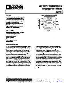
Timers – OCTO series. OM3. Installation design. Width 35mm. 8 functions. 8 time
ranges. Zoom voltage. 2 change over contacts. 1.04–7. Fusing: 8A fast acting.
OM3
Timers – OCTO series Installation design Width 35mm 8 functions 8 time ranges Zoom voltage 2 change over contacts
Technical data 1. Functions
E R Ws Wa Es Wu Bp Wt
ON delay OFF delay with control contact Single shot leading edge with control contact Single shot trailing edge with control contact ON delay with control contact Single shot leading edge voltage controlled Flasher pause first Pulse detection
2. Time ranges
Time range 1s 10s 1min 10min 1h 10h 1d 10d
Adjustment range 50ms 1s 500ms 10s 3s 1min 30s 10min 3min 1h 30min 10h 72min 1d 12h 10d
3. Indicators
Green LED ON: Green LED flashes: Yellow LED ON/OFF:
indication of supply voltage indication of time period indication of relay output
Fusing: Mechanical life: Electrical life: Switching frequency: Insulation voltage: Surge voltage:
8A fast acting 20 x 106 operations 2 x 10⁵ operations at 1000VA resistive load max. 60/min at 100VA resistive load max. 6/min at 1000VA resistive load (according to IEC 947-5-1) 250V AC (according to IEC 664-1) 4kV, overvoltage category III (according to IEC 664-1)
7. Control contact Connection: Loadable:
Line length: Control pulse length:
8. Accuracy
Base accuracy: Adjustment accuracy: Repetition accuracy: Voltage influence: Temperature influence:
9. Ambient conditions
4. Mechanical design
Self-extinguishing plastic housing, IP rating IP40 Mounted on DIN-Rail TS 35 according to EN 50022 Mounting position: any Shockproof terminal connection according to VBG 4 (PZ1 required), IP rating IP20 Initial torque: max. 1Nm Terminal capacity: 1 x 0.5 to 2.5mm² with/without multicore cable end 1 x 4mm² without multicore cable end 2 x 0.5 to 1.5mm² with/without multicore cable end 2 x 2.5mm² flexible without multicore cable end
Ambient temperature: Storage temperature: Transport temperature: Relative humidity: Pollution degree:
not potential free, terminals A1-B1 yes, parallel load min.1VA (0.5W) terminals A2-B1 max. 10m DC min. 20ms AC min. 50ms ±1% (of maximum scale value) ≤5% (of maximum scale value) 30% of the supply voltage
6. Output circuit
2 potential free change over contacts Switching capacity (distance < 5mm): 1250VA (5A / 250V) Switching capacity (distance > 5mm): 2000VA (8A / 250V
Release 11/01
1.04 – 7
OM3
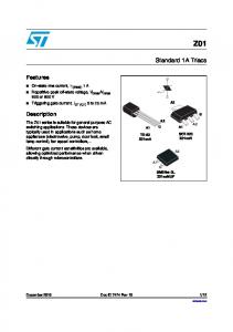
Functions ON delay (E) When the supply voltage U is applied, the set interval t begins (green LED flashes). After the interval t has expired (green LED illuminated) the output relay R switches into on-position (yellow LED illuminated). This status remains until the supply voltage is interrupted. If the supply voltage is interrupted before the expiry of the interval t, the interval already expired is erased and is restarted when the supply voltage is next applied.
OFF delay with control contact (R) The supply voltage U must be constantly applied to the device (green LED illuminated). When the control contact S is closed, the output relay R switches into on-position (yellow LED illuminated). If the control contact is opened, the set interval t begins (green LED flashes). After the interval t has expired (green LED illuminated) the output relay switches into off-position (yellow LED not illuminated). If the control contact is closed again before the interval t has expired, the interval already expired is erased and is restarted with the next cycle.
Single shot leading edge with control contact (Ws) The supply voltage U must be constantly applied to the device (green LED illuminated). When the control contact S is closed, the output relay R switches into on-position (green LED illuminated) and the set interval t begins (green LED flashes). After the interval t has expired (green LED illuminated) the output relay switches into off-position (yellow LED not illuminated). During the interval, the control contact can be operated any number of times. A further cycle can only be started when the cycle run has been completed.
Single shot trailing edge with control contact (Wa) The supply voltage U must be constantly applied to the device (green LED illuminated). Closing the control contact S has no influence on the condition of the output relay R. When the control contact is opened, the output relay switches into on-position(yellow LED illuminated) and the set interval t begins (green LED flashes). After the interval t has expired (green LED illuminated), the output relay switches into off-position (yellow LED not illuminated). During the interval, the control contact can be operated any number of times. A further cycle can only be started when the cycle run has been completed.
ON delay with control contact (Es) The supply voltage U must be constantly applied to the device (green LED illuminated). When the control contact S is closed, the set interval t begins (green LED flashes). After the interval t has expired (green LED illuminated) the output relay R switches into on-position (yellow LED illuminated). This status remains until the control contact is opened again. If the control contact is opened before the interval t has expired, the interval already expired is erased and is restarted with the next cycle.
Single shot leading edge voltage controlled (Wu) When the supply voltage U is applied, the output relay R switches into on-position (yellow LED illuminated) and the set interval t begins (green LED flashes). After the interval t has expired (green LED illuminated) the output relay switches into off-position (yellow LED not illuminated). This status remains until the supply voltage is interrupted. If the supply voltage is interrupted before the interval t has expired, the output relay switches into off-position. The interval already expired is erased and is restarted when the supply voltage is next applied.
Flasher pause first (Bp) When the supply voltage U is applied, the set interval t begins (green LED flashes). After the interval t has expired, the output relay R switches into on-position (yellow LED illuminated) and the set interval t begins again. After the interval t has expired, the output relay switches into off-position (yellow LED not illuminated). The output relay is triggered at a ratio of 1:1 until the supply voltage is interrupted.
Pulse detection (Wt) When the supply voltage U is applied (green LED illuminated), the output relay R switches into on-position (yellow LED illuminated). When the control contact S is closed, the set interval t begins (green LED flashes). So that the output relay remains in on-position, the control contact must be opened and closed again within the set interval t. If this does not happen, the output relay switches into off-position and all further pulses at the control contact are ignored. To restart the function the supply voltage must be interrupted and re-applied.
www.tele-power-net.com
Subject to alterations and errors
Connections