The design of TESLA beam delivery system (BDS) has undergone some major changes and upgrades in the past year. They are essentially motivated by the.
DAPNIA/SEA-00-16
TESLA Interaction Region Layout, Collimation and Extraction O. Napoly
�
y
and N.J. Walker
� CEA/Saclay, DAPNIA/SEA, France yDESY, Hamburg, Germany
Presented at the Linear Collider Workshop 2000 (LCWS 2000) October 24-28, 2000, FNAL, Batavia, IL, USA
TESLA Interaction Region Layout, Collimation and Extraction O. Napoly
�
y
and N.J. Walker
� CEA/Saclay, DAPNIA/SEA, France yDESY, Hamburg, Germany
Abstract.
We review the current design of the interaction region of the TESLA superconducting linear collider. We describe in particular the recent upgrades of the collimation section and the beam extraction lines.
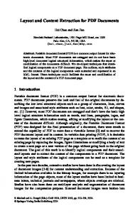
The design of TESLA beam delivery system (BDS) has undergone some major changes and upgrades in the past year. They are essentially motivated by the possibility to include a second interaction point (IP) and the decision to locate the undulator-based positron source upstream of the electron BDS, instead of at the electron dump line, as was the case in the TESLA Conceptual Design Report [1]. This paper brie y describes the 4 sub-systems which have been newly included or re-designed, namely the beam switch-yard [2], the collimation section [3], the fast emergency extraction line [4] and the main extraction line [5]. A general description of TESLA 500 GeV e+e; collider, including the BDS and, a discussion on machine detector interface are given elsewhere [6] in these proceedings. Figure 1 shows the geometry of the electron BDS, including the fast emergency extraction line (FEXL), and an indication of the location of the positron source system. The main e+e; IP has a transverse o�set with respect to the linac of 1.8 m, and a zero crossing-angle. The second IP, transversely o�set by about 25 m aside of the rst IP, realizes a crossing-angle of 34 mrad adequate for photon-photon collisions. Nevertheless, with the positron source located in front of the switch-yard, it can also be used for e+e; collisions.
I BEAM SWITCHYARD Starting immediately after the undulator, the beam switch yard is needed to serve the two IP's and to give space to the positron source (see Fig.1). The arc geometry should therefore allow clearance for the photon target and the associated positron capture system, while keeping the horizontal emittance growth due to synchrotron radiation to about 10%. The lattice is based on a double-bend achromat system used in modern light sources. The use of iron-core electro-magnets for the rst
FIGURE 1. Geometry of the primary e; BDS from linac to IP. dipoles common to both beamlines precludes fast intra-pulse switching between the two IRs but could in principle allow switching from pulse to pulse at 5 Hz.
II COLLIMATION AND DIAGNOSTICS SECTION The collimation section consits of the magnetic energy spoiler (MES), a dispersive section where non-linear elements blow-up the beam at the downstream energy collimator (ECOL) in the event of a large energy error (see Fig.2), and a betatron collimation and diagnostics section (CDS), a periodic 45� lattice where a series of spoilers and absorbers are used to collimate the beam halo (see Fig.3). Such a lattice also provides for an e�cient emittance measurement station using pro le monitors close to each spoiler location where the beam reaches relatively large sizes.
III EXTRACTION BEAM LINES The fast emergency extraction line (FEXL) provides the machine protection in case of a linac fault. The extraction point for the FEXL is placed just downstream of the MES: should a 2% o�-energy bunch train exit the linac, the BPM at the nonzero dispersive point in the MES send a signal to a fast kicker system. The beam is extracted horizontally, and then transported to a FODO section comprising both a
FIGURE 2. Concept of the magnetic energy spoiler (MES). horizontal and vertical bend which steers the beam down (� 15 mrad) to the main dump located 250 m in front of the IP (see Fig.1). The FEXL can also serve as a by-pass system during commissioning. The main extraction line brings the strongly disrupted beam from the colliding point to the main dump (from the other side than the FEXL). Extraction is done purely in the vertical plane (see. Fig.4). The initial kicks are given by an array of electrostatic separators (ESEP) and are completed by septum (MSEP) and dipole (BV) magnets to a downward angle of 15 mrad at the dump. To limit the beam losses to less than 0.1% along the beam line, the vertical dispersion is controlled by a proper quadrupole focusing (QED,QEF). The water dump is designed to absorb the 12 MW beam power but in order to limit the water local temperature rise to 40�C, the beam is swept by fast kickers (KIK) on a 3 cm circle in order to e�ectively increase the small spot size of the low-emittance undisrupted beam.
REFERENCES 1. R. Brinkmann, G. Materlik, J. Ro�bach and A. Wagner (eds.), Conceptual Design of a 500 GeV e+e- Linear Collider with Integrated X-ray Laser Facility, 2. J. Payet, O. Napoly, A Proposal for the TESLA High Energy Switchyard, TESLA 2000-24 (2000) 3. R. Brinkmann, N. Walker, G. Blair, The TESLA Post-linac Collimation System, TESLA 2001-12 (2001) 4. O. Napoly, J. Payet, N. Walker, Emergency Extraction High-Energy Beamline for TESLA, TESLA 2001-13 (2001) 5. E. Merker, I. Yazinin, O. Napoly, R. Brinkmann and N.J. Walker The TESLA HighPower Extraction Line, TESLA 2001-19 (2001) 6. O. Napoly, TESLA Linear Collider : Status Report, these proceedings. K. Bu�er Mask Design and Background Studies for TESLA these proceedings
FIGURE 3. The primary collimation and diagnostics system (CDS) .
FIGURE 4. Optics of the charges particle extraction line.