Abstract—We propose a procedure for generating compact test sets with enhanced at-speed testing capabilities for scan circuits. Compaction refers here to a ...
706
IEEE TRANSACTIONS ON COMPUTER-AIDED DESIGN OF INTEGRATED CIRCUITS AND SYSTEMS, VOL. 21, NO. 6, JUNE 2002
Test Compaction for At-Speed Testing of Scan Circuits Based on Nonscan Test Sequences and Removal of Transfer Sequences Irith Pomeranz, Fellow, IEEE, and Sudhakar M. Reddy, Fellow, IEEE
Abstract—We propose a procedure for generating compact test sets with enhanced at-speed testing capabilities for scan circuits. Compaction refers here to a reduction in the test application time, while at-speed testing refers to the application of primary input sequences that contribute to the detection of delay defects. The proposed procedure generates an initial test set that has a low test application time and consists of long sequences of primary input vectors applied consecutively. To construct this test set, the proposed procedure transforms a test sequence 0 for the nonscan circuit into a scan-based test by selecting an appropriate scan-in state and removing primary input vectors from 0 if they do not contribute to the fault coverage. If 0 contains long transfer sequences, several scan-based tests with long primary input sequences may be obtained by replacing transfer sequences in 0 with scan operations. This helps reduce the test application time further. We demonstrate through experimental results the advantages of this approach over earlier ones as a method for generating test sets with minimal test application time and long primary input sequences. Index Terms—At-speed testing, scan-based circuits, test application time, test compaction.
I. INTRODUCTION
T
EST COMPACTION is performed for scan designs in order to reduce the test application time and/or the memory requirements of the test set. Test compaction procedures for scan designs that attempt to minimize the test application time were described in [1]–[4]. In the procedures of [1]–[4], each test starts with a scan-in operation, followed by one or more primary input vectors applied using the functional clock of the circuit. A test ends with a scan-out operation. The procedures described in [1]–[3] are dynamic compaction procedures. They minimize the test application time by finding an appropriate balance between the number of primary input vectors applied consecutively using the functional clock (i.e., without using the scan chain) and the number of scan operscanned state variables, and ations. For a circuit with assuming that the scan clock and the functional clock have Manuscript received April 3, 2001; revised October 19, 2001. The work of I. Pomeranz was supported in part by the National Science Foundation under Grant CCR-0098091 and in part by SRC under Grant 2001-TJ-950. The work of S. M. Reddy was supported in part by the NSF under Grant CCR-0097905 and in part by SRC under Grant 2001-TJ-949. This paper was presented in part at the ACM/IEEE Design Automation Conference, June 2001. This paper was recommended by Associate Editor R. Aitken. I. Pomeranz is with the School of Electrical and Computer Engineering, Purdue University, West Lafayette, IN 47907 USA. S. M. Reddy is with the Electrical and Computer Engineering Department, University of Iowa, Iowa City, IA 52242 USA. Publisher Item Identifier S 0278-0070(02)02851-8.
the same cycle time, a scan-in/out operation can be replaced primary input vectors applied using the functional by clock, without increasing the test application time. Whenever it is possible to propagate fault effects and set the circuit state primary input vectors, scan operations to using fewer than achieve these goals can be avoided, and thus the test application time can be reduced. We point out that the decision to apply primary input vectors instead of using a scan operation also has an effect on the state memory requirements of the test set. For a circuit with primary inputs, and primary outputs, a scan variables, bits ( bits for the scan-in operation requires storage of bits for the fault-free scan-out vector). A sevector, and quence of primary input vectors requires storage of bits ( bits for the primary input sequence and bits for the fault-free primary output sequence). It is possible to ensure that the memory requirements are not increased by using a primary input sequence of length instead of a scan operation , or . if The procedure of [4] is a static compaction procedure, where test compaction is done as a postprocessing step following test generation. It is based on the operation of combining tests. A test , where is a scan-in is represented as is a sevector to be scanned in at the beginning of the test, quence of primary input vectors to be applied using the funcis scanned-in, and is the expected tional clock after is applied. Combining two fault-free scan-out vector after and consists of removing the scan operations retests and and concatenating and to obtain lated to . The resulting combined test the primary input sequence , where is the fault-free is is scanned-in and the sescan-out vector expected after and are applied. The quences of primary input vectors procedure attempts to combine as many test pairs as possible in order to remove scan operations, thus reducing the test application time (and the memory requirements). The combination of two tests is accepted only if it does not reduce the fault coverage. The procedure stops when no additional test pairs can be combined. Experimental results for full-scan circuits [4] show that the test application times obtained by this static compaction procedure are lower than the test application times obtained by the dynamic compaction procedures of [1]–[3]. This result was obtained by applying the procedure of [4] to a specific initial test set based on a combinational test set, such that all the test sequences in the initial test set are of length one.
0278-0070/02$17.00 © 2002 IEEE
POMERANZ AND REDDY: TEST COMPACTION FOR AT-SPEED TESTING OF SCAN CIRCUITS BASED ON NONSCAN TEST SEQUENCES
In [5] it was observed that functional tests detect some unique defects that are not detected by other tests. Functional tests are applied at-speed (i.e., using the functional clock of the circuit) and hence are capable of detecting delay defects that escape other types of tests. Similar observations were made in other studies [6]. However, functional tests may be long, and they may require long test application times. In order to reduce or eliminate the need for functional tests, other methods to generate and apply at-speed tests are needed. One such approach is based on increasing the proportion of functional clock cycles in the total number of clock cycles used in scan-based tests. An increased proportion of functional clock cycles implies an increased proportion of primary input vectors applied consecutively to the circuit-under-test. Even if the primary input vectors in a scan-based test are applied at a slower speed than the functional clock speed of the circuit, application of primary input vectors consecutively may help detect delay defects that are large enough to cause errors even at lower speeds. The closer the speed of application of the primary input vectors is to the functional clock speed of the circuit, the higher the delay defect coverage is expected to be. It is interesting to observe that the compaction procedures in [1]–[4] reduce the total number of clock cycles (i.e., they achieve reduced test application times) by increasing the lengths of the primary input sequences included in the various tests. Thus, these procedures increase the proportion of functional clock cycles. However, the number of primary input vectors applied consecutively can be significantly improved as demonstrated later in this paper. In this work, we propose a new approach to the derivation of tests for scan designs that reduces the test application time and increases the proportion of functional clock cycles used during test application. The proposed procedure achieves these objectives by initially generating a single test (or a small number of tests) with a relatively long primary input sequence, such that the test detects all or most of the target faults. If necessary in order to achieve complete fault coverage, the procedure adds tests with primary input sequences of length one. A test with a long primary input sequence is obtained by the generated for the proposed procedure from a test sequence nonscan sequential circuit. Test generation for nonscan sequential circuits can be performed efficiently for benchmark circuits as demonstrated in [7]. Nevertheless, if the time to compute a nonscan sequence is too high, it is also possible to use a random sequence or a sequence that detects a subset of the circuit faults. can be obtained If the number of faults detected is too low, by test generation starting from a fully specified initial state, which can also be used as a scan-in state for . The sequence is transformed into a scan-based test by preceding it with an appropriate scan-in vector and by scanning out the circuit state is applied. The sequence is compacted as much as after possible while selecting the scan-in and scan-out vectors. Another new compaction feature of the proposed procedure is based on the following observation. In some cases, the test may contain long transfer sequences that sequence based on do not detect any new faults and serve only to bring the circuit from the state obtained after the last fault was detected to a new state where a new fault can be activated. When such a transfer , we sequence is longer than the number of state variables
707
remove the transfer sequence and replace it by a scan operation. As a result, the test based on may be partitioned into several tests separated by scan operations. Experimental results show that overall, the test application times of the test sets generated by the proposed procedure are smaller than those reported earlier in [1]–[4], and the average primary input sequence length is significantly higher. We consider full-scan circuits in this work. The proposed procedure can be extended to the case of partial-scan circuits. Approaches to the reduction of test application time in scan circuits that do not involve test compaction were considered in [12]–[16]. At-speed BIST for scan circuits was considered in [17] and [18]. The paper is organized as follows. In Section II, we describe the proposed procedure for generating test sets that contain small numbers of tests, with relatively high average primary input sequence lengths. Experimental results obtained by applying this procedure to benchmark circuits are given in Section III. Section IV concludes the paper. II. THE PROPOSED PROCEDURE The proposed procedure generates a single test or a set of that contain long primary input sequences (signifitests cantly longer than one) and detect all or most of the target faults. or test set is generated based on a test seThe test that was generated for the circuit assuming that scan quence is not available. In addition, the proposed procedure may add to the test set a small number of tests with input sequences of length one if this is necessary in order to achieve complete fault coverage. from the deFor the discussion in this section, we omit scription of a test in order to simplify the notation and repre, where is a scan-in vector and sent as is a primary input sequence. The proposed procedure has five phases. The first phase crea single scan-based test by selecting a scan-in ates from and a time unit where scan-out will be performed. vector , where is a prefix of The resulting test is . as much as posThe second phase reduces the length of sible in order to reduce the test application time without reducing the fault coverage. Test length reduction is achieved by [8]. The resulting single test is omitting vectors from . Phases 1 and 2 are repeated several times to select and the shortest prithe most appropriate scan-in vector . The final test obtained is denoted by mary input sequence . The third phase checks whether obtained at the end of Phases 1 and 2 contains long transfer sequences that do not detect or activate any faults and can be substituted by scan operations in order to reduce the test application time without reducing the fault coverage. The third phase results in a test set that contains either a single test (if no transfer sequences were removed) or tests obtained by removing transfer sequences and replacing them by scan operations. The fourth phase adds tests for target faults that remain un. detected by
708
IEEE TRANSACTIONS ON COMPUTER-AIDED DESIGN OF INTEGRATED CIRCUITS AND SYSTEMS, VOL. 21, NO. 6, JUNE 2002
The proposed procedure can terminate after the fourth phase, or a fifth phase can be used that consists of static compaction of the resulting test set using a procedure that accepts a given test set. In the following subsections, we describe each one of the phases in more detail. A. Phase 1: Scan-Based Test The steps of the first phase that creates a single scan-based are described next. test from the test sequence 1) Step 1: In Step 1, we perform fault simulation of the nondetected by scan circuit to determine the set of faults without using scan. to be shifted 2) Step 2: In Step 2, we select a scan-in state in before is applied to the circuit. The scan-in state is selected so as to maximize the number of faults detected by the test under the assumption that the circuit state is scanned are detected out after the application of . The faults in and need not be simulated in this step. for any selection of the set of faults detected by . We have We denote by . Procedure 1 given below describes Step 2. As a source of candidate scan-in states, we use a combinational test set (i.e., a test set generated for the combinational logic of the circuit). is divided into a state vector and a primary Each test is used as a candidate scan-in input vector . Every vector is considered, the test is fault vector. When , where is the simulated. The set of faults considered is is the set of faults detected by set of all the target faults and . The subset of detected faults is denoted by . Once all the that results in the vectors have been considered, the vector is selected and assigned to . The set of faults largest set detected by is the set . for . Procedure 1: Selecting a scan-in state 1) Let be a combinational test set. Let be the set of target be the set of faults detected by . faults, and let : 2) For every under the set of faults Fault simulate . Let the subset of detected faults be . that results in the largest set . Set 3) Select the vector . Set . along after 3) Step 3: In Step 3, we select a time unit which application of input vectors will end and the circuit state by the will be scanned out. This is equivalent to replacing that consists of the first time units of sequence (we start labeling time units from zero). The result of this . The set of faults detected by step is a test is denoted by . The selection of guarantees that . . We Procedure 2 given below describes the selection of use the following notation in Procedure 2. For a sequence , the subsequence of that starts at time we denote by and ends after time unit . We denote the length of unit by . For a given time unit , we define a test that consists of the scan-in vector and the that ends after time unit . To select the time unit prefix of after which the state will be scanned out, we consider the tests
for . For until one of the following conevery , we fault simulate is found, which is not ditions is satisfied: 1) A fault . Since our goal is to maximize the number of detected by to be detected faults, we do not allow any fault detected by undetected by changing the scan-out state. The simulation effort is minimized by stopping the simulation process as soon as such a fault is identified. 2) All the faults have been simulated, are detected. In this case, we consider and all the faults in as a candidate to replace , and we store the detected . Since , it is guarfaults in a set will be found, for anteed that at least one candidate test . Of all the possible candidates, we select that has the smallest value of . We use . The re, and the set of detected faults is sulting test is denoted by . denoted by for . Procedure 2: Selecting be the set of faults detected by . 1) Let , we have the following. 2) For until one a) Fault simulate of the following conditions is satisfied: i) A fault is found, which is not detected by or ii) All the faults have been simulated, and all the are detected. Let be the set of faults in . faults detected by , b) If Condition ii) is satisfied, set and stop. that has the smallest value of Note that we select in order to reduce the primary input sequence length as much as possible. Alternatively, it is possible to select the test with the largest set and the smallest value of . This would maximize the number of detected faults as well as reduce the sequence length. However, our experiments indicated that instead of results in input sequences that are sigusing nificantly longer, while the increase in the number of detected faults is marginal compared to the use of . Overall, we oband not . tained better results by using B. Phase 2: Vector Omission that detects This phase starts from a test . The goal of this phase is to omit as many the set of faults without losing the detection of any vectors as possible from . This will reduce the test application time. of the faults in Vector omission is done similar to [8], and, therefore, we do not provide a detailed description here. The resulting test is denoted . by C. Iterative Application of Phases 1 and 2 , Phases 1 and 2 first define a scan-based test . The scan-out state is then adjusted to obtain . Finally, is compacted to obtain a test . It is now possible to repeat the process using instead of as the initial test sequence. The iterative application of Phases 1 and 2 is described in Procedure 3 below. Let us consider an arbitrary iteration of this process. Let the previous iteration result in . Iteration starts from the sequence Starting from
POMERANZ AND REDDY: TEST COMPACTION FOR AT-SPEED TESTING OF SCAN CIRCUITS BASED ON NONSCAN TEST SEQUENCES
709
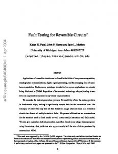
Fig. 1. Example sequence.
. The sequence is simulated without using scan in order to identify faults detected independent of the scan-in for is then selected out of the state. A scan-in state used earlier states defined by the combinational test set , The scan-out state is adjusted to obtain to obtain a new test and vectors are omitted from . Thus, at every iteration, the selection of a new scan-in state and a new scan-out time unit may increase the number of faults detected. The new scan-out time unit and the application of vector omission may reduce the input sequence length and the test application time. Vector omission may also increase the number of detected faults [8]. The iteration over Phases 1 and 2 terminates when the selected scan-in state has already been selected in an earlier iteration. This is implemented as follows. The tests in are initially is selected based on marked unselected. If a scan-in state , is marked selected. Procedure 1 is modified as follows. When Procedure 1 considers the tests in , preference is given to the selection of a test marked unselected. Thus, if two tests and yield the same fault coverage but one of them is marked selected, Procedure 1 uses the one marked unselected. Only if a higher fault coverage is achieved by a selected test, is such a test used. When Procedure 3 finds that Procedure 1 sebased on a test marked selected, the lected a scan-in vector iteration over Phases 1 and 2 terminates. This implies that if contains test vectors, at most iterations of Phases 1 and 2 will be performed. Procedure 3 is given next. Procedure 3: Iterative application of Phases 1 and 2. be the given test sequence and let be the given 1) Let combinational test set. Mark all the test vectors in unselected. in the nonscan circuit to find the set of faults 2) Simulate it detects. 3) Call Procedure 1 to select a scan-in state . In Procedure 1, if a choice exists between different vectors in that allow the largest number of faults to be detected, select a vector marked unselected. is based on and is marked selected, stop. 4) If 5) Mark selected. . 6) Call Procedure 2 to select a scan-out time unit and obtain a new test . 7) Compact and go to Step 2. 8) Set D. Phase 3: Long Transfer Sequences Phases 1 and 2 terminate with a test that detects a set of faults . In Phase 3, we consider transfer . A transfer sequence takes the sequences included in fault-free circuit from a state to a state without detecting any fault and without activating any fault in a way that leads to its detection. We define transfer sequences more accurately
below. A transfer sequence from state to state can be substituted by a scan operation where is scanned in. The . effect of the substitution is as follows. Let , and define and . We omit to ensure that the circuit is brought to state Note that before is applied. If the length of is and , where is the number of state variables of the circuit, this change reduces the test application time clock cycles. In terms of the ability to by , we observe the following. From detect all the faults in , no fault is detected by during the definition of . In addition, the faults detected by the application of after is applied do not require activation during . In the new tests we define, we bring the application of by using a scan the fault-free and faulty circuits to state operation at the beginning of . Consequently, all the faults are expected to be detected either by or by detected by . Exceptions due to masking of fault effects are discussed below. We identify transfer sequences during a single pass of fault starting from state simulation with fault dropping over , as follows. For every fault , we maintain in a variable the last time unit where was activated by before it was detected for the first time. We say that is activated at time unit if the fault-free and faulty circuits are in the same state at time unit , and either: 1) the fault-free and or 2) faulty circuits are in different states at time unit is detected at time unit . Initially, for every is simulated starting from time unit zero, fault . While if is activated by at time unit . We we set until is detected. If is detected continue to update to record the detection time at time unit , we set of . After it is detected, is dropped from simulation and and remain unchanged. and of detected faults, Using the variables we identify transfer sequences as follows. We define a varifor every time unit along . Our goal is to able only for time units included in transfer obtain for other time units. Initially, sequences, and for every time unit . For every detected fault , for every time unit such that we set . The time units for which do not participate in the activation of any fault where the activation leads to detection. These time units define the transfer sequences. is of length 25, For example, consider a circuit for which , and it detects faults , , , , and . Let , , , , , , , , and . These time units are shown in Fig. 1. by and by in Fig. 1. We mark
710
IEEE TRANSACTIONS ON COMPUTER-AIDED DESIGN OF INTEGRATED CIRCUITS AND SYSTEMS, VOL. 21, NO. 6, JUNE 2002
From Fig. 1, fault causes to be set to zero for and cause to be time units 0, 1, and 2; faults set to zero for time units 4–8 (the two faults overlap at time causes to be set to zero for units 6 and 7); fault causes to be set time units 13 and 14; and fault to zero for time units 20–24 We are left with three transfer seconsisting of time unit 3, consisting quences, consisting of time units 15–19. of times units 9–12, and The transfer sequences are marked in Fig. 1. In general, every sequence of consecutive time defines a transfer seunits for which quence. We denote the resulting transfer sequences by and their lengths by , respectively. We the time unit at which starts. We order denote by . the sequences such that , , For the example of Fig. 1, , , , and . Procedure 4 given below describes the substitution of transfer sequences by scan operations, and it is followed by an example to demonstrate this process. We use the following notation. We the vector at time unit of . We denote denote by the subsequence of that starts at time unit by and ends at time unit . We denote by the state that is applied the fault-free circuit reaches at time unit when . We use a variable as the index of the starting from state and a variable that indinext test defined based on at which the primary input sequence cates the time unit of of must start. Procedure 4: Substitution of transfer sequences by scan operations: 1) set 2) for sequences: if
and
; , where
a) define a new test and b) set . c) set
is the number of transfer
: such that ; ;
such that 3) define an additional test and , where is the length of . In the example of Fig. 1, the transfer sequences , , and were . Suppose that the circuit has three . We do not replace state variables. We first consider . it by a scan operation since . This sequence is of length four, Next, we consider , we define a and it starts at time unit 9. Since . After this test is defined, we set test to ensure ends. This will that the next test will start after to be omitted. Next, we consider . This cause sequence is of length five, and it starts at time unit 15. We . We set therefore define a test . Finally, we define a test
Fig. 2. Example of possibly undetected fault.
that includes the remaining time . We obtain a test set . units of in Next, we consider the detection of the faults the example of Fig. 1. We observe that every fault is guaranteed to be detected by , , or , as follows. For , , and , uses the same scan-in state and primary input sequence . For , the scan-in vector of brings the fault-free and as , and is the faulty circuits to their states at time unit that leads to the detection of . Similarly subsequence of for . A case where a fault may not be detected occurs if the activation and detection times of two faults are interleaved simin Fig. 1, and the transfer sequence preceding ilar to and their activation times is removed. Let us consider the case shown . In this case, we in Fig. 2 assuming that . define a test This test detects since the circuit is brought to the activation state of , and the primary input subsequence leading to its demay be activated by the tection is included in . However, , and the faulty cirsubsequence at time unit cuit may reach a state different from . In this case, masking may prevent from being demay not detect some of the faults detected. In general, . However, this is expected to be rare, and we did tected by not observe this effect for any one of the benchmark circuits we considered. We observed one case where the number of faults detected increased due to the replacement of transfer sequences by scan operations. This may be due to the additional scan-out operations performed. E. Phase 4: Complete Fault Coverage that detects a set of Phases 1–3 terminate with a test set . If any fault out of the set of target faults is left faults ), we add a test to detect it in Phase undetected (i.e., 4. The tests to be added are selected based on the combinational , as described next. We denote test set in this phase by . Initially, the set of tests added to . , we define a scan-based test For every where is the state vector included in , and is a sequence of length one that contains the primary input included in . Since is a complete test set that vector detects all the target faults, and since detects the same faults can be used to obtain complete as , the tests fault coverage. , under the faults We simulate every test , , and find the set of faults dein , we tected by . In addition, for every fault out of that defind the number of tests of the last test that detects it. The tect it, and the index
POMERANZ AND REDDY: TEST COMPACTION FOR AT-SPEED TESTING OF SCAN CIRCUITS BASED ON NONSCAN TEST SEQUENCES
TABLE I DETECTED FAULTS
711
TABLE III NUMBERS OF CLOCK CYCLES
TABLE II TEST SEQUENCE LENGTHS TABLE IV PRIMARY INPUT SEQUENCE LENGTHS
number tially,
and the index are found as follows. Ini. For , if detects , we set and . At the end of the simulation contains the index of the last test that detects process, and is the number of tests that detect . We point out differently, we could have found any that by updating other test that detects . Any test that detects can be used in the proposed procedure. . We find We select tests as follows. Let that has the minimum value of . We the fault that detects it, add it to , and drop from select the test all the faults detected by . We repeat this process is empty. Note that if , it is necessary until in in order to detect . Such tests are to include selected first by the procedure we use. and The final test set consists of .
F. Phase 5: Static Compaction It is possible to apply a static compaction procedure, which obcan accept any given test set, to the test set tained at the end of Phase 4 in order to further reduce the test application time. In our implementation, we apply the static compaction procedure of [4]. III. EXPERIMENTAL RESULTS We applied the proposed procedure to ISCAS-89 benchmark circuits and to ITC-99 benchmark circuits. For ISCAS-89 benchmark circuits, we use the combinational test sets from [9], and the test sequences generated by STRATEGATE [10] and compacted by the static compaction procedure of [11].
712
IEEE TRANSACTIONS ON COMPUTER-AIDED DESIGN OF INTEGRATED CIRCUITS AND SYSTEMS, VOL. 21, NO. 6, JUNE 2002
For ITC-99 benchmark circuits, the combinational test sets are selected out of a large set of random patterns, and the test sequences are the ones generated by PROPTEST [7]. We consider circuits for which it is possible to generate nonscan test sequences that achieve high fault coverage under the single observation time approach starting from the all-unspecified initial state. For cases where the test generation time for nonscan circuits is too high or the fault coverage is too low, it is possible to use a random input sequence as the initial test sequence , a test sequence that was generated for a subset of the circuit faults, or a sequence generated starting from a fully specified initial state. At the end of this section, we report results obtained by using a random input sequence of length 1000 as the initial test sequence . We also report results obtained by using a test sequence generated starting from a fully specified initial state as the test sequence . A fully specified initial state allows more faults to be detected using shorter test sequences than when the initial state is unknown. As a result, the test generation effort is reduced and the fault coverage is increased compared to the case where the initial state is unknown (which is the assumption made in [10] and [7]). The results obtained using test sequences from [10] or [7] are shown in Tables I–IV. In Table I, after the circuit name, we show the number of circuit flip–flops and the size of the combinational test set . We then show the total number of single stuck-at faults. Under column detected, we show the number (subcolumn ), the of faults detected by the test sequence obnumber of faults detected by the test tained at the beginning of Phase 3 before removing transfer sequences (subcolumn scan), the number of faults detected by the obtained at the end of Phase 3 after removing test set transfer sequences (subcolumn trans), and the number of faults detected by the final test set obtained at the end of Phase 4 (subcolumn final). We enter a dash under column trans when no transfer sequences are removed in Phase 3. In this case, consists of a single test and there is no change in the number of detected faults due to the removal of transfer sequences. It is important to note that all the detectable target faults are detected by the final test set. In Table II, under column seq length we show the length of (subcolumn ), the length of the primary input sequence obtained at the beginning of Phase 3 (subcolumn scan), and the after removing transfer setotal length of all the tests in quences in Phase 3. We enter a dash in this column if no transfer sequences are removed in Phase 3. Under column tests we show the number of tests after Phase 3 (subcolumn trans) and the number of tests added in Phase 4 to achieve complete fault coverage (subcolumn comb). In Table III, we compare the numbers of clock cycles required for the application of several test sets. For a given test , the number of clock cycles is computed as set , where is the number of state is the length of the sequence included variables and in . Under column [2, 3] of Table III, we show the number of clock cycles obtained by the dynamic compaction procedure of [2] and [3]. The results in [2] and [3] are better than the results obtained in [1]. Under column [4], we show the number of clock
TABLE V RUN TIME INFORMATION
TABLE VI RESULTS FOR RANDOM SEQUENCES
cycles required for applying an initial test set based on a combinational test set (where all the primary input sequences are of length one), followed by the number of clock cycles obtained after static compaction of this test set using the procedure of [4]. Under column proposed we show the number of clock cycles required for application of the test set obtained at the end of Phase 4 of the proposed procedure. We then show the number of clock cycles required for application of the test set obtained at the end of Phase 5 of the proposed procedure, where Phase 5 uses the static compaction procedure of [4]. For an overall comparison of the test application time, we include in the last row of Table III the total number of clock cycles obtained by every method for all the circuits except 35 932. We exclude 35 932 because of the dramatic reduction achieved by the proposed procedure for this circuit. In Table IV, we compare the lengths of the sequences of primary input vectors, which are applied consecutively, under the following test sets: 1) the compacted test sets obtained in [4], where the initial test set is based on a combinational test set; 2)
POMERANZ AND REDDY: TEST COMPACTION FOR AT-SPEED TESTING OF SCAN CIRCUITS BASED ON NONSCAN TEST SEQUENCES
713
TABLE VII RESULTS FOR SEQUENCES USING A SPECIFIED INITIAL STATE
the initial test sets obtained by the procedure proposed here (i.e., the test sets obtained at the end of Phase 4); and 3) the compacted test sets obtained by the procedure proposed here (i.e., the test sets obtained at the end of Phase 5). For every test set, we show the average length of a primary input sequence, and the range of primary input sequence lengths. detects a large perFrom Table I it can be seen that centage of the circuit faults The replacement of transfer sequences by scan operations never reduces the number of detected faults. In one case ( 11), the number of detected faults is increased. This may be due to the fact that the circuit state is observed during additional scan operations. From Table II it can be seen that vector omission and the removal of transfer sequences reduce the number of primary input vectors that need to be applied to the circuit. In many cases, only a small number of tests based on a combinational test set needs to be added to achieve complete fault coverage. From Tables III and IV it can be seen that starting from a as proposed in this work leads single nonscan test sequence overall to reduced test application times and to much higher average primary input sequence lengths compared to the case where static compaction is applied to a test set based on a combinational test set. Information about the run time of the proposed procedure is given in Table V. All the run times are cumulative, and all of them are normalized to the time it takes to fault simulate in the nonscan circuit. Under column the test sequence scan we show the normalized run time for generating the test obtained at the beginning of Phase 3 before removing transfer sequences. Under column trans we show the normalized run time at the end of Phase 3, after removing transfer sequences. Under column final we show the normalized run time until the final test set is obtained at the end of Phase 4. Until now we used for test sequences generated by the test generation procedures of [10] or [7]. For the results reported
in Table VI, we use random nonscan test sequences of length 1000 as . Table VI has the same columns as Tables I–III. In addition, the last column of Table VI shows the average length of a primary input sequence in the final compacted test set after Phase 5. The following points can be seen from Table VI. detects signifiIn most cases, a random test sequence cantly fewer faults than the test sequences from [10] or [7]. Nevertheless, the number of tests added in Phase 4 of the proposed procedure to ensure complete fault coverage is in many cases only slightly higher than the number of tests added when the sequence from [10] or [7] is used. The effect on the number of clock cycles varies. In some cases, the number of clock cycles is higher than that required using the test sequences from [10] or [7]. Comparing the total number of clock cycles under column cycles subcolumn comp of Table VI with the total number of clock cycles under column proposed subcolumn comp of Table III, it can be seen that using a random sequence increases the number of clock cycles by approximately as 10%. The average length of the primary input sequences when is similar to that obtained a random sequence is used for is generated by the procedure of [10] or [7]. One may when conclude that the proposed method can be used with a random initial test sequence . a test sequence generated for We also considered using as the nonscan circuit assuming that its initial state can be specified arbitrarily. A specified initial state simplifies the test generation process compared to the case where the initial state is unknown, since the test generation procedure needs to deal with fewer undetectable faults and the test sequences are shorter. Thus, we can also consider circuits for which the test generation procedures of [7] and [10], whose sequences were used earlier, fail to detect reasonable numbers of faults starting from the all-unspecified initial state. We used the underlying test generation procedure of [19] to perform test generation starting from an initial state derived from the first combinational test vector in the combinational test set . We imposed strict limits on the search
714
IEEE TRANSACTIONS ON COMPUTER-AIDED DESIGN OF INTEGRATED CIRCUITS AND SYSTEMS, VOL. 21, NO. 6, JUNE 2002
space explored by the procedure of [19] for every target fault, and therefore the procedure may not detect all the detectable target faults. The results are shown in Table VII in the same format as Table VI. Table VII supports the conclusions drawn from Table VI regarding the ability of the proposed procedure and produce test to utilize different initial test sequences as sets with low test application times and long primary input sequences. IV. CONCLUDING REMARKS We proposed a new approach to the generation of test sets with reduced test application times and enhanced at-speed testing capabilities for scan circuits. The proposed procedure where is a primary generates a test input sequence significantly longer than one. Alternatively, it with primary input sequences generates a set of tests significantly longer than one. These tests typically detect a large percentage of the circuit faults. In addition, if necessary, where includes the test set consists of tests a single primary input vector. These tests are added to detect or . The proposed faults that are left undetected by procedure was motivated by the observation that an existing static compaction procedure reduces the test application time of a test set by reducing the number of tests and increasing the lengths of their primary input sequences. By using a long primary input sequence to define the test set, the proposed procedure generates a test set with characteristics that are similar to those of compacted test sets obtained by the earlier procedure. We demonstrated through experimental results the advantages of the proposed procedure over earlier ones as a method for generating test sets with minimal test application time. We also showed that the proposed procedure generates tests with longer primary input sequences. ACKNOWLEDGMENT The authors thank the reviewers for their helpful comments on this work. REFERENCES [1] D. K. Pradhan and J. Saxena, “A design for testability scheme to reduce test application time in full scan,” in Proc. 10th VLSI Test Symp., Apr. 1992, pp. 55–60. [2] S. Y. Lee and K. K. Saluja, “An algorithm to reduce test application time in full scan designs,” in Proc. 1992 Int. Conf. Computer-Aided Design, Nov. 1992, pp. 17–20. [3] , “Test application time reduction for sequential circuits with scan,” IEEE Trans. Computer-Aided Design, vol. 14, pp. 1128–1140, Sept. 1995. [4] I. Pomeranz and S. M. Reddy, “Static test compaction for scan-based designs to reduce test application time,” in Proc. 7th Asian Test Symp., Dec. 1998, pp. 198–203. [5] P. C. Maxwell, R. C. Aitken, K. R. Kollitz, and A. C. Brown, “IDDQ and AC scan: The war against unmodeled defects,” in Proc. 1996 Int. Test Conf., Oct. 1996, pp. 250–258. [6] “Best methods for at-speed testing?,” in 16th VLSI Test Symp., Apr. 1998, Panel 3, p. 460. [7] R. Guo, S. M. Reddy, and I. Pomeranz, “PROPTEST: A property based test pattern generator for sequential circuits using test compaction,” in Proc. 36th Design Automation Conf., June 1999, pp. 653–659. [8] I. Pomeranz and S. M. Reddy, “On static compaction of test sequences for synchronous sequential circuits,” in Proc. 33rd Design Automation Conf., June 1996, pp. 215–220.
[9] S. Kajihara, I. Pomeranz, K. Kinoshita, and S. M. Reddy, “Cost-effective generation of minimal test sets for stuck-at faults in combinational logic circuits,” IEEE Trans. Computer-Aided Design, vol. 14, pp. 1496–1504, Dec. 1995. [10] M. S. Hsiao, E. M. Rudnick, and J. H. Patel, “Sequential circuit test generation using dynamic state traversal,” in Proc. 1997 Eur. Design Test Conf., Mar. 1997, pp. 22–28. [11] I. Pomeranz and S. M. Reddy, “Vector restoration based static compaction of test sequences for synchronous sequential circuits,” in Proc. Int. Conf. Computer Design, Oct. 1997, pp. 360–365. [12] A. Jas, J. Ghosh-Dastidar, and N. A. Touba, “Scan vector compression/decompression using statistical coding,” in Proc. VLSI Test Symp., 1999, pp. 114–120. [13] I. Hamzaoglu and J. H. Patel, “Reducing test application time for full scan embedded cores,” in Proc. Int. Symp. Fault-Tolerant Computing, July 1999, pp. 260–267. [14] A. Jas, B. Pouya, and N. A. Touba, “Virtual scan chains: A means for reducing scan length in cores,” in Proc. VLSI Test Symp., Apr. 2000, pp. 73–78. [15] A. Chandra and K. Chakrabarty, “Frequency-directed run-length (FDR) codes with application to system-on-a-chip test data compression,” in Proc. VLSI Test Symp., Apr. 2001, pp. 42–47. [16] I. Bayraktaroglu and A. Orailoglu, “Test volume and application time reduction through scan chain concealment,” in Proc. Design Automation Conf., June 2001, pp. 151–155. [17] H.-C. Tsai, K.-T. Cheng, and S. Bhawmik, “Improving the test quality for scan-based BIST using general test application scheme,” in Proc. Design Automation Conf., June 1999, pp. 748–753. [18] Y. Huang, I. Pomeranz, S. M. Reddy, and J. Rajski, “Improving the proportion of at-speed tests in scan BIST,” in Proc. Int. Conf. Computer-Aided Design, Nov. 2000, pp. 459–463. [19] I. Pomeranz and S. M. Reddy, “On generating compact test sequences for synchronous sequential circuits,” in Proc. EURO-DAC ’95, Sept. 1995, pp. 105–110.
Irith Pomeranz (M’89–SM’96–F’99) received the B.Sc. degree (summa cum laude) in computer engineering and the D.Sc. degree from the Department of Electrical Engineering at the Technion—Israel Institute of Technology in 1985 and 1989, respectively. From 1989 to 1990, she was a Lecturer in the Department of Computer Science at the Technion. From 1990 to 2000, she was a faculty member in the Department of Electrical and Computer Engineering at the University of Iowa. In 2000, she joined the School of Electrical and Computer Engineering at Purdue University, where she is currently a Professor. Her research interests include testing of VLSI circuits, design for testability, synthesis and design verification. Dr. Pomeranz was a recipient of the NSF Young Investigator Award, in 1993, and of the University of Iowa Faculty Scholar Award, in 1997. She serves as an Associate Editor of the ACM Transactions on Design Automation. She served as a Guest Editor of the IEEE TRANSACTIONS ON COMPUTERS January 1998 special issue on Dependability of Computing Systems, and as program co-chair of the 1999 Fault-Tolerant Computing Symposium.
Sudhakar M. Reddy (S’82–M’82–SM’85–F’87) obtained the undergraduate degree in electrical and communication engineering from Osmania University, India, the M.S. degree from the Indian Institute of Science, and the Ph.D. degree in electrical engineering from the University of Iowa, Iowa City, IA. He has been active in the areas of testable designs and test generation for logic circuits since 1972. Since 1968 he has been a member of the faculty of the Department of Electrical and Computer Engineering, University of Iowa, where he is currently a Professor. Dr. Reddy has been an Associate Editor and twice a Guest Editor of the IEEE TRANSACTIONS ON COMPUTERS. He is an Associate Editor of the IEEE TRANSACTIONS ON COMPUTER-AIDED DESIGN. In 1990, he was made a University of Iowa Foundation Distinguished Professor. He is a member of Tau Beta Pi, Eta Kappa Nu, and Sigma Xi.