the Two by One (TBO) [9] and the Essential Fault Pruning. (EFP) algorithms [4]. Given an initial test set, TBO tries to reduce the test set size by replacing two test ...
Proceedings of the International Conference on Computer-Aided Design, November 1998
Test Set Compaction Algorithms for Combinational Circuits � Ilker Hamzaoglu and Janak H. Patel Center for Reliable & High-Performance Computing University of Illinois, Urbana, IL 61801
Abstract This paper presents two new algorithms, Redundant Vector Elimination (RVE) and Essential Fault Reduction (EFR), for generating compact test sets for combinational circuits under the single stuck at fault model, and a new heuristic for estimating the minimum single stuck at fault test set size. These algorithms together with the dynamic compaction algorithm are incorporated into an advanced ATPG system for combinational circuits, called MinTest. MinTest found better lower bounds and generated smaller test sets than the previously published results for the ISCAS85 and full scan version of the ISCAS89 benchmark circuits.
1 Introduction Compact test sets are very important for reducing the cost of testing the VLSI circuits by reducing the test application time. This is especially important for the scan-based circuits as the test application time for these circuits is directly proportional to product of the test set size and the number of storage elements used in the scan chain. Small test sets also reduce the test storage requirements. Since even the problem of estimating the size of a minimum single stuck at fault test set for a given irredundant combinational circuit is proven to be NP-hard [10], several test set compaction algorithms based on different heuristics are proposed in the literature, e.g. static compaction [6], dynamic compaction [6], independent and compatible fault sets based test generation [1, 9, 12, 14], reverse order fault simulation [13], maximal compaction [12], rotating backtrace [12], double detection [8, 9], Two by one [9], Three by two [9], forced pair merging [4] and essential fault pruning [4]. Although these algorithms are successful in producing small test sets, the resulting test sets are still larger than the known lower bounds. This is because of the following two reasons; the previously published test set compaction � This research was supported in part by the Semiconductor Research Corporation under contract SRC 96-DP-109 and in part by DARPA under contract DABT63-95-C-0069.
algorithms are unable to compact the test sets any further, and the known lower bounds are not tight. In order to close this gap further, this paper addresses both of these problems. We present two new test set compaction algorithms, Redundant Vector Elimination (RVE) and Essential Fault Reduction (EFR), and a new heuristic for estimating the minimum single stuck at fault test set size. These algorithms and the dynamic compaction algorithm proposed in [6] are incorporated into an advanced ATPG system for combinational circuits [7], called MinTest. MinTest found better lower bounds and generated smaller test sets than the previously published results for the ISCAS85 and full scan version of the ISCAS89 benchmark circuits [2, 3]. The rest of the paper is organized as follows. Section 2 presents the definitions that will be used in this paper. Section 3 presents the RVE algorithm. The EFR algorithm is presented in Section 4. Minimum Test Set Size estimation heuristic is described in Section 5. The experimental results are given in Section 6. Finally Section 7 presents the conclusions.
2 Preliminaries In this section, we present the definitions that will be used in this paper. A test vector in a given test set is called an essential vector, if it detects at least one fault that is not detected by any other test vector in this test set. A fault is defined to be an essential fault of a test vector, if it is detected only by this test vector in a given test set [4, 9]. In other words an essential vector detects at least one essential fault. A test vector is redundant with respect to a given test set, if it does not detect any essential faults, i.e. all the faults detected by it are also detected by the other test vectors in this test set [9]. An essential fault efi of a test vector ti is said to be pruned, if a test vector tj = 6 ti in the test set is replaced by a new test vector t0j which detects efi , the essential faults of tj and the faults detected only by ti and tj [4]. If two faults can be detected by a single test vector, they are called compatible. Similarly two faults are called incompatible, if they cannot be detected by a single test vector. An incompatibility graph for a given set of faults, FS = f fi j 1 � i � n g, is defined as IG(FS) = (V, E) where V = f vi = fi j 1 � i � n g and E = f ej = (vk ; vl ) j vk and vl are incompatible, 1 � k � n and 1 � l � n g [1, 4, 9, 14]. A fault set is called an independent fault set, if all the faults in this
REDUNDANT VECTOR ELIMINATION (t : test vector)
f
Fault simulate test vector t for each fault that is not proven to be redundant For each fault i that is detected by vector t
f
g
g
f
ESSENTIAL FAULT REDUCTION (T : test set, NumIteration: int, MFL : int, MEFL : int)
f
For NumIteration times
f
f ++ f == ++ f == f Identify the vector tj 6= t that detects fi number essential faults[tj ]?? if (number of essential faults[tj ] == 0) then f drop vector tj from the test set For each fault fk that is detected by tj f detection count[fk ]?? if (detection count[fk ] == 1) then f Identify the vector tk 6= tj that detects fk number of essential faults[tk ]++ g g g g detection count[ i] if (detection count[ i ] 1) then number of essential faults[t] else if (detection count[ i] 2) then
f
3 Redundant Vector Elimination During automatic test pattern generation, some of the faults detected by the earlier test vectors may also be accidentally detected by the test vectors generated later. As a result as more vectors are generated during the ATPG process, a test vector generated earlier may become redundant. Redundant Vector Elimination (RVE) algorithm identifies these redundant vectors during test generation and dynamically drops them from the test set. As it is shown in Figure 1, RVE fault simulates all the faults in the fault list except the ones that are proven to be untestable, and it keeps track of the faults detected by each vector, the number of essential faults of each vector and the number of times a fault is detected. During test generation if the number of essential faults of a vector reduces to zero, i.e. the vector becomes redundant, it is dropped from the test set. As illustrated in the example below, RVE algorithm can reduce the size of a test set more than Reverse Order Fault Simulation (ROFS) [13]. This is because ROFS cannot identify a redundant test vector if some of the faults detected by it are only detected by the test vectors generated earlier. It can only identify a redundant vector, if all the faults detected by it are also detected by the test vectors generated later.
ti in T with less than MEFL essential faults
all ef pruned = true failure limit = 0 For each essential fault
f
pruned = false For each test vector
f
fj of ti
tk 6= ti t t i , fj )
pruned = Multiple Target Test Generation( k, if (pruned == true) then break
g if (pruned == true) then f
t
Update T by replacing k with the new test vector Fault simulate the new test vector
g else f g
Figure 1: RVE algorithm set are pairwise incompatible [1]. For a given combinational circuit an independent fault set of maximum size is called a maximum independent fault set. Since the problem of finding a maximum independent fault set is NP-hard [10], maximal independent fault sets are used in practice. Minimum test set size of a given combinational circuit under the single stuck at fault model is defined to be the minimum number of test vectors required to detect all the testable single stuck at faults in this circuit.
For each test vector
g
g
g
g
failure limit++ all ef pruned = false if (failure limit == MFL) then break
if (all ef pruned == true) then drop vector
ti from T
Figure 2: EFR algorithm Example: Consider the fault set ff1, f2 , f3, f4 g. Suppose that for this fault set the ATPG system generated the test set f t1 , t2 , t3 g in the given order, and t1 detects the faults f1 and f2 , t2 detects the faults f3 and f1 , and t3 detects the faults f4 and f3 . In this example, after t3 is generated, RVE algorithm detects that t2 becomes redundant and drops it from the test set. Thus it reduces the test set to f t1 , t3 g. However, ROFS cannot reduce the size of this test set. The performance of the RVE algorithm is similar to the Double Detection (DD) algorithm introduced in [8, 9], even though slightly different results may be produced because of the order of dropping redundant vectors. However, we are not proposing RVE as a standalone test set compaction algorithm, rather as the first step of a two-step compaction framework that includes both RVE and Essential Fault Reduction (EFR) algorithms. In addition to the number of essential faults for each test vector, which is also obtained by DD, EFR needs the additional information that is produced by RVE; faults detected by each test vector and the exact number of times each fault is detected by the current test set. If DD is used instead of RVE, then EFR itself should obtain this information. Since RVE spends most of its execution time for computing this information, the execution time of the RVE and EFR algorithms combined is smaller than the DD and EFR algorithms combined.
4 Essential Fault Reduction Since pruning an essential fault of a test vector decreases the number of its essential faults by one, if all the essential faults of a test vector is pruned then it becomes redundant,
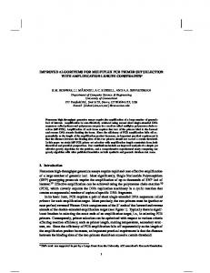
and it can be dropped from the test set. As it is shown in Figure 2 after the initial test set is generated, Essential Fault Reduction (EFR) algorithm is used iteratively to further compact the test set by pruning the essential faults of each vector as much as possible. EFR uses the Multiple Target Test Generation (MTTG) procedure [4, 9] to generate a test vector that will detect a given set of faults. EFR algorithm improves the Two by One (TBO) [9] and the Essential Fault Pruning (EFP) algorithms [4]. Given an initial test set, TBO tries to reduce the test set size by replacing two test vectors with a new one. This is achieved by finding a test vector that detects the essential faults of the both vectors as well as the faults detected only by these two vectors. However, even if it is not possible to find such a test vector, it may still be possible to eliminate these two test vectors from the test set. This may be achieved by a three by two algorithm (TBT) which tries to replace three test vectors with two new ones. In general, the algorithm can be extended to an N by M (M < N) algorithm. However, in the worst case, TBO needs to check O(V 2) vector pairs for possible compaction, where V is the number of test vectors in the initial test set, TBT needs to check O(V 3 ) vector triplets, and in general N by M algorithm needs to check O(V N ) vector sets. Thus, the N by M algorithm is computationally too expensive for N > 2, and implementation of an N by M algorithm where N > 2 is not reported. EFP, on the other hand, tries to reduce the test set size by trying to prune the essential faults of each test vector. If all the essential faults of a test vector is pruned, then this vector becomes redundant and it can be dropped from the test set. TBO can be seen as a special case of EFP in which a test vector is allowed to prune its essential faults by replacing only one vector. EFP achieves better performance than TBO by relaxing this restriction and allowing a test vector to prune its essential faults by replacing more than one vector in the test set. In the worst case, EFP will try to generate a test vector for O(E x V) fault sets, where E is the number of essential faults and V is the number of test vectors in the initial test set. Since in almost all cases E is larger than V, EFP is computationally more expensive than TBO. However, for N > 2 in most cases N by M algorithm is computationally more expensive. The problem of compacting a given test set can be viewed as distributing the essential faults of this test set to the given test vectors such that the number of redundant vectors is maximized. Therefore, the search space that should be explored is all possible distributions of the essential faults to the given test vectors. Since neither TBO nor EFP algorithms have this global view of the search space, they carry out a localized greedy search by concentrating only on removing one test vector at a time from the test set by pruning its essential faults. They prune an essential fault of a test vector only if this causes this vector to be redundant, otherwise they do not prune the essential fault. Because of this restriction, they only explore part of the search space.
Incompatibility Graph f1 f2 f3 f4 f5 f6 f7
f3 f4 f1 f2 f2
f7 f5 f7 f5 f7 f5 f3 f4 f5
f1 f2 f3 f5
Initial Test Set Test Vector t1 t2 t3 t4
Step 1
Faults Detected f1 f2 f3 f4 f5 f6 f7 Step 2
Test Vector
Faults Detected
Test Vector
Faults Detected
t1 t2 t3’ t4
f1 f2 f3 f4 f5 f6 f1 f7
t1’ t2 t3’ t4
f1 f2 f3 f3 f4 f5 f6 f1 f7
Step 3 Test Vector
Faults Detected
t1’ t2 t3’ t4’
f2 f3 f3 f4 f5 f6 f1 f7 f4
= Detected = Not Detected = Redundant
Figure 3: EFR Example EFR algorithm, on the other hand, has a global view of the search space. It overcomes the limitation of the TBO and EFP algorithms by carrying out a non-greedy global search by trying to distribute the essential faults to the given test vectors such that the number of redundant vectors is maximized. Therefore, even if a vector does not become redundant, EFR tries to reduce the number of its essential faults as much as possible by trying to prune as many of its essential faults as possible. Even if it fails to prune one of the essential faults of a test vector, it still tries to prune its other essential faults. This way EFR explores a larger portion of the search space than both TBO and EFP. As illustrated in the example below, using this new search technique EFR can produce smaller test sets than the ones produced by TBO, TBT, and EFP algorithms. Example: Consider the test set ft1, t2 , t3 , t4 g. Suppose that t1 detects the faults ff1, f2 g, t2 detects ff3 , f4g, t3 detects ff5 , f6 g and t4 detects ff7 g, and the adjacency list representation of the incompatibility graph is as given in Figure 3. EFR can reduce the size of this test set by one in the first iteration. As it is illustrated in Figure 3, this can be achieved by replacing the test vectors t1 with t01 that detects f2 and f3 , t3 with t03 that detects f1 , f5 , and f6 , and t4 with t04 that detects f4 and f7 . After these replacements t2 becomes redundant, thus it can be dropped from the test set. None of the TBO, TBT, and EFP algorithms can reduce the size of this initial test set. As illustrated in the example below, by means of the new search technique, EFR can further compact a given test set when it is used iteratively. This is not possible with TBO
Incompatibility Graph f1 f2 f3 f4 f5 f6 f7 f8 f9 f10
f4 f5 f6 f7 f8 f9 f10 f3 f4 f5 f7 f8 f9 f10 f2 f5 f6 f7 f8 f9 f10 f1 f2 f5 f6 f9 f10 f1 f2 f3 f4 f7 f8 f1 f3 f4 f7 f8 f9 f10 f1 f2 f3 f5 f6 f9 f10 f1 f2 f3 f5 f6 f9 f10 f1 f2 f3 f4 f6 f7 f8 f1 f2 f3 f4 f6 f7 f8
Initial Test Set Test Vector t1 t2 t3 t4 t5
f1 f3 f5 f7 f9
f2 f4 f6 f8 f10
Iteration 1
Iteration 2
Step 1
Step 1
Test Vector t1 t2 t3 t4’ t5
Faults Detected f1 f3 f5 f7 f9
f2 f4 f6 f8 f4 f10
Test Vector t1 t2’ t3 t4’ t5’
Faults Detected f1 f3 f5 f7 f9
f2 f4 f6 f8 f4 f10 f5
= Detected
Faults Detected f1 f3 f5 f7 f9
f2 f4 f1 f6 f8 f4 f10 f5
Step 2
Step 2 Test Vector t1 t2 t3 t4’ t5’
Faults Detected
Test Vector t1 t2’ t3’ t4’ t5’
Faults Detected f1 f3 f5 f7 f9
f2 f1 f6 f2 f8 f4 f10 f5
= Not Detected = Redundant
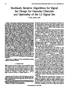
Figure 4: EFR Iteration Example and TBT. Although it is possible that EFP may further compact a given test set when it is used iteratively, this is very unlikely. Because this can only happen if one of the new test vectors “accidentally” detects one or more essential faults of the other test vectors that it is not intended to detect. This may make it possible to prune the essential faults of a test vector in the second iteration, even though it was not possible in the first iteration. Example: Consider the test set ft1, t2 , t3 , t4, t5 g. Suppose that t1 detects the faults ff1 , f2 g, t2 detects ff3 , f4 g, t3 detects ff5 , f6 g, t4 detects ff7 , f8 g, and t5 detects ff9 , f10 g, and the adjacency list representation of the incompatibility graph is as given in Figure 4. As it is illustrated in Figure 4, in the first iteration of the EFR algorithm only f4 will be pruned by replacing t4 with t04 , and f5 will be pruned by replacing t5 with t05 . Thus, in the first iteration EFR will not be able to reduce the test set size. However, since after the first iteration f4 is not an essential fault of t2 and f5 is not an essential fault of t3 anymore, in the second iteration f1 will be pruned by replacing t2 with t02 and f2 will pruned be repla-
cing t3 with t03 . Because of these t1 will become redundant, and it will be dropped from the test set. On the other hand, none of the TBO, TBT, and EFP algorithms can reduce the size of this initial test set. EFR has the same worst-case computational complexity as EFP, i.e. it will try to generate a test vector for O(E x V) fault sets, where E is the number of essential faults and V is the number of test vectors in the initial test set. If it is used iteratively then the worst-case complexity becomes O(I x E x V), where I is the number of iterations. An incompatibility graph is used for reducing the average case execution time of TBO and EFP algorithms [4, 9]. However, the incompatibility graph definition used in [1, 4, 9, 14] cannot represent the following incompatibilityrelation between stuck at faults. It is possible that even though a fault is pairwise compatible with all the faults in a given fault set, it may be incompatible with these faults when they are targeted together. Therefore, we extended the definition of the incompatibility graph by allowing a graph node to represent a set of faults. This new incompatibility graph is constructed in a demand-driven way during compaction. We have observed that using this incompatibility graph reduced the execution time of EFR algorithm.
5 Minimum Test Set Size Estimation To be able to assess the effectiveness of test set compaction algorithms for a combinational circuit, it is necessary to know the Minimum Test Set Size (MTSS) for this circuit. In addition if the MTSS is known, test set compaction time can be reduced by stopping the iteration of EFR algorithm whenever the minimum test set size is reached rather than iterating a predetermined number of times. Since the problem of computing the size of a minimum single stuck at fault test set for a given irredundant combinational circuit is proven to be NP-hard [10], heuristic techniques are used for finding a lower bound for MTSS. One of the most commonly used heuristics for finding a lower bound is finding the size of the maximal independent fault set. The size of the maximal independent fault set is less than or equal to the minimum test set size. The maximal independent fault set can be computed by finding the maximal clique in the incompatibility graph of the given single stuck at fault set [1, 4, 8, 9, 11, 14]. Since the problem of finding the maximal clique in a given graph is proven to be NP-complete [5], several heuristics are proposed for finding a maximal clique in a given incompatibility graph. Since the essential faults of the test vectors in a given test set are highly incompatible, in [4] it is suggested to compute the maximal clique by first considering only the essential faults and then enlarging this clique by considering the other faults. In [9], it is reported that for some circuits computing the maximal clique in the incompatibility graph that is constructed only by using the essential faults found larger cliques than computing the maximal clique in the incompatibility graph that is constructed by considering
all the faults. Based on the following theorem and the corollary, we also compute the maximal clique by first considering only the essential faults and then enlarging this clique by considering the other faults in the given fault list. Theorem 1: Given a complete single stuck at fault test set TS of size N for a combinational circuit, if there exists a maximal independent fault set MIFS of size K (N=2 � K � N) for this circuit, then that MIFS contains at least 2K-N essential faults each from a different test vector. Proof: If there exists a maximal independent fault set MIFS of size K, then by definition there are K pairwise incompatible faults in MIFS. Since the faults in MIFS are pairwise incompatible, no test vector can detect more than one fault in MIFS. Therefore each fault in MIFS should be detected by a different test vector in TS. Since the test set is complete, at least K test vectors in TS detect these K faults. If none of these K faults are detected by any of the remaining N-K test vectors in TS, then each one of them is an essential fault of a different test vector in TS. In the worst case, each one of the remaining N-K test vectors detects a different fault in MIFS. Since these N-K faults are detected by two vectors, they are not essential faults. Therefore, in the worst case, K(N-K) = 2K-N of the faults in MIFS is an essential fault of a different test vector in TS. In other words, MIFS contains at least 2K-N essential faults each from a different test vector.
2
Corollary: Given a complete single stuck at fault test set TS of size N for a combinational circuit, if there exists a maximal independent fault set MIFS of size N for this circuit, then that MIFS contains one essential fault from each test vector in TS. Proof: According to Theorem 1, MIFS should contain one essential fault from at least 2K-N test vectors in TS where K is the size of the maximal independent fault set. For K=N the expression 2K-N is equal to N. Since TS has N test vectors, this means that MIFS should contain one essential fault from each test vector in TS. 2 Theorem 1 shows that the maximal clique in the incompatibilitygraph of a small test set is likely to contain many essential faults, and the corollary indicates that for a minimum size test set if there exists a clique of this size in the incompatibility graph then the clique contains only essential faults. Since EFR algorithm produces test sets that are either minimum size or very close to it, based on this theorem, we compute the lower bound for MTSS by searching for the maximal clique that includes one essential fault from as many test vectors as possible in the test set produced by EFR algorithm and then enlarging this clique by considering the other faults in the given fault list. Since the size of the search space for computing the maximal clique by choosing one essential fault from as many test vectors as possible is very large, it is computationally too expensive to search it exhaustively. If there are n vectors ft1, t2 , : : :, tn g in the test set, and if the sizes of their essential fault sets are ef s1 , ef s2 , : : :, ef sn respectively, then the size
Qn
of the search space is O( i=1 ef si ). Therefore, we propose the following new heuristic to guide the branch and bound search algorithm. When trying to choose an essential fault from each test vector, consider the vectors in ascending order of the number of essential faults that they have, and explore more branches for the initial test vectors. This heuristic increases the probability of computing the maximal clique in a short amount of time because of the following reason. Once an essential fault is included in a clique, this reduces the number of essential faults of the remaining test vectors that can be included in this clique. If a test vector ti has ef si essential faults and if each one of these essential faults is equally likely to be in the maximal clique, then when trying to select an essential fault of this test vector the probability of choosing the essential fault that is in the maximal clique is 1=ef si . If the number of essential faults of ti that can be included in the maximal clique decreases, the probability of selecting the essential fault that is in the maximal clique increases. Since for the test vectors with small number of essential faults the probabilityof selecting the essential fault that is in the maximal clique is already high, and after selecting these essential faults, for the test vectors with larger number of essential faults the probability of selecting the essential fault that is in the maximal clique increases, considering the vectors with smaller number of essential faults first increases the overall probability of computing the maximal clique in a short amount of time.
6 Experimental Results We incorporated the minimum test set size estimation, RVE and EFR algorithms that we propose and the dynamic compaction algorithm proposed in [6] into our advanced ATPG system for combinational circuits [7], called MinTest. MinTest is designed in an object-oriented style and implemented in C++. We tested MinTest on the ISCAS85 and full scan version of the ISCAS89 benchmark circuits [2, 3]. The performance results for MinTest are obtained on a 200 MHz Pentium Pro PC with 128MB RAM running Linux 2.0.0 using GNU CC version 2.8.0. We compared the performance of MinTest on minimum test set size estimation with the previously published results and presented the comparision of the performance results in Table 1. The “–” sign in the table indicates that the lower bound for this circuit is not reported. The results show that our algorithm computed better lower bounds than the previously published ones. For 38 out of 40 circuits, the lower bounds computed by our algorithm are greater than or equal to the best published lower bounds. For 14 of these 38 circuits our algorithm computed as much as 33% larger lower bounds than the previously published results, e.g. 25% larger for c7552, 33% larger for s1423 and 11% larger for s9234. These 14 new lower bounds are indicated by an asterisk (*) in the table. Our minimum test set size estimation algorithm is applicable to large circuits, and its execution time is similar to the
[8] Circuit c432 c499 c880 c1355 c1908 c2670 c3540 c5315 c6288 c7552 TOTAL s208 s298 s344 s349 s382 s386 s400 s420 s444 s510 s526 s526n s641 s713 s820 s832 s838 s953 s1196 s1238 s1423 s1488 s1494 s5378 s9234 s13207 s15850 s35932 s38417 s38584 TOTAL
[4] 24 52 12 84 94 40 80 37 5 49 477 – – – – – – – – – – – – – – – – – – – – – – – – – – – – – – –
Loc 20 50 9 82 91 38 67 22 6 26 411 26 19 13 13 25 62 24 42 24 53 34 34 19 19 90 91 74 65 59 61 14 98 97 85 84 233 89 – 50 – 1597
Glb 20 50 10 82 68 39 65 36 6 28 404 27 20 13 12 25 62 23 43 23 53 35 35 19 19 90 91 75 68 99 107 15 98 97 92 88 233 85 – 60 – 1707
[9] – – – – 99 42 – – – 52 – – – – – – 63 – – – – – – – – – – – 73 105 115 – 100 100 – 90 – 90 9 – 93 –
[11] 27 52 – – – – – – – – – 27 23 13 13 25 63 24 43 24 54 49 49 21 21 93 – – – – – – – – – – – – – – – –
MinTest LB Time 27 15.0 52 0.1 � 21.9 84 0.9 � 88.1 � 47.1 78 174.5 37 748.6 6 347.7 � 663.8 512 2107.7 27 0.1 23 0.1 13 0.3 13 1.1 25 0.1 63 0.1 24 0.1 43 0.3 24 0.1 54 1.9 49 2.5 49 2.2 21 2.0 21 2.7 93 86.3 � 21.6 75 430.7 � 84.7 � 161.0 � 920.7 � 9.9 � 28.7 100 62.3 � 198.4 � 6319.4 233 722.7 � 938.9 9 5687.4 � 12287.9 89 10134.5 1922 38108.7
13 106 44 65
94 76 112 121 20 101 97 100 91 62
Table 1: Lower Bounds on Minimum Test Set Size algorithms presented in [8, 9]. The algorithm presented in [11] can only be applied to small circuits, and for these circuits our algorithm computed the same lower bounds with this algorithm. The algorithm presented in [4] is a computationally expensive algorithm, and neither its execution time for ISCAS85 circuits nor its performance for ISCAS89 circuits is reported. The performance of MinTest on test set compaction is compared against the two best test set compaction algorithms published in the literature, CompacTest (CT) [8, 9, 12] and TSC [4]. The comparison of the performance results is presented in Table 2. In the table, the smallest known test size for each circuit is marked by an asterisk (*). The largest known lower bound on the minimum test set size of each circuit is presented in the LB column. Some of these lower bounds are computed by our minimum test set size estimation algorithm and the rest is taken from [9]. In all the experiments, a backtrack limit of 6 is used in MinTest. The exe-
cution times of MinTest include fault simulation and initial test set generation times, and all the test sets generated by MinTest have 100% fault coverage. The performance results for CT and TSC are taken from [9] and [4] respectively. The performance of TSC for ISCAS89 circuits is not reported. The following observations can be made from the experimental results. For all the circuits, sizes of the test sets generated by MinTest are smaller than or equal to the best published results. For 31 out of 40 circuits, sizes of the test sets generated by MinTest are equal to the known lower bounds for these circuits. Even by executing only one iteration of EFR algorithm, MinTest generated smaller test sets than both CT and TSC for both ISCAS85 and ISCAS89 circuits. Moreover, for some circuits MinTest produced even smaller test sets by executing EFR algorithm iteratively. The test sets generated by MinTest are as much as 23% smaller than the previously published results, e.g. 16% smaller for c5315, 23% smaller for s1423, and 20% smaller for s38417. In order to measure the performance of EFR algorithm when it is used iteratively, we iterated it 3 times for the circuits for which the lower bound is not achieved after the first iteration. As it can be seen in the column headed “3 its”, for some of these circuits MinTest produced even smaller test sets when EFR is used iteratively. When EFR algorithm is iterated more than 3 times, MinTest produced even smaller test sets for nine circuits. These results are presented in the column headed “> 3 its”. Next to the test set sizes presented in the columns headed “3 its” and “> 3 its”, we indicated the iteration number that this test set size is reached in parenthesis. The times presented in the column headed “> 3 its” are the execution times of MinTest only for this many iterations. The CT and TSC execution times presented in Table 2 are obtained on a SUN SPARC 2 workstation. The compaction times presented for CT and MinTest include the initial test generation time as well. However, the compaction times presented for TSC only show the execution time of TSC starting from a given initial test set. Since MinTest is exploring a larger search space, its execution time is larger than that of CT. In [4], it is reported that to be within a reasonable running time, currently, TSC is only applicable to the medium size circuits with the largest being c7552. However, the experimental results show that MinTest is applicable to large circuits.
7 Conclusions This paper presented two new algorithms for generating compact test sets for combinational circuits under the single stuck at fault model, and a new heuristic for estimating the minimum single stuck at fault test set size. These algorithms together with the dynamic compaction algorithm are incorporated into an advanced ATPG system for combinational circuits, called MinTest. MinTest found better lower bounds and generated smaller test sets than the previously published results for the ISCAS85 and full scan version of the ISCAS89
Test Set Size Circuit c432 c499 c880 c1355 c1908 c2670 c3540 c5315 c6288 c7552 TOTAL s208 s298 s344 s349 s382 s386 s400 s420 s444 s510 s526 s526n s641 s713 s820 s832 s838 s953 s1196 s1238 s1423 s1488 s1494 s5378 s9234 s13207 s15850 s35932 s38417 s38584 TOTAL
LB 27 52 13 84 106 44 80 37 6 65 514 27 23 13 13 25 63 24 43 24 54 49 49 21 21 93 94 75 76 113 121 20 101 100 97 100 233 91 9 62 93 1927
CT 29 �
TSC 29 53 18 86 � �
91 44 14 80 566 � 24 15 14 � � � � � �
90 46 14 76 562 – – – – – – – – – – – – – – – – – – – – – – – – – – – – – – –
52 21 84�� 106 106 45 44
27 25 63 24 43 24 54
50 50 22 22 94 � � �
94 75 76
118 124 26 � �
101 100
103 108 235 �
95
13 85 115 2019
1 it � �
27 52 20 84�� 106� 44 87 41 13 �
73
547
27� 23� 13� 13� 25� 63� 24� 44 24�� 54 49�� 49� 21 21�
Time (secs) MinTest 3 its – – 18(2) – – – 87 40(3) 13 73 544 – – – – – – – � (2) – – – – – – � (2) 95 � (2) – – 122 22 – – – 106 – 96 12 � (3) � (3) 1968
43
94 95 76 � �
76 113
122 22 � � �
101 100 97 106 233� 96 12� 70 111 1974
93 75
68 110
> 3 its – – � (10) – – – � (15) � (12) � (8) – 535 – – – – – – – – – – – – – – – � (12) – – – � (4) � (25) – – – � (5) – � (17) – – – 1962
16
84 37 12
94
121 20 105 95
CT 7 5 12 16 55 130 262 362 398 1311 2558 0.8 1.5 1.5 1.7 1.7 3.8 1.8 3.2 2.3 6.0 4.9 4.9 3.1 4.6 19 20 13 25 48 102 32 40 43 216 1085 1096 1375 8388 13210 14446 40199.8
TSC 13.6 13.2 36.4 58.5 257.8 246.1 423.1 1126.3 419.4 1931.8 4526.2 – – – – – – – – – – – – – – – – – – – – – – – – – – – – – – –
1 its 6.2 17.4 10.4 29.4 78.9 73.3 178.1 265.4 65.6 794.7 1519.4 0.4 0.7 0.7 0.7 0.8 3.1 0.8 2.1 0.9 3.6 3.0 3.3 2.1 2.8 27.7 23.9 11.9 30.3 43.6 68.7 14.6 75.1 80.4 131.5 1103.6 1178.4 1406.1 10075.7 11773.6 17219.7 43289.8
MinTest 3 its – – 20.5 – – – 305.1 573.8 134.5 1733.8 – – – – – – – – 2.9 – – – – – – 34.1 28.7 15.3 – – 90.8 31.0 – – – 2020.7 – 2189.3 11334.5 28955.8 38538.9 –
> 3 its – – 50.9 – – – 1372.9 1983.5 306.9 – – – – – – – – – – – – – – – – – 80.1 – – – 127.4 205.3 – – – 3157.1 – 9252.2 – – – –
Table 2: Compaction Results benchmark circuits.
References [1] S. B. Akers, C. Joseph, and B. Krishnamurthy, “On the Role of Independent Fault Sets in the Generation of Minimal Test Sets”, in Proc. of the Int. Test Conf., pp. 1100-1107, August 1987. [2] F. Brglez and H. Fujiwara, ”A Neutral Netlist of 10 Combinational Benchmark Designs and a Special Translator in Fortran”, in Proc. of the Int. Symp. on Circuits and Systems, June 1985. [3] F. Brglez, D. Bryan, and K. Kozminski, ”Combinational Profiles of Sequential Benchmark Circuits”, in Proc. of the Int. Symp. on Circuits and Systems, pp. 1929-1934, May 1989. [4] J.-S. Chang and C.-S. Lin, “Test Set Compaction for Combinational Circuits”, IEEE Trans. on Computer-Aided Design, pp. 1370-1378, November 1995. [5] M. R. Garey and D. S. Johnson, Computers and Intractability: A Guide to the Theory of NP-Completeness, W. H. FreeMan, 1979. [6] P. Goel and B.C. Rosales, “Test Generation and Dynamic Compaction of Tests”, in Digest of Papers 1979 Test Conf., pp. 189-192, October 1979. [7] I. Hamzaoglu and J. H. Patel, “New Techniques for Deterministic Test Pattern Generation”, in Proc. of the IEEE VLSI Test Symp., pp. 446452, April 1998.
[8] S. Kajihara, I. Pomeranz, K. Kinoshita and S. M. Reddy, “Cost Effective Generation of Minimal Test Sets for Stuck at Faults in Combinational Logic Circuits”, in Proc. of the Design Automation Conf., pp. 102-106, June 1993. [9] S. Kajihara, I. Pomeranz, K. Kinoshita and S. M. Reddy, “Cost Effective Generation of Minimal Test Sets for Stuck at Faults in Combinational Logic Circuits”, IEEE Trans. on Computer-Aided Design, pp. 1496-1504, December 1995. [10] B. Krishnamurthy and S. B. Akers, “On the Complexity of Estimating the Size of a Test Set”, IEEE Trans. on Computers, pp. 750-753, August 1984. [11] Y. Matsunaga, “MINT - An Exact Algorithm for Finding Minimum Test Sets”, IEICE Trans. Fundamentals, pp. 1652-1658, October 1993. [12] I. Pomeranz, L. Reddy, and S. M. Reddy, “Compactest: A Method To Generate Compact Test Sets for Combinational Circuits”, in Proc. of the Int. Test Conf., pp. 194-203, October 1991. [13] M. H. Schulz, E. Trischler, and T. M. Sarfert, ”SOCRATES: A highly efficient automatic test pattern generation system”, IEEE Trans. on Computer-Aided Design, pp. 126-137, January 1988. [14] G.-J. Tromp, “Minimal Test Sets for Combinational Circuits”, in Proc. of the Int. Test Conf., pp. 204-209, October 1991.