Australasian Conference on Robotics and Automation (ACRA), December 2-4, 2009, Sydney, Australia
Texture Recognition by Tactile Sensing Nawid Jamali∗ , Philip Byrnes-Preston† , Rudino Salleh∗ and Claude Sammut∗ ∗ ARC Centre of Excellence for Autonomous Systems ∗† University of New South Wales, Sydney, Australia {nawidj, rudinos, claude}@cse.unsw.edu.au
[email protected]
Abstract Tactile sensing is essential for effective manipulation. A detailed understanding of the surface texture can also be used for industrial tasks such as quality assurance. This paper describes an application of machine learning in tactile sensing. A naive Bayes classifier is used to distinguish textures sensed by bio-inspired artificial finger. The finger has randomly distributed strain gauges and Polyvinylidene Fluoride (PVDF) films embedded in silicone. The data from the finger are preprocessed and the Fourier coefficients of the sensor outputs are used to learn a classifier for different textures. The finger is capable of distinguishing natural textures but in this paper we describe experiments on artificial textures, which we use to calibrate the learner.
1
Introduction
There is increasing interest in humanoid robots that are intended to work alongside humans in unstructured, “human-centric” environments. To be able to operate in such environments, the humanoids need to be able to dextrously manipulate objects[Brooks et al., 2004]. Humans have sophisticated tactile perception. They can perform complex tasks such as distinguishing between different textures, grasping objects of different shapes and sizes, and avoiding slip while applying minimal force to the grasped object. The capability for such a diverse skill-set can be attributed to the well developed tactile perception at the finger-object contact[Howe, 1994]. We learn much of our tactile perception by interacting with the environment. Observing tactual exploration of children, they carefully interact with the objects in the world, repeatedly trying to pick up an object, learning to perceive the world through their tactile sensors. If robots are to develop similar perception, they must also be able to learn. Most of the research in tactile sensing
has focused on building and characterising transducers. Very little work has been done on learning. The major contribution of this paper is a learning system for an artificial finger to differentiate between different textures. A bio-inspired robotic finger is developed to provide the sensory information for the learner. The finger is made of silicone with randomly distributed strain gauges and PVDFs. The sensory output from the finger is used to learn to distinguish between different textures. Texture classification is based on the Fourier coefficients of the sensor signals. Results from an experiment, where the finger successfully classifies ten different artificial textures is presented. The purpose of the experiment was to calibrate the artificial finger and test the proposed learning system. Experiments to distinguish between natural surfaces are in progress. These surfaces include carpet, two flooring vinyls with different textures, a tile with smooth surface, a tile with textured surface and a sponge. These results are currently being analysed.
2
Background
Our research is comprised of two equally important components, the development of artificial tactile sensors and the design and application of machine learning algorithms to interpret the sensory information. The following sections provide an overview of existing work in these two areas.
2.1
Artificial Tactile Sensors
In an attempt to equip robots with dexterity to match that of humans, the past three decades has seen increased research in the development of an artificial sense of touch. A great deal of effort has been devoted to developing tactile sensors that can provide sufficient information for dexterous manipulation. Many physical phenomena have been used to create tactile sensors. These include capacitive[Papakostas et al., 2002], piezo-resistive1 , optical[Hellard and Russel, 2002; 1
Pressure Profile Systems
Australasian Conference on Robotics and Automation (ACRA), December 2-4, 2009, Sydney, Australia
Ohka et al., 2004; Ohmura et al., 2006; Danisch and Reimer, 1999] , and magnetic[Torres-Jara et al., 2006]. Knowledge of all three components of force plays a crucial role in acquiring tactile perception. Attempts have been made to build sensors which can provide all three components of force[Ohka et al., 2004; Torres-Jara et al., 2006]. However the resultant sensors are hard to replicate or are too bulky to acquire acceptable spatial resolutions. Commercial sensors provide good spatial resolution but they have two major disadvantages. Firstly, they only react to stimuli normal to the surface of the sensor. Secondly, the gain in spatial resolution comes at the cost of lower temporal resolution. To decrease the wiring complexity of the sensors, commercial sensors apply scanning techniques to acquire data. Hence an increase in the spatial resolution equates to a decrease in temporal resolution. Some researchers have taken advantage of Micorelectromechanical Systems (MEMS) to manufacture tactile sensors with capability to provide force and temperature information[Engel et al., 2004]. MEMS based sensors are very attractive for use in robotics because of their small size and capability to provide multiple modes of transduction. However, their development is in the early stages and require a lot of resources to replicate. The sensors discussed so far are surface sensors i.e. they are attached to the surface of the robot fingers. Human hands use multiple sensors at different depths. Using human fingers as an inspiration, soft fingers with randomly distributed receptors at different depths have been developed[Hosoda et al., 2006]. The novelty of this approach lies in the absence of any need for calibration, the robot has to learn how to acquire meaningful information such as slip conditions and object texture through the interaction with the environment. These qualities make this sensor of particular interest for machine learning experiments.
2.2
Artificial Tactile Perception
Application of machine learning to tactile sensors is in its infancy. Some researchers have developed models of the sensor’s response to physical stimuli and show that the signals from the actual sensors match that of the model [Ohka et al., 2005]. Others have demonstrated, without the application of machine learning, that the signals produced by the transducers are significantly different for different materials and hence should be able to differentiate between different surface textures[Tada et al., 2004]. This work has not found its way into robotics. These sensors can be integrated with machine learning to provide far superior performance and equip robots with tactile perception comparable to that of humans. The past decade has seen a slow move from pure trans-
ducer manufacturing. Machine learning has been applied to various physical phenomena such as detection of slip condition and differentiating between different surface textures. Artificial Neural Networks (ANN) have been used to fuse vision and tactile sensory information to improve the accuracy of 3D object recognition[Kim et al., 2004], differentiate between different objects found commonly in a shopping bag[Taddeucci et al., 1997], and to detect slip [Fujimoto et al., 2003; Tada et al., 2005].
3
Sensor Design
A finger inspired by human tactile sensors has been developed. In this section, we give a brief overview of human tactile sensors. This is followed by description of a robotic finger that mimics human tactile sensors.
3.1
Biological Tactile Sensors
Human tactile sensors can be divided into two broad categories namely, slowly adapting (SA) and fast adapting (FA) receptors. Slowly adapting receptors respond to low frequency stimuli. In other words they provide static properties of a stimulus. On the other hand fast adapting receptors provide transient properties of the stimulus.
Figure 1: Human mechanorecpetors2 Human fingers are composed of two layers, called the dermis and epidermis respectively. The dermis and the epidermis interdigitate in a pattern that mimics the surface ridges on the skin. The receptors closer to the surface of the finger are categorised as type I and the ones deeper in the finger are categorised as type II. Type I receptors have smaller receptive field, while type II receptors have larger receptive fields (Figure 1). Each of these mechanoreceptors is responsible for a particular property of mechanical stimuli[Russell, 1990]: 2 Courtesy of http://grants.hhp.coe.uh.edu/clayne/ 6397/Unit4_files/image019.jpg
Australasian Conference on Robotics and Automation (ACRA), December 2-4, 2009, Sydney, Australia
• SA I - Merkel disk: These receptors are thought to provide information about shape, edges and texture. They respond to stimuli in 2-32Hz range. • SA II - Ruffini corpuscle: These receptors are stimulated by lateral skin stretch. They respond to stimuli in 1-16Hz range.
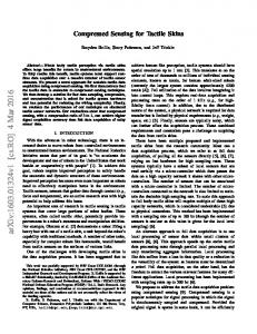
Figure 3 shows the artificial finger mounted on a gripper. The prototype finger has two PVDF sensors and two strain gauges in each layer. The final design will include sixteen strain gauges and PVDFs.
• FA I - Meissners corpuscle: These receptors provide information on texture and normal forces. They respond to stimuli in 8-64Hz range. • FA II - Pacinian corpuscle: These receptors are stimulated by vibrations. They act as event detectors. They respond to stimuli in 64-400Hz. From the biology of human fingers, we learn that a robotic finger needs two types of sensors, one that responds to stretch and another one that can respond to vibrations. The frequency response of these sensors can be limited to a maximum of 400Hz.
3.2
Artificial Tactile sensors
Our artificial finger is based on original work by Hosada, Tada and Asada[Hosoda, 2004].
Outer core (Epidermis) PVDF
Soft inner core (Dermis)
Hard back (Bone) Strain Gauge
Figure 2: Finger with embedded strain gauges and and PVDFs in two layers The finger consists of strain gauges and PVDFs embedded in a silicone finger. The strain gauges are equivalent to slow adapting mechanoreceptors. These sensors provide a change of resistance proportional to the strain applied to them i.e. they respond to lateral stretch. The PVDFs are equivalent to fast adapting mechanoreceptors. These sensors provide an electrical charge in response to the applied pressure. PVDFs are piezoelectric in nature, and are stimulated by vibrations. Figure 2 is an illustration of the artificial finger. The sensors are randomly distributed in two layers. The outer layer is harder than the inner layer. The harder outer layer allows the finger to have a less tacky surface while the soft inner layer allows the finger to conform to the object in contact. The back of the finger is made from hard material to provide structural support.
Figure 3: The artificial finger mounted on a Robotis 9 degree of freedom gripper Placing sensors randomly in the finger has several advantages. Random placement in the silicone allows the finger to sense forces in multiple direction. While the basic sensing elements of the finger respond to stimuli only in one direction, as a whole the finger can respond to forces in multiple directions. This is similar to human fingers, where some afferents respond strongly to a preferred direction of force[Birznieks et al., 2001]. Another advantage of random placement is ease of manufacture. One may argue particular arrangements might be more favourable. However precise placement and modelling of such arrangements may be very difficult and costly. Random arrangement, which relies on machine learning algorithms to map the signals to meaningful data provide rich and robust tactile perception.
4
Learning Algorithm
In this section a learning algorithm is proposed to distinguish between different textures. Different surfaces stimulate the sensors differently. A surface which has patterns that are closer together will stimulate the sensors at a higher frequency than a surface with sparse patterns. In humans, the mechanoreceptor thought to be responsible for texture classification are Meissner’s corpuscles[Russell, 1990]. These receptors respond to the rate of change of the stimulus. This makes the frequency domain a natural choice for analysis. By studying the frequency response of the sensors, the algorithm should
Australasian Conference on Robotics and Automation (ACRA), December 2-4, 2009, Sydney, Australia
be able to successfully distinguish between different textures.
4.1
Feature Extraction
The first step in the feature extraction process is to segment the signals from the sensors into the regions where the sensor is in contact with the surface. In these experiments, this step is carried out manually. Each segment is then transferred to the frequency domain using Fast Fourier Transform. The Fourier coefficients are used as features for the classification. Frequency Spectrum 4000
Algorithm 1 Peak Detection Algorithm peaks ← [] regions ← n equal divisions of frequency spectrum currentRegion ← [] repeat currentRegion ← region with the highest energy if isContiguous(currentRegion) then peaks ← updateP eak(currentRegion) else peaks ← create newP eak(currentRegion) end if regions ← remove currentRegion until desired number of peaks found
Magnitude
4.2
0
5
10
15
20
25
30
35
40
45
50
Frequency (Hz)
Figure 4: Frequency response of a PVDF sensor when rubbed across a textured surface The classification algorithm works by looking at the first two major components of the Fourier transform. Figure 4 shows a typical frequency response for a PVDF sensor, when stimulated by a particular textured surface. If the algorithm is to pick two major components from the raw data, both points will lie in the vicinity of the first peak. It will be more meaningful to pick the high level peaks as features. An algorithm has been devised to extract these peaks. Algorithm 1 is a procedure to detect the peaks in the frequency response. The peak detection algorithm divides the frequency spectrum into n equal regions. The choice of n depends on the resolution of the frequencies of interest. The algorithm goes into a loop until it finds the desired number of peaks. In each iteration of the loop, the algorithm extracts the region with the highest energy, then it checks if the current region is contiguous with any existing peaks. If any such peak is found, the algorithm extends the boundaries of that peak to include the current peak. If the region is not contiguous with any peak, a new peak is created. At the end of the loop, the current region is removed from the list of regions to be considered and the loop is repeated. Figure 4 shows two peaks being detected by the algorithm. The peak frequencies are marked in red. The boundaries of the peak start from the green vertical line and extend to the blue vertical line.
Naive Bayes Learner
All robots are prone to wear and tear. Hence it is crucial to choose an algorithm that can be trained with a small number of training data. The naive Bayes classifier is one algorithm which meets this criterion. In particular, the assumption of independence between class features means that the model parameters for each feature can be treated as a one dimensional distribution. The naive Bayes learner takes as input two frequencies for each sensor i.e. one frequency for each peak detected. The value of frequency for each peak is determined by the Fourier coefficient with the highest magnitude which is contained in that peak’s region.
5
Experimental Setup
The testing environment consists of a Denso robotic arm, an ATI force torque sensor, the robotic finger, a data acquisition unit. We report on experiments, using ten artificial textures, intended to calibrate the learning method. Experiments in progress use a variety of natural textures.
5.1
Data Acquisition
Acquisition of the data involves conditioning of the signals provided by the transducers to a format that can be digitised. The signals produced by the strain gauges and the PVDFs have very small magnitudes. The sensors are mounted on a robotic arm, which produces a significant amount of electromagnetic interference. These factors make it necessary to design and implement signal conditioning units that can amplify the small signals and yet reduce the noise from the interference.
Figure 5 shows the circuit diagram to convert the signals of the PVDF sensors. It works in two stages. The first stage converts the charges produced by PVDFs into a voltage, using a differential amplifier. This helps in reducing noise by common mode rejection. The second stage has two roles. The first, and most important role
Australasian Conference on Robotics and Automation (ACRA), December 2-4, 2009, Sydney, Australia
5.2 4M7
B
56K 56K
33K
C
PVDF
Output
6n8 4M7 56K 560K
Differential Amplifier
Buffering Stage
Filtering Stage
Figure 5: PVDF amplifier
Textures
This experiment is designed to validate the operation of the artificial finger. Textures with known surface properties are selected to ensure that the method produces the expected results. These textures are also used in neurophysiological experiments on tactile sensing. The textures are made of ridges placed a fixed distance apart. Different textures are produced by changing the distance between two ridges (i.e. the pitch). Grating 1 has a pitch of 2mm, an increase in grating number increases the pitch by 0.1mm, reaching a pitch of 3mm for grating 10. The height of the ridge is same across all textures. Figure 7 shows an illustration of the texture grating plates.
is to buffer the voltage produced by the fist stage. The buffering isolates the signals from the rest of the system, such as the analog to digital convertors. This helps to keep the noise levels low. The second role is to provide further amplification. In the final stage the signals are passed through a low pass filter. This is required to avoid aliasing in the digitisation process. (a) Grating 1, with 2mm dis- (b) Grating 10, with 3mm distance between ridges. tance between ridges. 10 K
4 2
1
Figure 7: Illustration of texture grating plates
5M6
D
1
3
10 K
1
10 K Current Source
8
9
10 K
1
10 K
0
C
Strain Gauge
33 K
Output 6n8
5M6
6
10 K
B
7
10 K 5
Sense Resistor
10 K
10 K
Anderson Loop
Our system is also able to learn to classify natural surfaces with complex textures including carpet, dishwashing sponge, a piece of wood, a tile with smooth surface, a tile with textured surface, two flooring vinyls with different surface textures. Analysis of these results is in progress and is currently being reviewed for publication[Jamali and Sammut, 2010].
Filtering Stage
5.3 Figure 6: Anderson Loop
Figure 6 Shows the signal conditioning unit for the strain gauges. Traditionally, strain gauges are conditioned using Wheatstone bridge. The main problem with the Wheatstone bridge is that it suffers from a large drift over time. For this project, an Anderson loop[Anderson, 1998] was realised. The signal provided by the Anderson loop are more superior and the drift is significantly smaller. The Anderson loop works by sending a fixed current through the strain gauge, which also passes through a reference resistor. The difference between the voltage across the strain gauge, and the voltage across the sense resistor is proportional to the value of strain on the gauge. Once again in the final stage the signals are filtered to avoid aliasing during the digitisation process.
The Learning Task
The learning task is to differentiate between ten different textures using signals from the developed fingers. Figure 8 illustrates the setup for data collection. The finger is attached to the Denso arm. The textured plate is mounted on the force torque sensor. The force torque sensor is used to monitor the total force applied to the surface. The robot drags the finger across each textured plate at a constant speed. Each run starts with the finger being positioned above starting point. The finger does not make any contact with the surface. Then the finger is moved to make contact with the surface and reach a total force of approximately 1N. With the force being kept constant, the finger moves towards the end point. The traversed path is a straight line perpendicular to the ridges. Once the end point is reached, the finger is lifted and taken back to the starting position. There is a slight delay between two runs to make sure all of the sensors have reached their idle state.
Australasian Conference on Robotics and Automation (ACRA), December 2-4, 2009, Sydney, Australia
Denso Arm
Silicone Finger
Grating plate
ATI Force/Torque Sensor
Figure 8: Experimental Setup Throughout the experiment, the total force applied to the surface of each texture and the distance between the starting point and the end point across all ten grating plates is kept constant. This procedure is repeated fifty times for each texture.
6
Results
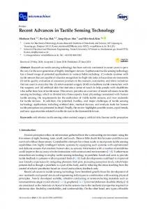
Figure 9 shows the output for the PVDF sensor when the finger is rubbed on grating 1 and grating 10. The sensor shows different frequencies of stimulation to different textures. Figure 10 shows a plot of the frequency response for all ten textures. The frequency plot shows distinct frequencies for each texture. The first two major components of each of the eight sensors were extracted using the peak detection algorithm described in Section 4. A naive Bayes learner was trained with fifty samples for each texture. The learner was capable of predicting textures with an accuracy of 99% using 10-fold cross-validation. Preliminary results on the natural surfaces achieve an accuracy of 81.7%. However further analysis is required to verify the results on natural surfaces. A simple learner was devised to evaluate the effectiveness of the method. The learner uses average amplitude over a fixed window for each channel. The richer the texture, the higher is the rate of vibration in the signal. This information can be encapsulated in the average amplitude of the signal. Each trial run is divided into three equal parts - initial contact region, middle region and lift off region. The fixed window was taken from the middle region. This ensures that the feature is not affected by the variations induced by the initial contact and lift off. The width of the window was chosen to be the average length of the middle region of all trials. A naive Bayes learner produced predictions with an accuracy of 94.6% with 10-fold cross-validation. The method based on the frequency features shows
improvement over the simple method. However a comparison of the confusion matrices shows that the method based on frequency features is much better. Table 1 shows the confusion matrix for the frequency based learning method. It can be noticed that the misclassified textures are only one grating apart from the original. Looking at the confusion matrix for the simple method (Table 2), it can be seen that the misclassifications are more scattered. For example, grating #10 textures have been misclassified as grating #1 textures. The misclassifications are further apart from the original texture.
7
Conclusion and future work
The work presented here successfully distinguishes between ten different textures using the Fourier coefficients. The novelty of work lies in the application of machine learning to tactile sensors. It has been demonstrated that with only fifty training samples, a learning algorithm can be trained to make accurate predictions. We have presented a comparison with a simpler time domain method and shown that our method produces more accurate and robust predictions. The learning algorithm uses the naive Bayes classifier for learning and classification. Naive Bayes is a probabilistic learner, where all the features are assumed to be independent. An advantage of this type of learner is that if one of the sensors fails during run time, the learner can still make accurate predictions. New experiments on irregular textures are currently being conducted. Preliminary results show that the algorithm is capable of accurately classifying these surfaces. The Fourier transform does not provide information on how the frequency content changes over time. This will be of importance for surfaces with irregular texture. The change in frequency over time can provide better information to distinguish such textures. To this end, application of Short Term Fourier Transform and Wavelet transforms may be studied.
Acknowledgements This project has been funded by the ARC Centre of Excellence for Autonomous System and the ARC/NH&MRC Thinking Systems project. We thank Professor John Morley, Raymond Sheh, Ashley Butterworth and John Zaitseff for their assistance
Australasian Conference on Robotics and Automation (ACRA), December 2-4, 2009, Sydney, Australia
Table 1: Confusion matrix for naive Bayes learner with frequency components as feature G1 G2 G3 G4 G5 G6 G7 G8 G9 G10 Class 50 0 0 0 0 0 0 0 0 0 G1 0 50 0 0 0 0 0 0 0 0 G2 0 0 50 0 0 0 0 0 0 0 G3 0 0 0 50 0 0 0 0 0 0 G4 0 0 0 0 50 0 0 0 0 0 G5 0 0 0 0 0 49 1 0 0 0 G6 0 0 0 0 0 1 49 0 0 0 G7 0 0 0 0 0 0 1 49 0 0 G8 0 0 0 0 0 0 0 2 48 0 G9 0 0 0 0 0 0 0 0 0 50 G10
Table 2: Confusion matrix for naive Bayes learner with average amplitude in a fixed window of time as feature G1 G2 G3 G4 G5 G6 G7 G8 G9 G10 Class 50 0 0 0 0 0 0 0 0 0 G1 0 50 0 0 0 0 0 0 0 0 G2 0 0 50 0 0 0 0 0 0 0 G3 0 4 0 46 0 0 0 0 0 0 G4 1 0 0 0 49 0 0 0 0 0 G5 0 0 0 0 0 50 0 0 0 0 G6 0 0 6 0 0 0 44 0 0 0 G7 0 0 0 2 0 3 0 45 0 0 G8 0 0 4 0 0 0 0 0 46 0 G9 4 0 0 0 3 0 0 0 0 43 G10
Grating 1 (PVDF signal) 4
Output (Volts)
3 2 1 0 −1 −2 −3
0
0.5
1
1.5
2
2.5
3
3.5
4
4.5
3
3.5
4
4.5
Grating 10 (PVDF Signal) 3
Output (Volts)
2 1 0 −1 −2 −3
0
0.5
1
1.5
2
2.5
Time (Seconds)
Figure 9: Grating 1 vs Grating 10. Note the difference in frequency of the signals for different textures.
Australasian Conference on Robotics and Automation (ACRA), December 2-4, 2009, Sydney, Australia
Grating 1 5
10
15
20
25
30
35
40
45
50
5
10
15
20
25
30
35
40
45
50
5
10
15
20
25
30
35
40
45
50
5
10
15
20
25
30
35
40
45
50
5
10
15
20
25
30
35
40
45
50
5
10
15
20
25
30
35
40
45
50
5
10
15
20
25
30
35
40
45
50
5
10
15
20
25
30
35
40
45
50
5
10
15
20
25
30
35
40
45
50
5
10
15
20
25
30
35
40
45
50
Grating 2
Grating 3
Grating 4
Grating 5
Grating 6
Grating 7
Grating 8
Grating 9
Grating 10
Frequency (Hz)
Figure 10: Frequency response for all ten grating plates. Note the obvious difference in frequency response between different textures.
References [Anderson, 1998] K.F. Anderson. Nasa’s anderson loop. Instrumentation & Measurement Magazine, IEEE, 1(1):5–15, 30, Mar 1998. [Birznieks et al., 2001] Ingvars Birznieks, Per Jnmalm, Antony W. Goodwin, and Roland S. Johansson. Encoding of direction of fingertip forces by human tactile afferents. Journal of Neuroscience, 21(20):8222–8237, 2001. [Brooks et al., 2004] Rodney Brooks, Lijin Aryananda, Aaron Edsinger, Paul Fitzpartick, Charles Kemp, Una-May O’Reilly, Eduardo Torres-Jara, Paulina Varshavskaya, and Jeff Weber. Sensing and manipulating built-for-human environments. International Journal of Humanoid Robotics, 1(1):1–28, 2004. [Danisch and Reimer, 1999] L. A. Danisch and E. M. Reimer. World patent of canadian space agency. PCT, Wo. 99, #04234, 1999. [Engel et al., 2004] Jonathan Engel, Jack Chen, Zhifang Fan, and Chang Liu. Polymer micromachined multimodal tactile sensors. Sensors and Actuators, A: Physical, 117(1):50–61, 2004. [Fujimoto et al., 2003] I. Fujimoto, Y. Yamada, T. Morizono, Y. Umetani, and T. Maeno. Development of artificial finger skin to detect incipient slip for realization of static friction sensation. In Multisensor
Fusion and Integration for Intelligent Systems, pages 15 – 20, Tokyo, Japan, 2003//. [Hellard and Russel, 2002] Greg Hellard and R. Andrew Russel. A robust, sensitive and economical tactile sensor for a robotic manipulator. In Proceedings of Australisian Conference on Robotics and Automation, pages 100–104, Nov 2002. [Hosoda et al., 2006] Koh Hosoda, Yasunori Tada, and Minoru Asada. Anthropomorphic robotic soft fingertip with randomly distributed receptors. Robotics and Autonomous Systems, 54:104–109, 2006. [Hosoda, 2004] Koh Hosoda. Robot finger design for developmental tactile interaction - anthropomorphic robotic soft fingertip with randomly distributed receptors. In Embodied Artificial intelligence, Fumyia Iida et al. Eds, pages 2325–2330. Springer-Verlag, 2004. [Howe, 1994] Robert D. Howe. Tactile sensing and control of robotic manipulation. Journal of Advanced Robotics, 8(3):245–261, 1994. [Jamali and Sammut, 2010] Nawid Jamali and Claude Sammut. Material classification by tactile sensing using surface textures. In IEEE International Conference on Robotics and Automation, ICRA, 2010. [Kim et al., 2004] Ji Kyoung Kim, Jae Woo Wee, and Chong Ho Lee. Sensor fusion system for improving the recognition of 3d object. 2004 IEEE Conference
Australasian Conference on Robotics and Automation (ACRA), December 2-4, 2009, Sydney, Australia
on Cybernetics and Intelligent Systems, pages 1206 – 1211, 2004. [Ohka et al., 2004] M. Ohka, Y. Mitsuya, Y. Matsunaga, and S. Takeuchi. Sensing characteristics of an optical three-axis tactile sensor under combined loading. Robotica, 22:213 – 21, 2004. [Ohka et al., 2005] M. Ohka, T. Kawamura, T. Itahashi, J. Takayanagi, T. Miyaoka, and Y. Mitsuya. A tactile recognition system mimicking human mechanism for recognizing surface roughness. JSME International Journal, Series C (Mechanical Systems, Machine Elements and Manufacturing), 48(2):278 – 85, 2005. [Ohmura et al., 2006] Yoshiyuki Ohmura, Yasuo Kuniyoshi, and Akihiko Nagakubo. Conformable and scalable tactile sensor skin for curved surfaces. In Proceedings of IEEE International Conference on Robotics and Automation, pages 1348–1353, May 2006. [Papakostas et al., 2002] Thomas V. Papakostas, Julian Lima, and Mark Lowe. A large area force sensor for smart skin applications. In Proceedings of the IEEE Sensors Conference, volume 2, pages 1620–162, Jun 2002. [Russell, 1990] R. Andrew Russell. Robot Tactile Sensing. Prentice Hall, 1990. [Tada et al., 2004] Yasunori Tada, Koh Hosoda, and Minoru Asada. Sensing ability of anthropomorphic fingertip with multi-modal sensors. In Proceedings of 8th Conference on Intelligent Autonomous Systems, pages 1005 – 1012, 2004. [Tada et al., 2005] Y. Tada, K. Hosoda, and M. Asada. Learn to grasp utilizing anthropomorphic fingertips together with a vision sensor. 2005 IEEE/RSJ International Conference on Intelligent Robots and Systems, pages 3323 – 8, 2005//. [Taddeucci et al., 1997] D. Taddeucci, C. Laschi, R. Lazzarini, R. Magni, P. Dario, and A. Starita. An approach to integrated tactile perception. Proceedings. 1997 IEEE International Conference on Robotics and Automation (Cat. No.97CH35992), vol.4:3100 – 5, 1997//. [Torres-Jara et al., 2006] Eduardo Torres-Jara, Iuliu Vasilescu, and Raul Coral. A soft touch: Compliant tactile sensors for sensitive manipulation. Technical report, Massachusetts Institute of Technology, Mar 2006.