Keywords: Artificial Neural Networks (ANN), p-q theory, (SAPF), Harmonics, Total ... permanent power quality problem introduced by this Current harmonics ...
MultiCraft
INTERNATIONAL JOURNAL OF ENGINEERING, SCIENCE AND TECHNOLOGY www.ijest-ng.com
International Journal of Engineering, Science and Technology Vol. 2, No. 5, 2010, pp. 258-267
© 2010 MultiCraft Limited. All rights reserved
The harmonics detection method based on neural network applied to harmonics compensation Rachid Dehini1*, Abdesselam Bassou2, Brahim Ferdi3 1*
Faculty of the Sciences and Technology, Bechar University, B.P 417 Bechar (08000), ALGERIA Faculty of the Sciences and Technology, Bechar University, B.P 417 Bechar (08000), ALGERIA 3 Faculty of the Sciences and Technology, Bechar University, B.P 417 Bechar (08000), ALGERIA e-mail: dehinirachid@ yahoo.fr ; Tel + 213-049-90-24, Fax.+049-81-52-44 2
Abstract Several different methods have been used to sense load currents and extract its harmonic component in order to produce a reference current in shunt active power filters (SAPF), and to contribute significantly in determining the SAPF performance. Consequently, many structures based on artificial neural network (ANN) have been developed in the literature, The most significant have used at least two Adaline networks for introducing a controller which serves to keep the terminal capacitor voltage stable. This paper presents a novel method and design that utilises one Adaline network. The latter combines both the strategies for extracting the reference currents and controlling DC link voltage which ensure suitable transit of powers to supply the inverter. To investigate the performance of this identification method, the study has been accomplished using simulation with MATLAB Simulink Power System Toolbox. The simulation study results of this novel technique compared to other similar methods are found quite satisfactory by assuring good filtering characteristics and high system stability. Keywords: Artificial Neural Networks (ANN), p-q theory, (SAPF), Harmonics, Total Harmonic Distortion. 1. Introduction Due to the proliferation of power electronic equipment and nonlinear loads in power distribution systems, the problem of harmonic contamination and treatment take on great significance .These harmonics interfere with sensitive electronic equipment and cause undesired power losses in electrical equipment (Youssef, 2001; Benachaiba, 2007). In order to solve and regulate the permanent power quality problem introduced by this Current harmonics generated by nonlinear loads such as switching power factor correction converter, converter for variable speed AC motor drives and HVDC systems, the passive filters have been used; which are simple and low cost. However, the use of passive filter has many disadvantages, such as large size, tuning and risk of resonance problems (Rahmani, 2006; Ping, 2009). Lately, owing to the rapid improvement in power semiconductor device technology that makes high-speed, high-power switching devices such as power MOSFETs, MCTs, IGBTs , IGCTS , IEGTs etc. usable for the harmonic compensation modern power electronic technology, Active power filter (APF) have been considered as an effective solution for this issue, which been widely used ( Matthew, 2004). One of the most popular active filters is SAPF (Rahmani, 2006; Akagi, 2003; Rafiei, 2006). SAPF have been researched, developed and have gradually been recognized as a workable solution to the problems created by non-linear loads. The functioning of shunt active filter is to sense the load currents and extracts the harmonic component of the load current to produce a reference current i c* , a block diagram of the system is illustrated in Fig. 1. The reference current consists of the harmonic components of the load current which the active filter must supply. This reference current is fed through a controller and then the switching signal is generated to switch the power switching devices of the active filter so that the active filter will indeed produce the harmonics required by the load. Finally, the AC supply will only need to provide the fundamental component for the load, resulting in a low harmonic sinusoidal supply (Dai, 2007; Abdelkhalek, 2008a; Ramos-Carranza et al., 2008).Generally, effectiveness of SAPF
259
Dehini et al./ International Journal of Engineering, Science and Technology, Vol. 2, No. 5, 2010, pp. 258-267
depends on three design criteria: (i) design of power inverter; (ii) use of current controller’s types (iii) methods used to obtain the reference current. The presented work was oriented mostly on the latter criterion.
3 phase AC Supply
isa , isb , isc
v sa , v sb , v sc
isa isb i sc
Current Detetction
iia , iib , iic
ica icb icc
Control Circuit Sa
Lf Lf Lf
iia iib iic
iLa iLb
Ls
Ls
Vc
Sb
Sc Vdc
iLc
Ls RL LL
Figure 1. Schematic diagram of shunt APF In order to determine harmonic and reactive component of load current, reference source current generation is needed. Thus, reference filter current can be obtained when it is subtracted from total load current. For better filter performance, generation of reference source current should be done properly. For this purpose, several methods such as pq-theory, dq-transformation, multiplication with sine function and Fourier transform have been introduced in literature (Soliman, 1997; Tahri, 2005; Hui, 2006; Abdelkhalek, 2008c). Recently, some methods based on artificial intelligence have been applied In order to improve processing detecting time of harmonic current. The past decade has seen a dramatic increase in interest Artificial Neural Networks (ANNs) which is characterized by its learning ability and high speed recognition but simple structure, the (ANNs) have been applied in many uses in the power electronic part of both machinery (Ahmed, 2004) and filters devices (Dai, 2008; Nguyen, 2008; Pecharanin, 1994; Rukonuzzaman, 2001) where they have justified their effectiveness. The results obtained with ANNs are often better than those of traditional methods. Indeed, as a result of their capacities to optimize simultaneously their weights and biases in an on-line training process, they are able to adapt themselves to any system. In this paper, a detection method using artificial neural network ANN is presented which can be utilized in both harmonic current detection from distorted wave and DC link control voltage. This method can precisely obtain the reference current of each phase. The learning rate can be regulated in a wide range with little affection on the performance with a simple structure and theory (Yongtao, 2008). The performances of the Neural Method are evaluated under simulation and are compared with p-q theory. 2. Reference Source Current Generation The concept of instantaneous reactive power theory (p-q theory) method basically consists of a variable transformation from the a, b, c reference frame of the instantaneous power, voltage and current signals to the α − β reference frame (Abdelkhalek, 2008c). The instantaneous values of voltages and currents in the α − β coordinates can be obtained from the following equations:
260
Dehini et al./ International Journal of Engineering, Science and Technology, Vol. 2, No. 5, 2010, pp. 258-267
⎡ ⎢ ⎢ ⎣
⎡ ⎤ ⎢ α ⎥ = [A] ⎢ ⎥ ⎢ β⎦ ⎢⎣
⎡i ⎤ v ⎤⎥ ⎡ ⎤ iα ⎥ = [A] ⎢⎢ ⎥⎥ ⎢ ⎥ , v⎥ ⎢ ⎥ i ⎢ ⎥ i β⎦ ⎣ ⎢⎣i ⎥⎦ v ⎥⎦
v v
a
a
b
b
c
c
(1)
where A is the transformation matrix and is equal to: (2)
−1 ⎤ ⎡1 − 1 2 2 ⎥ ⎢ [A] = ⎢ 3 − 3 ⎥ ⎢⎣0 2 2 ⎥⎦ This transformation is valid if and only if
v (t ) + v (t ) + v (t ) = 0 and also if the voltages are balanced and sinusoidal. The a
b
c
instantaneous active and reactive powers in the α − β coordinates are calculated with the following expressions:
p (t ) =
v α (t )i α (t ) + v β (t )i β (t ) q (t ) = v α (t )i β (t ) − v β (t )i α (t )
(3) (4)
The values of p and q can be expressed From Eqs.(3) and (4) in terms of the dc components plus the ac components, that is:
p= p+~ p q = q + q~
(5) (6)
where:
p : is the dc component of the instantaneous power p, and is related to the conventional fundamental active current. ~ p : is the ac component of the instantaneous power p, it does not have average value, and is related to the harmonic currents caused by the ac component of the instantaneous real power.
q : is the dc component of the imaginary instantaneous power q, and is related to the reactive power generated by the fundamental components of voltages and currents.
q~ : is the ac component of the instantaneous imaginary power q, and is related to the harmonic currents caused by the ac component of instantaneous reactive power. In order to compensate reactive power and current harmonics generated by nonlinear loads, the reference signal of the shunt active power filter must include the values of ~ p and q~ (Abdelkhalek, 2008a). In this case, the reference currents required by the SAPF are calculated with the following expression:
~ i α ⎤⎥ = 1 ⎡⎢vα vβ ⎤⎥ ⎡⎢ P ⎤⎥ ⎥⎢~ ⎥ ⎢ ⎥ i β ⎥⎦ vα + vβ ⎢⎣vβ −vα ⎥⎦ ⎢⎣q ⎥⎦
⎡ ⎢ ⎢ ⎢⎣
* c
* c
L
2
2
L
The final compensating currents components in a, b, c reference frame are the following:
(7)
261
⎡ ⎢ ⎢ ⎢ ⎢ ⎢⎣
Dehini et al./ International Journal of Engineering, Science and Technology, Vol. 2, No. 5, 2010, pp. 258-267
i i i
⎤ ca ⎥ * ⎥ = cb ⎥ * ⎥ cc ⎥ ⎦ *
vsa , vsb , vsc
⎡ ⎢ ⎢ 2 ⎢ − 3 ⎢ ⎢ ⎢ ⎢⎣ −
1
0
1 2 1 2
3 2 3 − 2
Park Transforma tion
⎤ ⎥ ⎥ ⎥ ⎥ ⎥ ⎥ ⎥⎦
⎡ ⎢ ⎢ ⎣⎢
i i
* cα * cβ
⎤ ⎥ ⎥ ⎦⎥
(8)
vα , vβ
p
vα , vβ
isa , isb , isc
Park Transforma tion
p
) p
q
) q
p and q transforma tion
iα , iβ
q
i*ca ,i*cb ,i*cc
Reference current calculation in a-b-c
Reference current calculation in a-b-c in
i *c α , i *c β
Figure 2. Block diagram for the instantaneous active and reactive power The (SAPF) control strategy involves not only the production of currents whether to eliminate the undesired harmonics or to compensate reactive power (Abdelkhalek, 2008b), but also to recharge the capacitor value requested by VDC voltage in order to ensure suitable transit of powers to supply the inverter (Khadkikar, 2008). The storage capacity C absorbs the power fluctuations caused by the compensation of the reactive power, the presence of harmonics, and the active power control and also by the losses of the converter. The average voltage across the capacitor terminals must be kept at a constant value. The regulation of this voltage is made by absorbing or providing active power on the electrical network. The correction of this voltage must be done by adding the fundamental active current in the reference current of SPAF (Benachaiba, 2006). To realize these objectives, a controller as shown in Figure 3 is added to regulate the capacitor dc voltage of the (SAPF). In this circuit, the actual DC capacitor voltage is detected and compared with the reference value, and the error is amplified then added to the
~ p
L
, the output of high-pass filter in
Figure 2. Therefore, active power allowed into the capacitor is being changed and the dc voltage is controlled. p~ * ( t )
(PI) Controller
Figure 3. Control of DC Voltage
~ p * (t )
262
Dehini et al./ International Journal of Engineering, Science and Technology, Vol. 2, No. 5, 2010, pp. 258-267
Conventional PI Controller: The reason behind the extensive use of proportional integral controller or named simple PI controller (CPI) is its effectiveness in the control of steady-state error of a control system and also its easy implementation. However, one disadvantage of this conventional compensator is its inability to improve the transient response of the system. The conventional PI controller (Figure 4) has the form of Eq. (9), where Y is the control output which is fed to the PWM signal generator. KP and KI are the proportional and integral gains respectively, these gains depend on the system parameters. ε is the error signal, which is the difference of the injected current to the reference current. t
∫
y (t ) = K p * e(t ) + K i e(t )dt
(9)
0
Equation (1) shows that the PI controller introduces a pole in the entire feedback system, consequently, making a change in its original root locus. Analytically the pole introduces a change in the control system’s response. The effect is the reduction of steady-state error.
Kp
p * (t ) ε
Vr
Ki
Y
PWM
s DC voltage(Vdc)
CPI Controller
p (t )
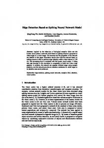
Figure 4. Control of the injected current using conventional PI controller (CPI) On the other hand, the constants KP and KI determine the stability and transient response of the system, in which, these constants rely on their universe of discourses: KP Є [KPmin, KPmax] and KI Є [KImin, KImax]. Where the values of the minimum and maximum proportional and integral constants (gains) are practically evaluated through experimentation and using some iterative techniques. This makes the design of the conventional PI controller dependent on the knowledge of the expert. When the compensator constants exceed the allowable values, the control system may come into an unstable state. After the determination of the domain of the proportional and integral constants, the tuning of the instantaneous values of the constants takes place. Depending on the value of the error signal, ε, the values of the constants adjusts formulating an adaptive control system. The constants KP and KI changes to ensure that the steady-state error of the system is reduced to minimum if not zero 3. Neural networks for Reference Source Current and DC Voltage Control In this work, the p-q theory is modeled, as depicted in Fig. 5, by an artificial neural network (ANN) made up of two hidden layers with 12 neurons each, and one output layer with 3 neurons. The logarithmic activation function is the base of the two hidden layers neurons, and linear activation function for the output layer neurons. The ANN in Fig. 5 has seven inputs ( vsa,vsb,vsc,vdc; i sa , i sb , i sc ) and three outputs ( i
* ca
,i
* cb
,i
* cc
), as observed in the p-q
theory. The model of the neurons of the hidden layers is represented in Fig.5, where each neuron has n inputs. This parameter varies in function of the chosen hidden layer, where n equals 7 if the neuron belongs to hidden layer 1, and n equals 12 if the neuron belongs to hidden layer 2. For the neurons of the output layer, n equals 12. The adaptation of the weights (W) and bias (b) in the ANN, is based, first, on the computation of the mean square error (MSE) between the outputs of the PQ technique and those of the ANN, and secondly, on the execution of ‘Levenberg-Marquardt backpropagation’ algorithm (Bouhali,2005).
263
Dehini et al./ International Journal of Engineering, Science and Technology, Vol. 2, No. 5, 2010, pp. 258-267
Hidden layer 1
Hidden layer 2
. . . . .
. . . . .
Output layer
Weights and bias adaptation
vsa,vsb,vsc,vdc i sa , i sb , i sc
Mean square error computation
i *ca , i *cb , i *cc In1 W1 . . . . Inn Wn
∑
Out
b
In1 W1 . . . . Inn Wn
∑
Out
b
Neuron with logarithmic activation function
Neuron with linear activation function
Figure 5. Neural network for (p-q theory) modeling 4. Simulation Results The performance of the proposed detection method using artificial neural network (ANN) was examined through simulations. The system model was implanted in Matlab / Simulink environment. The (SAPF) was designed to compensate harmonics caused by nonlinear loads. The system model parameters are shown in Table 1.
Table.1 system parameters Parameters Supply phase voltage U 220 V Supply frequency fs 50 Hz Filter inductor Lf 0.7 mH Dc link capacitor Cf 0.768474 mF Vdc 850V Smoothing inductor 70 μH Lsmooth A three-phase diode rectifier with an RL load was used as a harmonic producing load. The load value is (resistance was 10/3 Ω and the inductance 60 mH. or Load apparent power SL=82VA).
264
Dehini et al./ International Journal of Engineering, Science and Technology, Vol. 2, No. 5, 2010, pp. 258-267
(a) 200 0 -200
0
0.02
0.04
0.06
0.08
0.1
0.12
0.14
0.16
0.18
0.2
0.12
0.14
0.16
0.18
0.2
0.12
0.14
0.16
0.18
0.2
0.12
0.14
0.16
0.18
0.2
(b) 200 0 -200
0
0.02
0.04
0.06
0.08
0.1 (c)
200 0 -200
0
0.02
0.04
0.06
0.08
0
0.02
0.04
0.06
0.08
0.1 (d)
500 0 -500
0.1 Time (sec)
Figure 6. (a) Simulated phase-a load current waveforms, (b) Simulated phase-a reference current waveforms , (c) Simulated phase-a the supply current waveforms , (d) Simulated the supply voltage waveforms with a (p-q theory) method (a) 200 0 -200
0
0.02
0.04
0.06
0.08
0.1 (b)
0.12
0.14
0.16
0.18
0.2
0
0.02
0.04
0.06
0.08
0.1 (c)
0.12
0.14
0.16
0.18
0.2
0
0.02
0.04
0.06
0.08
0.1 (d)
0.12
0.14
0.16
0.18
0.2
0.1
0.12
0.14
0.16
0.18
0.2
200 0 -200
200 0 -200
500 0 -500
0
0.02
0.04
0.06
0.08
Time (sec)
Figure 7. (a) Simulated phase-a load current waveforms, (b) Simulated phase-a reference current waveforms , (c) Simulated phase-a the supply current waveforms , (d) Simulated the supply voltage waveforms with a (ANN) method
265
Dehini et al./ International Journal of Engineering, Science and Technology, Vol. 2, No. 5, 2010, pp. 258-267
Table 2. Harmonic supply current phase-acomponent
Harmonic supply current components Isa(n)/Isa(1) [%] n
load
5 7 11 13 17 19 23 25 29 31 35 37 41 43 47 49 THD
19.59 13.56 8.06 6.48 4.38 3.63 2.51 2.08 1.43 1.18 0.82 0.70 0.56 0.51 0.46 0.44 26.91
p-q theory 0.37 0.43 0.17 0.27 0.41 0.21 0.11 0.15 0.21 0.05 0.07 0.03 0.16 0.01 0.11 0.05 1.05
(ANN) method 0.28 0.37 0.04 0.24 0.06 0.17 0.06 0.12 0.04 0.08 0.04 0.05 0.03 0.05 0.04 0.05 0.74
Figure 8. Harmonic spectrum of supply current Phase ‘a’
900 800 700 Vdc (p-q theory) Vdc (ANN methode)
600 500 400 300 200 100 0 0
0.1
0.2 0.3 Time(sec)
0.4
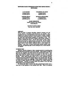
Figure. 9.DC link voltage regulation comparison between (p-q theory) and (ANN) Table 3. Performance indices, system with the two methods (ANN) (p-q theory) Case Case Rise Time
0.1488
0.08598
overshoot
0%
0%
Settling Time(s)
0.15
0.42
Steady-state Error
0.3280%
0.3301%
0.5
266
Dehini et al./ International Journal of Engineering, Science and Technology, Vol. 2, No. 5, 2010, pp. 258-267
In simulations the two different identification methods were used .Because of the (ANNs) capacities to optimize simultaneously their weights and biases in an on-line training process; this approach improves the (SAPF) performance. The filtering result can be seen in Figure 6 and 7. The deformations have now been reduced and the harmonic distortion calculated up to 2.5 kHz (THD2.5kHz) has been weakened. Although the filtering performance especially with the low order harmonics has been improved, this can be seen in Table 2, where the THD calculated up to 2.5 kHz remains less than the case of (p-q theory) approach. Figure 9 represents the controlled voltage on the borders of the condenser. We compared between the pro-posed approach (ANN) and the case of the PI controller which is incorporated in (p-q theory) as shown in Table.3. It seems clearly that the PI controller in (p-q theory) is characterized by a very low Rising Time and Settling Time (Tr is equal to 0.08598 s, Ts is equal to 0.15 s) compared to the (ANN) case (Tr is equal to 0.1488 s, Ts is equal to 0.42 s). The former case presents acceptable results at the level of DC voltage control.
5. Conclusion The work presented in this paper makes a significant contribution to the identification and control strategies in order to improve the SAPF performance. The novel approach which based on intelligent neural techniques has been proposed. The performance of the proposed ANN was verified through simulation studies with Matlab and confronted with classical technique. The complete SAPF structure has been implanted to compensate harmonics caused by nonlinear loads. At this level, comparative studies between the neural approach and; one of the most conventional techniques used to extract the harmonic component of the load current to produce reference currents; (p-q theory) have been accomplished. The achieved results can assert that all the identifying objectives of the harmonic currents can be satisfied by the approach based on neural networks. However, the (p-q theory) merit is that the latter contains integrated (PI) controller, added to regulate the capacitor dc voltage of the (SAPF). References Abdelkhalek. O, Benachaiba. C, Haidas .M, Benslimane .T. 2008a. A new technique applied to a fuzzy regulator to control the shunt active filter DC bus voltage, Journal of Information Technology and Control, Vol.37, No.3, pp. 227 – 232. Abdelkhalek. O, Benachaiba. C, Benslimane .T, Haidas .M. 2008b. A novel theory of reference harmonic current identification based on the per unit system used for the active filters, Journal of Electrical & Electronics Engineering, Vol. 8, No. 2, pp. 747757. Abdelkhalek. O, Benachaiba. C, Benslimane .T, Haidas .M. 2008c. A novel theory of reference reactive current identification based on the per unit system used for the active filters, Journal of Electrical & Electronics Engineering, Vol. 8, No. 2, pp. 759767. Ahmed .M. 2004. Sliding mode control for switched mode power supplies, PhD Thesis, Lappeenranta University of Technology, Lappeenranta, Finland, pp. 32-34. Akagi. H, Srianthumrong S and Tamai Y. 2003. Comparisons in circuit configuration and filtering performance between hybrid and pure shunt active fitters, IEEE 38th Conf on Industry Applications, Vol. 2, pp. 1195-1202. Benachaiba.C, Dib.S and Abdelkhlek O. 2006. Genetic algorithm-based self-learning fuzzy PI controller for shunt active filter, International Journal of Applied Engineering Research, Vol. 1, No. 2, pp. 203-216. Benachaiba. C, Ferdi .B. 2007. A comparative study of IEC 61000 Part 3-2 & 3-4 and IEEE 519-1992 standards in low voltage applications, International Review of Electrical Engineering, pp. 771-776. Bouhali. O, Berkouk. M, Francois .B, C. Saudemont, L.S. 2005. Solving harmonics elimination problem in voltage-controlled three phase inverter using artificial neural networks, J. Electrical Systems, Vol. 1, No. 1, pp. 47-61. Dai .W, Huang. T, Lin N. 2007. Single-phase shunt hybrid active power filter based on ANN, Proceedings of the Fourth International Conference on Fuzzy Systems and Knowledge Discovery, Vol. 2, pp. 40-44. Dai .W, Wang .Y. 2008, Active power filter of three-phase based on neural network, Proceedings of the 2008 Fourth International Conference on Natural Computation, Vol. 7, pp. 124-128. Hui.L, Guohai.L and Yue. S. 2006, A novel harmonics detection method based on wavelet algorithm for active power filter, Proceedings of the 6th World Congress on Intelligent Control and Automation, June 21 - 23, 2006, Dalian, China. Khadkikar.V.,Chandra.A., Singh. B.N. 2007, Generalised single-phase p-q theory for active power filtering: simulation and DSPbased experimental investigation, IET Power Electronics, doi: 10.1049/iet-pel:20070375. Matthew.A. G. 2004. A comparative analysis of proportional-integral compensated and sliding mode compensated shunt active power filters, M.Sc. Thesis, Department of Electrical and Computer Engineering, Mississippi State University. Nguyen. N. K, Ould Abdeslam. D, Wira. P, Flieller. D, Mercklé J. 2008, Artificial neural networks for harmonic currents identification in active power filtering schemes, Industrial Electronics, 2008. IECON 2008. 34th Annual Conference of IEEE, Orlando, Florida, pp. 2696 – 2701. Pecharanin. N,Sone. M., Mitsui .H .1994, An application of neural network for harmonic detection in active filter, ICNN 1994, pp 3756-3760.
267
Dehini et al./ International Journal of Engineering, Science and Technology, Vol. 2, No. 5, 2010, pp. 258-267
Ping W., Zhixiong Z., Houquan C. 2009. A DSP-based active power filter for three-phase power distribution systems, 2009 International Conference on Computer Engineering and Technology, 978-0-7695-3521-0/09, IEEE doi 10.1109/iccet.140 Rafiei . M.2006. Verification of global optimality of the OFC active power filters by means of genetic algorithms, Proc. WSEAS Int. Conf. on Systems, Vouliagmeni, Athens, Greece, Jul. 10-12, pp. 559-564. Rahmani. S, Al-Haddad. K, Fnaiech. F. 2006. A three-phase shunt active power filter for damping of harmonic propagation in power distribution systems, IEEE ISIE 2006, July 9-12, Montreal, Quebec, Canada, pp. 1760-1764. Ramos-Carranza, H.A., Medina, A., Chang, G.W., 2008. Real-time shunt active power filter compensation, IEEE Transactions on Power Delivery, Vol. 23, No. 4, pp. 2623 – 2625. Rukonuzzaman. M, Nakaoka. M. 2001. Adaptive neural network based harmonic current compensation in active power filter, Neural Networks, Vol. 3, pp. 2281 – 2286. Soliman, S. A, El-Naggar. K,and Al-Kandari, 1997. Kalman filtering based algorithm for low frequency power systems subharmonics identification, International Journal of Power and Energy Systems, Vol.17, No. 1, pp. 38-43.. Tahri A., Draou. A. 2005. Instantaneous active and reactive power measuring method in three phase power system, Leonardo Electronic Journal of Practices and Technologies, Vol. 4, No. 6, pp. 17-28. Yongtao, D. Wenjin, D. 2008, Harmonic and reactive power compensation with artificial neural network technology, Proceedings of the 7th World Congress on Intelligent Control and Automation, June 25 - 27, Chongqing, China. Youssef. K. 2001, Industrial power quality problems electricity distribution, IEE Conf. Pub1. No. 482, Vo1.2. pp. 18-21.
Biographical notes R.Dehini : received the stage license degree in electrical & engineering from the national high school of technical teachings (ENSET) ALGERIA. Currently, He is working toward the Doctorate degree. His interests are in electrical power quality. A. Bassou : received the state engineer degree in Electronic Engineering in 1997 from the University of Abou Bekr Belkaïd de (Tlemencen-Algeria) and the M.S. degree in 2000 from University of Djillali Liabes (Sidi Bel Abbes–Algeria). In 2006 he received the doctorate degree from University of Djillali Liabes (Sidi Bel Abbes, Algeria), and currently holding the post of Assistant Professor. His current research and teaching interests are in the areas of Artificial Neural Networks, telecommunication and signal processing. Presently he is supervising doctoral students working in the field of telecommunication and Artificial Neural Networks. B. Ferdi :received the stage engineer degree in electrical & engineering from the University of Boumerdes (INELEC), in 1991 and the MS degree in 2008 from Bechar University ALGERIA. Currently, He is working toward the Doctorate degree. His areas of interest are hybrid active power filters, applications of power electronics, and power quality improvement.
Received July 2010 Accepted August 2010 Final acceptance in revised form August 2010