*School of Electrical Engineering and Telecom, UNSW, Sydney. Abstract. Due to the ... very attractive for many high performance automotive applications.
Australasian Universities Power Engineering Conference (AUPEC 2004) 26-29 September 2004, Brisbane, Australia
THE VECTOR CONTROL TECHNIQUES FOR LOW VOLTAGE IPM MACHINE IN 42V SYSTEM Rukmi Dutta* and M.F. Rahman* *School of Electrical Engineering and Telecom, UNSW, Sydney
Abstract Due to the decreasing level of fuel and concern for clean environment, the automotive industry is being pushed for manufacturing more and more fuel-economic and environment friendly cars. As a result many mechanically driven auxiliaries are being replaced by electrical ones. The passengers’ comforts and safety are also increasing with time. All these are leading us to an elevated on board power demand. In order to cope with the higher demands, present dc bus voltage level of 12 V need to be increased to 42 V. Considering efficiency and size, the IPM(Interior type Permanent Magnet) machines are attracting attentions from research community for variety of automotive applicationsfrom vehicle propulsion to integrated starter alternator (ISA). Although the design of IPM machine for extended speed operation itself poses many technical difficulties, the success of the complete drive system depends on the availability of a control algorithm that can extract the most efficient performance capability from the machine. Due to the practical constraint of some applications such as ISA, the IPM machines can have characteristic current less than its peak current rating. In this paper an investigation has been made to find out the most suitable control algorithm for a low voltage IPM machine of 42 V system that have characteristic current less than its peak rated current 1.
INTRODUCTION
In order to cope with the increasing on board power demand of future generation automobiles, the present voltage level of 12V is proposed to increase up to 42V. The IPM (Interior type Permanent Magnet) machine are very attractive for many high performance automotive applications. Previous research work has revealed that ratio of magnetic flux linkage to d-axis inductance ( ψ PM ) affects the power capability, range of constant Lds
power and flux weakening performance [1]. Since the comparative value of above ratio to the system peak current rating, is the crucial factor of IPM machine characteristic, it can be termed as characteristic current of the IPM machine. When the characteristic current is equal to the system peak current, we have optimal condition for flux weakening. But a new class of IPM machines is emerging for special applications in Electric Vehicle, Hybrid or Mild hybrid vehicles, in which the characteristic current is less than its peak system current ).In this type of machine, although rating ( ψ P M L ds
< I sm
constant power range is limited to a finite speed range, the field weakening operation is available theoretically
up to infinite speed [2]. For a 42 V DC-bus system, the IPM machine may have as low as 20 V rated voltage with high performance capability for a wider field weakening range. Such machines are designed in pancake shape due to space constraint in the automobile architecture. Since these machines are designed for very high speed operation, there should be sufficient iron bridge between magnet poles for mechanical integrity. Wider Iron Bridge results in higher leakage flux, where as smaller rated voltage means lower magnetic flux linkage. As a result, these IPM machines have characteristic current less than system peak rated current. In this paper an investigation has been made for a suitable control technique of a low voltage IPM machine that have characteristic current ( ψ P M ) less Lds
than its peak rated current. 2.
IPM MACHINE MODEL
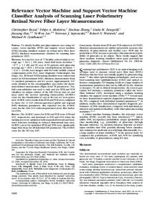
The IPM machine is commonly analysed using two axes theory. The d-axis is defined in the direction of the rotor permanent magnet flux linkage phasor so that the orthogonal q-axis is aligned in with the open circuit back EMF phasor. The equivalent circuit for IPM machine is
shown in fig. 1. The d-q axes voltage and flux linkages are expressed as, dψ ds (1) v = R i + −ωψ ds
s ds
v qs = R s iqs + ψ
ds
ψ
qs
qs
dt
dψ qs dt
(2)
+ ωψ ds
= ( L ld + L m d ) i d s + ψ
PM
= L d s id s + ψ
PM
(3) (4)
= ( L lq + L m q ) iq s = L q s iq s
Where, [Ohm] Rs : Stator winding resistance [A] ids ,iqs: d and q axes currents vds, vqs: d and q axes voltages [V] [Wb] ψds, ψqs: d and q axes stator flux linkage [H] Lld,Llq: d and q axes leakage inductance [H] Lmd,Lmq: d and q axes stator inductance Lds , Lqs : d and q axis total stator inductances [H] Permanent magnet flux linkage [Wb] ψPM: ω : Synchronous speed of the machine [rad/s] The steady state equations of the machine are, (5) V d s = R s I d s − ω L qs I qs
V qs = R s I qs + ω ( Ψ P M + L ds I d s )
(6)
Lld
ids
yPM
Lmd
DC
-
wyds Rs
3.1.
Current and Voltage Constraints
The operating limits of a drive system are determined from the voltage and current constraints of the inverter and the machine. For better performance and stability of the system, the control strategy must satisfy these constraints. For an IPM drive system these constraints are given as, (7) Is = I d2s + I q2s ≤ I s m V d2s + V qs2 ≤ V sm
Vs =
(8)
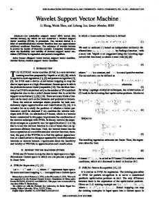
Where, Ism : Peak phase current of the machine [A] Vsm: Peak phase voltage available from the DC bus [V] In the operation below base speed, only current constraint needs to be met. The voltage constraint starts to affect the system at higher speed. The critical condition of (7) is given as a current limit circle with origin as the center in ids/iqs plane while the condition (8) is given as voltage limit ellipse with center at (- ψ PM ) , long half axis as V sm and short half axis as V s m . ω Lds ω L qs
+
Vds
CONTROL PRINCIPLES
L ds
Capital letters indicate steady state values.
Rs
3.
For a constant voltage level, there will be a series of concentric ellipse for different speeds that shrinks with increasing speed. It has been shown in [3, 4] that current and voltage constraint of an IPM drive system and its operation can be demonstrated in ids- iqs plane as shown in fig.2. A few assumptions are made for simplification of this illustration such as i) Core loss is neglected, ii) Since voltage constraint become predominate only at higher speed where stator resistive drop is negligible compared to back EMF and reactive drops, iii) The affect of magnetic saturation can be considered in machine parameters.
Llq
+
3.2.
iqs
Lmq Vqs DC
-
wyqs Fig.1. The two axes equivalent circuits
Control in Constant Torque Region
The average torque of the IPM machine at steady state operation is, 3 (9) T = p[I ψ + (L − L )I I ] e
2
qs
PM
ds
qs
qs
ds
Where, p: The number of pole pairs in the machine. Below base speed the armature current vector is controlled to produce maximum torque per ampere [5]. There are many different strategies to achieve maximum torque per ampere (MTPA) for an IPM machine. Among
them the two most common techniques are as described in [4] and [5,6]. In [5, 6] the reference torque command Te* is converted to reference command of ids* and iqs* with help of two function blocks fd (Te*) and fq (Te*) that reflects machine characteristic of MTPA directly. On the other hand in [4], the relationship between ids and iqs for MTPA control is derived as, ψ PM ψ P2 M 2 (10) id s =
2 ( L ds − L qs )
−
4 ( L qs − L ds )
+ iq s
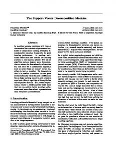
The limiting values (Idlim, Iqlim) are decided by the cross point of the MTPA trajectory and the current limit circle at point ‘A’, as shown in fig 3. Any one of the above mentioned techniques can be used to drive a low voltage IPM machine having characteristic current less than rated current with 42v DC bus-system, in MTPA control region. But in the first strategy, maximum attainable torque is slightly less than that could be achieved with the second method, because operating point of the torque command is inside the current limit circle rather than on its periphery as is the case in the second method.
i) Torque command dependent technique: The fig. 4 illustrates the need to modify the current commands generated by the MTPA torque controller at higher speed. Let us assume the reference torque command defines d and q axes currents at point “A”, on the figure. Since this point lies outside the voltage limit ellipse, the system will be unable to reach it. The actual operating point will lie within the ellipse near point “B” resulting in a lower torque of T1*. The flux weakening algorithm modifies the current commands at higher speed forcing the operating point to the left along the ellipse boundary to intersect the torque curve at point “C”. In order to reach this point, the controller limits the iqs* command to stay within the ellipse and increases the ids* command to move along the ellipse boundary to the left. For any given speed, DC bus voltage and ids*, the controller limits the iqs* to its maximum attainable value given as V sm 2 L ds 2 ψ P M 2 (11) iq s _ m ax =
(
ω L qs
) − (
) ( id s +
L ds
)
The error between the command and calculated torque adjusts the ids* command with a PI compensator, forcing the torque error to zero [6]. ii) d-axis Current Command dependent technique: In this method, the ids* and iqs* are controlled to maintain the critical condition (8) and relationship between ids and iqs is derived from the same equation as, ψ 1 V (12) i = − PM + ( sm ) 2 − ( L i ) 2 ds
Lds
ω
L ds
Where, i ≤ V s m , i .e qs ω L qs
Fig.2. Current and voltage limit in ids-iqs plane
L qs
qs qs
V ds ≤ V sm
The current vector producing the maximum torque at a given speed is the cross point of the current limit circle and the voltage limit ellipse. In this technique, the operating point moves from MTPA control point ‘A’ to flux weakening point ‘B’ in the periphery of current limit circle’ as shown in the fig 3.Now let us check the cross points of voltage limit ellipse and current limit circles of a low voltage IPM machine with characteristic current less than rated current, using relation (12). At a certain speed ω 1 , the smaller Vsm makes V s m to falls ω1
3.3.
Control in Flux-weakening region
With increasing rotor speed, the attainable ranges of machine current are limited by the ability of the DC bus voltage to accommodate the growing motor terminal voltage. Again there exist two main techniques to control the ids and iqs current in the voltage limit ellipses. Let us check both the techniques and their suitability for low voltage IPM machine in the 42 V system.
below iqsLqs in (12) leading to an imaginary number for ids. As a result, we can not have the desired cross point of current limit circles and voltage limit ellipse from (12) any more. The condition is shown in fig.5, where the point ‘P’ defines ψ P M in the ids- iqs plane. Hence, −
L ds
the d-axis current command dependent control fails in flux weakening region for low voltage IPM machine with characteristic current less than its peak rated
current after certain speed ω1. If characteristic current is less than Idlim of MTPA, d-axis current command dependent control will not work in the flux-weakening range at all.
IPM machine that has characteristic current less than the rated current. The machine parameter are given in Table 1 and taken from [7]. TABLE 1 PARAMETER OF THE IPM MACHINE
Number of Phases Number of Poles Lds Lqs ( unsaturated) ψPM Peak current constraint Characteristic current ( ψ PM )
3 12 64.97 µH 305.05 µH 6.3 mWb 327 A 96.96 A
L ds
DC Bus voltage
Fig. 3: MTPA trajectory and current limit circle
42 V
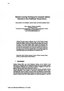
In fig.6 the current trajectory obtained from simulated model is shown in ids and iqs plan for d-axis current command dependent control technique. At 2000 r/min, field weakening control fails; hence current trajectory was swinging toward positive iqs- axis indicating saturation of current regulators. In fig.7, the current trajectory obtained from torque command dependent technique is shown. In this case, the same machine was able to rotate at 2000 r/min with flux weakening. In both cases unsaturated Lqs value was used assuming a constant parameter model. With saturation Lqs value will decrease with current. It should be noted that the voltage limit ellipses of ids-iqs plan, will be distorted in the iqs axis, if the effect of magnetic saturation is included in the parameters [7]. By expressing Lqs as a function of iqs current, the saturation of the machine can be affectively included in the machine model [8]. In [7], Lqs is expressed as B L q s = C i q s (13), for Lqs < Lqs (unsaturated), otherwise Lqs=Lqs(unsaturated).Where, C=0.0058, B= 0.605 The Lqs against iqs is shown in fig.8, and we can assume that machine will be saturated once iqs current rise above 150 A. The (12) can be modified, substituting Lqs from (13).
Fig.4. MTPA trajectory, voltage limit ellipse and torque command
4.
SIMULATION RESULTS
Both the control strategies are applied to a MatlabSimulink constant parameter model of a low voltage
ids = −
ψ PM Lds
+
1 Lds
(
V sm
ω
) 2 − ( Ciqs
( B +1) 2
)
(14)
Where iqs > 150 A. In this case too, ids will be imaginary for any iqs value in the field weakening range. Thus it can be concluded that the d-axis current command dependent vector control will not be suitable for whole range of flux-
weakening in a low voltage IPM machine that have characteristic current less than peak rated current.
Fig.5. Current and Voltage limits for a low voltage IPM machine with characteristic current less than rated current. Fig.7. Simulation result of stator current trajectory in torque command dependent control
-4
3.2
x 10
3
2.8
Lqs in H
2.6
2.4
2.2
Fig.6. Simulation results of stator current trajectory showing failure of field control in d-axis current command
2
1.8
1.6 0
50
100
150 200 Iqs current in A
250
Fig.8. Variation of Lqs with iqs current
300
350
5.
CONCLUSION
The difficulties with two of the common control techniques for a low voltage IPM machine having characteristic current less than rated current, have been pointed out. Torque dependent control technique can be used over the whole range of speed, but the developed torque per ampere is slightly less. On the other hand d-axis current dependent technique can be used only in the constant torque region for such a machine. 6.
REFERENCES
[1] W.L Soong, N. Ertugrul, “Field Weakening Performance of Interior Permanent Magnet Motors”, IEEE Transactions on Industry Application, Vol. 38 , No. 5 , Sept.-Oct. 2002 , pp 1251 - 1258 [2] X. Fu, “Pseudo Constant Power Times Speed Operation in the Field Weakening Region of IPM Synchronous Machine” 38th IAS Annual Meeting. Conference Record, Vol.1, 12-16 Oct. 2003, pp 373 – 379. [3] T.M. Jahns “ Flux Weakening Regime Operation of an Interior Permanent Magnet Synchronous Motor Drive” IEEE Transaction on Industry Application, Vol. 23, No. 4, 1987, pp 55-63. [4] S. Morimoto , Y. Takada, T. Hirasa, K. Taniguchi , “Expansion of Operating Limits for
Permanent Magnet Motor by Optimum FluxWeakening” IEEE Transactions on Industry Applications , Vol. 26 , No. 5 , Sept.-Oct. 1990, pp 866 – 871. [5] T.M. Jahns, G. B. Killman and T. W. Neumann, “ Interior Permanent Magnet Synchronous motors for adjustable speed drives”, IEEE Transactions on Industry Application, Vol.22, Jul-Aug, 1986, pp 738-747. [6] S.R. Macminn, T.M. Jahns, “Control Techniques for Improved High Speed Performance of Interior PM Synchronous Motor Drive”, IEEE Transactions Industry Application, Vol.27, No.5, Sept-Oct, 1991, pp 997-1004. [7] J. Wai, T. M. Jahns, “A New Control Technique for Achieving Wide Constant Power Speed Operation with an Interior PM Alternator Machine”, Thirty-Sixth IAS Annual Meeting. Conference Record, Vol. 2 , pp 807 – 814, 30 Sept.-4 Oct. 2001 [8] S. Morimoto, M. Sanada and Y. Takeda, “Effects and Compensation of Magnetic Saturation in Flux-Weakening Controlled Permanent Magnet Synchronous Motor Drives”. IEEE Transactions on Industry Applications, Vol. 30, No. 6, NovDec. 1994, pp 1632 - 1637.