IEEE TRANSACTIONS ON POWER DELIVERY, VOL. 22, NO. 3, JULY 2007
1297
Support Vector Machine for Classification of Voltage Disturbances Peter G. V. Axelberg, Irene Yu-Hua Gu, Senior Member, IEEE, and Math H. J. Bollen, Fellow, IEEE
Abstract—The support vector machine (SVM) is a powerful method for statistical classification of data used in a number of different applications. However, the usefulness of the method in a commercial available system is very much dependent on whether the SVM classifier can be pretrained from a factory since it is not realistic that the SVM classifier must be trained by the customers themselves before it can be used. This paper proposes a novel SVM classification system for voltage disturbances. The performance of the proposed SVM classifier is investigated when the voltage disturbance data used for training and testing originated from different sources. The data used in the experiments were obtained from both real disturbances recorded in two different power networks and from synthetic data. The experimental results shown high accuracy in classification with training data from one power network and unseen testing data from another. High accuracy was also achieved when the SVM classifier was trained on data from a real power network and test data originated from synthetic data. A lower accuracy resulted when the SVM classifier was trained on synthetic data and test data originated from the power network. Index Terms—Power quality, statistical learning theory, support vector machines, voltage disturbance classification, voltage event.
I. INTRODUCTION VER the past two decades utilities worldwide have gone through radical changes. One big change is the deregulation of the energy market that has taken place in a number of countries worldwide. Another change is that today’s customers are more demanding than customers in the past. These changes have forced the utilities to become even more customer-oriented where high network reliability and good power quality have been increasingly important to keep customers satisfied. Therefore, recording and analyzing voltage disturbances (also referred to as voltage events) and power quality abnormalities have become a vital issue in order to better understand the behavior of the power network. Disturbance data and power quality data have become important information both for statistical purposes and as a decision-making document in mitigation projects. Reliable disturbance and power quality information also open up for proactive maintenance approach with focus on increasing the power network reliability. Today most of the disturbance data is analyzed manually by specialists. However, a lot of time could be saved if unimportant or minor disturbances
O
Manuscript received May 2, 2006. Paper no. TPWRD-00251-2006. P. G. V. Axelberg is with the University College of Borås, Borås 501 90, Sweden; Unipower AB, Alingsås 441 28, Sweden; and also with Chalmers University of Technology, Göteborg 412 96, Sweden (e-mail:
[email protected]). I. Y.-H. Gu is with Chalmers University of Technology, Göteborg 412 96, Sweden (e-mail:
[email protected]). M. H. J. Bollen is with STRI AB, Ludvika 771 80, Sweden and also with Luleå University of Technology, Skellefteå 931 87, Sweden (e-mail:
[email protected]). Digital Object Identifier 10.1109/TPWRD.2007.900065
could be removed or classified automatically. Thereby, the specialists could focus on solving more sophisticated disturbance problems. This requires the development of robust automatic classification systems. A number of works based on different techniques for detection and classification of power quality phenomena have been published over the past years. Theoretical foundations of voltage disturbances are for example described in [1], [2]. Classification methods of power quality disturbances based on wavelet analysis are reported in [3] and [4], based on the statistical maximum-likelihood method in [5] and a rule-based expert system in [6]. Another powerful technique is based on artificial intelligence (AI) and machine learning. Examples of work related to this subject and implementations based on neural-networks are described in [7]–[10]. During the last few years yet another classification method—the support vector machine (SVM)—has been increasingly popular due to its interesting theoretical and practical characteristics. The SVM which is based on statistical learning theory is a general classification method and its theoretical foundation is described in [11] and [12]. Applications within power delivery and power systems using SVM are for example reported in [13]–[15]. However before the SVM algorithm (or any other classification method) becomes attractive to implement commercially it must be able to be pretrained from factory and fed with global settings. It is not realistic that the customer itself should be responsible to train the SVM before it can be used. Motivated by this, the aim of this work was to investigate the performance of a SVM classifier used for classification of the most common voltage disturbances when training data and testing data originate from different sources. Data originating both from real power networks and from synthetic data were used in the experiments. The remaining part of the paper is organized as follows. Section II gives a brief overview of the theory of support vector machines. Section III discusses power network disturbances and feature extraction philosophies used to characterize different disturbance types. Section IV describes the proposed SVM-based classification system. In Section V, the conducted experiments are described and the results evaluated. Finally, conclusions are given in Section VI. II. FUNDAMENTALS OF SUPPORT VECTOR MACHINE CLASSIFIERS The main purpose of the (binary) SVM algorithm used for , classification is to construct an optimal decision function, that accurately predicts unseen data into two classes and minimizes the classification error
0885-8977/$25.00 © 2007 IEEE
(1)
1298
IEEE TRANSACTIONS ON POWER DELIVERY, VOL. 22, NO. 3, JULY 2007
This is achieved by following the method of structural risk minimization (SRM) which states that the classification error of unseen data is bounded by the sum of a expectation training error rate (term 1 in (2)) and a term that depends on the Vapnik–Chevornenkis (VC) dimension (term 2 in (2)) [11]
According to the theory of QP optimization, it is better to solve (8) by introducing the dual formulation of the problem
(2)
and are the Lagrange multipliers. That means, the where optimal solution is given by first minimizing , and and and . By thereafter maximizing with respect to substituting (8) into (9), the problem can be transformed to its dual formulation given by
where is the number of training errors, is the number of training samples, and is a confidence measure. In the case of separable data the first term in (2) is zero and the second one is minimized resulting in good generalization performance of the SVM (i.e., good classification performance of in (1) is the decision boundary unseen data). The function and is derived from a set of training samples (3)
(9)
(10)
and shall be maximized under the constraints
features describing a parwhere each training sample has ticular signature and belongs to one of two classes (4) The decision boundary is a hyperplane
and
(6)
(12) Expression (12) states that only the training vectors corresponding to non-zero Lagrange multipliers, the support vectors (SVs), are needed to describe the hyperplane. In the case of linearly separable data all SVs will lie on the margin and hence the number of SVs can be very small. Consequently, the is determined by only using a subset decision boundary of the training samples and the rest of the training samples are not needed
subject to the constraint that all training samples are correctly classified (i.e., all training samples are placed on the margin or outside the margin), that is (7) are non-negative slack variables. By where , minimizing the first term of (6) the complexity of the SVM is reduced, and by minimizing the second term the number of training errors is decreased. Parameter in (6) is a regularization parameter and is preselected to be the tradeoff between the two terms in (6). The constrained QP problem defined in (6) and (7) is solved by introducing Lagrange multipliers and and the Lagrange functional
(11)
has an expansion in terms of a Furthermore, the vector subset of the training samples where the Lagrange multipliers are non-zero. Those training samples will also meet the Karush–Kuhn–Tucker condition
(5) where and shall be derived in such a way that unseen data is classified correctly. This is achieved by maximizing the margin of separation between the two classes. According to [12] this can be formulated as a quadratic programming (QP) optimization problem
for
(13) is the inner product, where is the input test vector, is the number of support vectors, and is the bias term. In the case where a linear decision boundary is inappropriate the SVM can map the input vector, , to a higher dimensional feature space [11], [12]. This is achieved by introducing a kernel and obtain the following substitution in (10): function (14) This yields
(15)
(8)
and (15) shall be maximized under the constraints in (7) and the solution is provided by using a software package for solving
AXELBERG et al.: SUPPORT VECTOR MACHINE FOR CLASSIFICATION OF VOLTAGE DISTURBANCES
1299
TABLE I EXAMPLES OF KERNEL FUNCTIONS
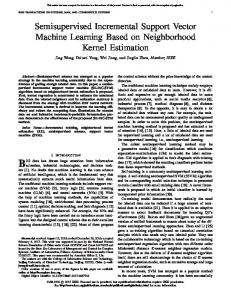
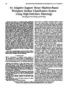
Fig. 1. (a) Waveform of a voltage disturbance and (b) its rms signature. Shadowed areas are the two transition segments.
optimization problems. The decision boundary with then modified by substituting
in (13) is
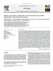
(16) Functions that satisfy Mercer’s theorem [16] are usable as kernel functions. Soft decision SVM is then applied. Examples of such kernels are given in Table I. The kernel parameters , , and are (like the regularization parameter ) input parameters to the SVM training process and shall be tuned to achieve sufficient classification performance. III. CHARACTERIZATION OF VOLTAGE DISTURBANCES A voltage disturbance is a sudden change in voltage waveform caused by short circuits, overloads or starting of heavy loads like motors etc. [17], [18]. In this section, we focus on identifying robust features that distinctively characterize voltage disturbances. Fail to find robust features may lead to a poor performance in the classification system. Fig. 1(a) shows the signal waveform of a typical voltage disturbance recording and its rms representation. Using the segmentation concept proposed in [6], we divide the disturbance rms signature (based on one-cycle window and updated each sample) into 5 segments I-V [Fig. 1(b)]: Segment I is the predisturbance segment which occurs before the triggering of the disturbance. Segment II is the first transition segment, which occurs just after the triggering has occurred. The voltage during segment III is stationary; it is followed by a
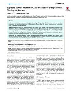
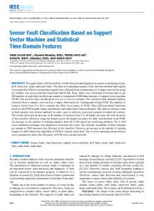
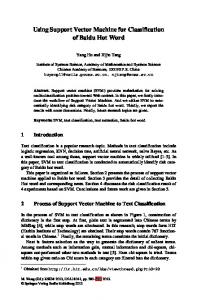
Fig. 2. RMS signatures of voltage disturbances due to a fault. (a) One faulty phase (D1) is shown. (b) Two faulty phases (D2) are shown. (c) Three faulty phases (D3) are shown. (d) Two faulty phases are shown where one of the phases is more affected than the other faulty phase (D4).
second transition segment (segment IV) at the end of the disturbance. Finally segment V starts after the voltage has returned to about its predisturbance level. In segment II and segment IV the voltage signal is nonstationary and hence no information can be obtained for feature extraction. Also segment I and segment V are of limited interest in terms of feature extraction since the disturbance has not yet started or it has passed. Hence the remaining segment used for feature extraction is segment III where the voltage disturbance is in its most stationary phase. This segment normally contains information that is unique enough to distinguish between different types of disturbances. Furthermore, features can be extracted both from the waveform and from the rms representation. Examples of features used for classification purposes are: the minimum rms voltage; the rms voltage at selected time instants; harmonic components (magnitude and phase) at selected time instants; total harmonic distortion; symmetric components and the duration of the disturbance [17]. This work concentrates on extracting features for classification of the most commonly appearing voltage disturbances. A. Voltage Disturbance Due to a Fault In a three-phase system there are mainly four different types of voltage disturbances due to a fault. Typical rms signatures for these types are shown in Fig. 2. The disturbances due to a fault have: 1) voltage magnitude drops in one phase [Fig. 2(a)]; 2) voltage magnitude drops in two phases [Fig. 2(b)]; 3) voltage
1300
IEEE TRANSACTIONS ON POWER DELIVERY, VOL. 22, NO. 3, JULY 2007
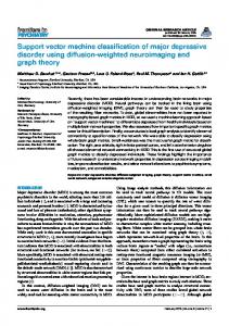
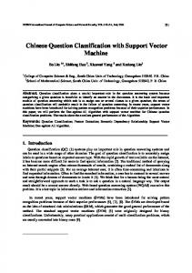
Fig. 4. Binary decision tree based on individual binary multiple class classification.
SVM
classifiers for
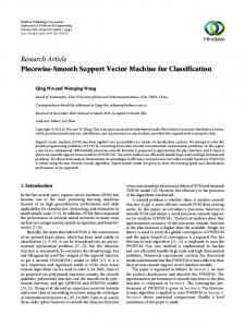
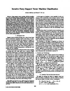
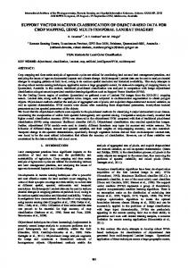
Fig. 3. (a) RMS signature of a voltage disturbance due to transformer energizing (disturbance type D5) is shown with (b) corresponding frequency domain representation. The FFT calculation was based on 512 waveform samples at a sampling rate of 12800 Hz.
magnitude drops in three phases; [Fig. 2(c)]; and 4) the voltage magnitude drops in two phases but one of these is more affected than the other one [Fig. 2(d)]. In the remainder of this paper these four disturbance types are referred to as disturbance type D1 to D4, respectively. Depending on the structure of the power network these disturbances originate from the following type of faults: single phase-to-ground fault, phase-to-phase fault, three-phase-fault and double phase-to ground. In general, all four types of disturbances due to a fault show changes in the rms signatures whilst the harmonics magnitudes and THD in segment III show low values. B. Voltage Disturbance Due to Transformer Energizing Another common type of voltage disturbance (referred to as disturbance type D5 in the remaining of this paper) is due to transformer saturation [6]. This type of disturbance is characterized by a sharp drop followed by gradual recovery of the voltage rms [Fig. 3(a)] to about its predisturbance level. Fig. 3(b) shows the magnitude spectrum of the disturbance. Relatively high magnitudes of even harmonics (especially 2nd and 4th harmonics) are produced as the transformer enters and exits the saturation. No load switching events were recorded in either study as this concerned medium-voltage networks for public distribution. C. Feature Extraction From above analysis the following features were extracted: 60 equally distanced rms values (i.e., 20 features per phase) were extracted with start at the triggering point of the disturbance. The remaining feature components were extracted from the frequency magnitude spectrum immediately after the first transition segment. The 2nd harmonics magnitude is chosen as a feature according to the discussion above. Also two odd harmonic magnitudes (5th and 9th) representing one lower and one higher frequency component are chosen as features. Finally, the total harmonics distortion (THD) with respect to the fundamental is the last feature selected. This gives a feature vector of 72 components per disturbance type (i.e., 24 features per phase).
Fig. 5. Block diagram of the training process.
IV. CLASSIFICATION SYSTEM The SVM classification system used in the experiments is shown in Fig. 4. To be able to classify disturbances D1-D5, ( )) and each five binary SVMs were used ( SVM was trained to classify one of the disturbances ,( ). Furthermore the SVMs were organized as mutual exwas trained to classify clusive classifier which means: , was trained to classify disturbance disturbance but class was removed from the training process since this . Hence for both class was already classified by and were removed from the training and so disturbances forth. A. Training Process The aim of the training process is to calculate the support vectors which are the parameters that define the optimal hyperplane. Fig. 5 shows the block-diagram of the training process. Input data are the sampled voltage waveforms from the three phases during the occurrence of the disturbance. Fig. 5 block (a) normalizes the rms input data to 1 p.u. with respect to the rms value in segment I (Fig. 1). This is done to reduce the risk of numerical problems. Block (b) is the feature extraction performed according to the description in Section III.
AXELBERG et al.: SUPPORT VECTOR MACHINE FOR CLASSIFICATION OF VOLTAGE DISTURBANCES
TABLE II NUMBER OF VOLTAGE DISTURBANCES AVAILABLE IN THE EXPERIMENTS
Block (c) is a second normalization according to the following formula:
where is the normalized feature value, and are the mean value and the standard deviation based on all the training is the number of features. samples of the -th feature and This normalization reduces the risk that feature components with large dynamic range dominate those having smaller ranges. -dimenFinally, the processed features are stored in a sional training matrix where each column represents one feature and each row represent one training sample. Block (d) is a 3-folded cross validation process for determining the values of parameter (regularization parameter) and parameter (RBF kernel parameter) that will give minimum classification error. and a prelabeled Input to block (d) is the training matrix -dimensional class vector (contains the class label to each training data). When parameters and are determined, the support vectors are calculated in block (e) according to (15) and hence the optimal hyperplane that separates the two classes is thereby also known. The SVM is ready to classify unseen data. V. EXPERIMENTAL TESTS AND RESULTS A. Data Used in the Experiments To test the performance of the proposed classification system, experiments were conducted using disturbances originated from real power networks and from synthetic data. Table II shows the number of disturbances available in the experiments. 1) Data Originating From the Power Networks: Disturbance data from power network A and power network B originate from two power networks in different countries in Europe. The disturbances were recorded by power quality analyzers and disturbance recorders and each disturbance recoding consists of 3 phases of voltage waveforms. The recordings includes a short prefault waveform (approximately 2 cycles long) followed by the actual disturbance. The nominal frequency of the power networks was 50 Hz and sampling frequencies of the instruments were 1000 Hz, 2000 Hz, or 4800 Hz. 2) Synthetic Data: The synthetic data was generated by using the power network simulation toolbox “SimPowerSystems” in Matlab. The model was a 11-kV network consisting of a generator, an incoming line feeding four outgoing lines via a busbar. The outgoing lines were connected to loads with different load characteristics in terms of active and reactive power. The disturbances were generated on one of these lines. In order to simu-
1301
TABLE III CONDUCTED EXPERIMENTS
TABLE IV CLASSIFICATION RESULT FOR EXPERIMENT I. TRAINING DATA AND TEST DATA ORIGINATE FROM POWER NETWORK A
late different waveforms the lengths of the incoming line and the outgoing lines as well as the duration of the disturbances were randomly generated within given limits. Finally the voltage disturbances were measured at the busbar. B. Conducted Experiments Six different types of experiments were conducted according to Table III. The philosophy behind the experiments is as follows: Experiment I was to ensure that the classifier system worked properly which was confirmed by making a classification when training data and test data originated from the same source (i.e., from power network A). Experiments II-V were the more important ones since in these experiments training data and testing data originating from different sources. Finally experiment VI was conducted to evaluate if the classification accuracy was increased (with respect to experiment V) if some amount of real data were added to the synthetic training data. C. Classification Results The results of the conducted experiments are given in Tables IV–IX. The tables contain the classification results in terms of number of correct classifications (diagonal elements) and misclassifications (the numbers outside the diagonal elements). Those test data that failed to be classified into any of the classes D1-D5 are found in column NC (not classified). Further the overall detection rate (i.e., the number of correct classified disturbances divided by the total number of disturbances) is also given in the tables. D. Comments to the Experiments The experiments are divided into two categories: 1) Experiments I-III involve data purely originating from recorded disturbances and 2) experiments IV-VI also involve synthetic data
1302
TABLE V CLASSIFICATION RESULT FOR EXPERIMENT II. TRAINING DATA ORIGINATE FROM POWER NETWORK A AND TEST DATA FROM POWER NETWORK B
TABLE VI CLASSIFICATION RESULT FOR EXPERIMENT III. TRAINING DATA ORIGINATE FROM POWER NETWORK B AND TEST DATA FROM POWER NETWORK A
TABLE VII CLASSIFICATION RESULT FOR EXPERIMENT IV. TRAINING DATA ORIGINATE FROM POWER NETWORK B AND TEST DATA FROM SYNTHETIC DATA
TABLE VIII CLASSIFICATION RESULT FOR EXPERIMENT V. TRAINING DATA ORIGINATE FROM SYNTHETIC DATA AND TEST DATA FROM POWER NETWORK B
TABLE IX CLASSIFICATION RESULT FOR EXPERIMENT VI. TRAINING DATA ORIGINATE FROM SYNTHETIC DATA (75%) AND FROM POWER NETWORK A (25%). TEST DATA ORIGINATE FROM POWER NETWORK B
. In experiment I both training data and testing data originate from the same power network. The data was therefore split into two equal parts and one part was used for training and the other
IEEE TRANSACTIONS ON POWER DELIVERY, VOL. 22, NO. 3, JULY 2007
was used as test data to validate the classifier. The individual detection rates and the overall detection rate for experiment I were sufficiently high validating that the SVM classifier works properly. Experiment I was also the only one where the performance in classifying disturbance D5 (transformer energizing) could be evaluated since power network B and the synthetic data did not include type D5 disturbances. In experiment II and experiment III training data and test data originate from different power networks. Despite that, high overall detection rates were achieved. Especially encouraging was that high detection rates were preserved also when training data and test data were shifted, indicating that the selected features are robust. The remaining experiments included synthetic data. Experiment IV shows excellent detection rate (95.9%) when the classifier was trained on real data and test data was purely synthetic. Hence, the classifier shows high generalization capability since the synthetic data show somewhat different characteristics compared to the data originating from the power network. The remaining two experiments were performed in order to evaluate the classification accuracy when the classifier was trained on synthetic data. It is important to notice that the variance between the feature components for synthetic data is less than the variance for a real power network. As a consequence, the generalization capability is therefore believed to be less compared to a classifier trained on real data. Experiment V also confirmed that. Lower individual detection rates as well as lower overall detection rate was achieved. It should also be noticed that the classifier fails to classify type D4 in experiment V. As seen in Table VIII, the classifier classifies disturbance type D4 mainly to type D1 or type D2 (and some to NC as well). The reason is because the synthetic training data of type D4 is not enough distinguished from the synthetic training data of type D1 and D2. There are at least two ways to solve such a situation. One is to refine the simulation model and the other is to add some amount of training data from a real power network to the synthetic training data. The latter was conducted in experiment VI where 25% data from power network A were added to the synthetic training data. As a result, the number of misclassifications decreased significantly for disturbance types D1-D3 due to the increased variance in the training data. This approach did not significantly increase the detection rate for disturbance type D4. However by refining the simulation model also type D4 disturbance will be classified with the same high accuracy as for the other disturbances. VI. CONCLUSION This paper proposes a novel method based on the SVM algorithm for classification of common types of voltage disturbances. The results from the conducted experiments have shown high classification accuracy, implying that the SVM classification technique is an attractive choice for classification of this type of data. The accuracy of the proposed method is also dependent on the selected features used for the classifier. The work described in this paper has shown that by using features extracted both from time-domain and frequency-domain, the SVM classifier yields high performance. The proposed classifier is shown to be effective by using individually trained SVMs as nodes in a binary decision tree for multiple class classification. The advantage is
AXELBERG et al.: SUPPORT VECTOR MACHINE FOR CLASSIFICATION OF VOLTAGE DISTURBANCES
that it is straight forward to extend the system when new types of disturbances are added to the classifier. In this work, data were used from two different power networks as well as synthetic data in order to evaluate the performance of the SVM classifier. High performance was achieved when the training data were originated from the power network and slightly less accuracy was achieved when the classifier was trained on synthetic data. However, by adding training data originated from a real power network to the synthetic training data set, the classification performance increased significantly. From an implementation standpoint, it is highly demanded that the classifier is based purely on synthetic data since synthetic data are easier to obtain as compared to real data. ACKNOWLEDGMENT The authors would like to thank J. Carlsson of Unipower AB, A. Ferguson of Scottish Power Power Systems, and A. Berlin and T. Gustafsson of Vattenfall Eldistribution AB for their contributions.
1303
[13] L. S. Moulin, A. P. A. da Silva, M. A. El-Sharkawi, and R. J. Marks, II, “Support vector machines for transient stability analysis of large-scale power systems,” IEEE Trans. Power Syst., vol. 19, no. 2, pp. 818–825, May 2004. [14] H. He and J. A. Starzyk, “A self-organizing learning array system for power quality classification based on wavelet transform,” IEEE Trans. Power Del., vol. 21, no. 1, pp. 286–295, Jan. 2006. [15] D. Thukaram, H. P. Khincha, and H. P. Vijaynarasimha, “Artificial neural network and support vector machine approach for locating faults in radial distribution systems,” IEEE Trans. Power Del., vol. 20, no. 2, pt. 1, pp. 710–720, Apr. 2005. [16] J. Lundgren, M. Rönnqvist, and P. Värbrand, Linjär och Ickelinjär Optimering. Lund, Sweden: Studentlitteratur, 2001. [17] M. H. J. Bollen and I. Y. H. Gu, Signal Processing of Power Quality Disturbances. : IEEE Press, to be published. [18] M. H. J. Bollen and E. Styvaktatis, “Characterization of three-phase unbalanced dips (as easy as one two three?),” in Proc. IEEE Power Eng. Soc. Summer Meeting, Seattle, WA, Jul. 16–20, 2000, vol. 2, pp. 899–904. Peter G. V. Axelberg received the M.Sc and Tech. Lic. degrees from Chalmers University of Technology, Gothenburg, Sweden, in 1984 and 2003, respectively. From 1984 to 1992, he was with ABB Kabeldon, Alingsås, Sweden. Since 1992, he has been a Senior Lecturer with the University College of Borås, Borås, Sweden. In 1992, he co-founded Unipower, where he has been active as manager of business relations and research. His research activities are focused on power quality measurement techniques.
REFERENCES [1] M. H. J. Bollen, Understanding Power Quality Problems, Voltage Sags and Interruptions. Piscataway, NJ: IEEE Press, 2000. [2] M. H. J. Bollen, “Algorithms for characterizing measured three-phase unbalanced voltage dips,” IEEE Trans. Power Del., vol. 18, no. 3, pp. 937–944, Jul. 2003. [3] A. M. Gouda, M. M. A. Salama, M. R. Sultan, and A. Y. Chikani, “Application of multiresolution signal decomposition for monitoring short-duration variations in distribution systems,” IEEE Trans. Power Del., vol. 15, no. 2, pp. 478–485, Apr. 2000. [4] M. Karimi, H. Mokhtari, and M. R. Irvani, “Wavelet based on-line disturbance detection for power quality application,” IEEE Trans. Power Del., vol. 15, no. 4, pp. 1212–1220, Oct. 2000. [5] I. Gu, N. Ernberg, M. Styvtakis, and M. Bollen, “A statistical-based sequential method for fast online detection of fault-induced voltage dips,” IEEE Trans. Power Del., vol. 19, no. 2, pp. 497–504, Apr. 2004. [6] M. Styvaktakis, “Automating Power Quality,” Doctor of Philosophy, Chalmers Univ. Technol., Gothenburg, Sweden, 2002. [7] J. Huang, M. Negnevitsky, and D. T. Nguyen, “A neural-fuzzy classifier for recognition of power quality disturbances,” IEEE Trans. Power Del., vol. 15, no. 2, pp. 609–616, Apr. 2000. [8] S. Santoso, J. Lamoree, W. M. Grady, E. J. Powers, and S. C. Bhatt, “A scalable PQ event classification system,” IEEE Trans. Power Del., vol. 15, no. 2, pp. 738–743, Apr. 2002. [9] S. Santoso, E. J. powers, W. M. Grady, and A. C. Parsons, “Power quality disturbance waveform recognition using wavelet based neural classifier part I: Theoretical foundation,” IEEE Trans. Power Del., vol. 15, no. 1, pp. 222–228, Jan. 2000. [10] J. V. Wijayakulasooriya, G. A. Putrus, and P. D. Minns, “Electric powerquality disturbance classification using self-adapting artificial neural networks,” Proc. Inst. Elect. Eng., Gen. Transm. Distrib., vol. 149, no. 1, pp. 98–101, Jan. 2002. [11] V. N. Vapnik, Statistical Learning Theory. New York: Wiley, 1998. [12] N. Cristianini and J. Shawe-Taylor, An Introduction to Support Vector Machines. Cambridge, MA: Cambridge Univ. Press, 2000.
Irene Yu-Hua Gu (M’94–SM’03) received the Ph.D. degree in electrical engineering from the Eindhoven University of Technology, Eindhoven, The Netherlands, in 1992. She was a Research Fellow with Philips Research Institute IPO, The Netherlands, and Staffordshire University, Staffordshire, U.K., and a Lecturer with The University of Birmingham, Birmingham, U.K., from 1992 to 1996. Since 1996, she has been with the Department of Signals and Systems, Chalmers University of Technology, Gothenburg, Sweden, where she is currently a Professor. Her research interests include signal processing applications to electric power system disturbance analysis and classification, signal and image processing, video surveillance, and video communications. Dr. Gu was an Associate Editor for the IEEE TRANSACTIONS ON SYSTEMS, MAN, AND CYBERNETICS–PART A: SYSTEMS AND HUMANS and PART B: CYBERNETICS, from 2000 to 2005, and has been with the Editorial Board of EURASIP Journal on Advances in Signal Processing since 2005, and Chair of IEEE Swedish Signal Processing Chapter during 2002–2004.
Math H. J. Bollen (M’93–SM’96–F’05) received the M.Sc. and Ph.D. degrees from Eindhoven University of Technology, Eindhoven, The Netherlands, in 1985 and 1989, respectively. Currently, he is Manager of Power Quality and Electromagnetic Compatibility (EMC) with STRI AB, Ludvika, Sweden, and Guest Professor at EMC-on-Site, Luleå University of Technology, Skellefteå, Sweden. Before joining STRI in 2003, he was Research Associate at the Eindhoven University of Technology; Lecturer at the University of Manchester Institute of Science and Technology (UMIST), Manchester, U.K.; and Professor of Electric Power Systems at Chalmers University of Technology, Gothenburg, Sweden. His research interests cover various aspects of power quality and reliability. He has published a number of fundamental papers on voltage dip analysis and a textbook on power quality. Dr. Bollen is active in IEEE, CIGRE, and IEC working groups on power quality.