TOOL WEAR MONITORING USING WAVELET BASED MULTIFRACTAL ANALYSIS A. OUAHABI, W. RMILI, D. AIT AOUIT, S. JAFFARD+, R. SERRA Ecole Polytechnique de l’Université de Tours-Polytech’Tours 7, avenue Marcel Dassault, 37200 Tours, France Tel. (00) 33 2 47 36 13 23- Fax. (00) 33 2 47 36 13 11- E-mail :
[email protected] + Centre de Mathématiques, Faculté des Sciences et Technologie, Université Paris XII, Créteil, France E-mail :
[email protected]
ABSTRACT - Several signal processing techniques based on time-frequency analysis and
wavelet are proposed in order to extract a large number of indicators of the cutting tool state. The scaling of the vibration process is characterized by sample paths that present a high variability. This irregular behaviour can fruitfully be analyzed in terms of Hölder exponent. For a wide variety of processes, usually referred to as multifractal processes, the Hölder exponent is not constant along the sample paths but instead varies widely, apparently erratically, from one time position to another. The variability of this Hölder exponent can be described through the multifractal (or singularity) spectrum. In this study, multifractal functions are used as models for vibratory signals whose regularity may change abruptly from one point to the next. The method is based on the changes in the vibration signatures acquired during the turning operation over the tool life. The main objective of this paper is to develop a new signal processing technique using vibratory signals in order to provide an efficient tool wear monitoring system able to increase machining performance.
KEYWORDS - Cutting tool, Hölder exponent, machining, multifractals, time-frequency, vibration, wavelet
1. INTRODUCTION Multifractal analysis is a recent field, introduced in the context of turbulence in the mid 80s; its purpose is to analyze the pointwise Hölder regularity of signals and to understand how the regularity fluctuates from point to point. Multifractal formalism has proven particularly fruitful in the characterization of singular measures arising in a variety of physical situations [2]. This formalism accounts for the statiscal scaling properties of these measures through the determination of their singularity spectrum f , which is intimately related to the generalized fractal dimensions Dq . The
f singularity spectrum provides a rather intuitive description of a multifractal measure in terms of interwoven sets of Hausdorf dimension f corresponding to singularity strength . We will give a detailed account of the interaction between wavelet analysis and multifractal analysis. This interaction was made possible because of two remarkable properties of wavelet expansions:
1
- It is possible to characterize the pointwise Hölder regularity of a signal by simple estimates on the decay rate of its wavelet coefficients, corresponding to the wavelets localized near the point considered. - Wavelets are unconditional bases of “most” function spaces. The second point is relevant because a central problem in multifractal analysis is to relate the spectrum of singularities of a signal X to the function spaces which contain X. Formulas which perform this bridge are called multifractal formalisms. Therefore, performing the multifractal analysis of a function (or of a signal) X means to determine (or to estimate) its spectrum of singularities. In this study, multifractal functions are used as models for vibratory signals whose regularity may change abruptly from one point to the next. The method is based on the changes in the vibration signatures acquired during the turning operation over the tool life. This paper is split into four parts: Section 2 is introductory; we define the pointwise Hölder regularity, the notion of dimension that we will use and the wavelet characterization of the pointwise Hölder exponent using the WTMM (wavelet transform modulus maxima) approach. Section 3 is devoted to the experimental set-up and data acquisition. Results of the application of these techniques to vibratory signals are discussed in Section 4.
2. WAVELET BASED MULTIFRACTAL ANALYSIS 2.1 Pointwise Regularity and Hölder Exponent Multifractal functions are used as models for signals whose regularity may change abruptly from one point to the next. Our first task is therefore to define what is meant by pointwise regularity. It is a way to quantify, using a positive parameter , the fact that the graph of a signal may be more or less “ruguous” at a point t 0 . Let X (t )tR denote the sample path of the function or stochastic process of interest. Its local regularity is commonly studied via the notion of pointwise Hölder exponent [1] and [5]. Definition 1. Let t0 and let 0 . A locally bounded signal X : R R belongs to C (t 0 ) if there exists a constant and a polynomial P satisfying deg(P) and such that, in a neighborhood of t 0 , The Hölder exponent of X at t0 is
X (t ) P (t t 0 ) C t t 0
h (t 0 ) sup : X C (t 0 )
If h(t 0 ) 1 , then the polynomial P(t t 0 ) simplifies to X (t 0 ) . A famous though simple example is given by the function X (t ) A B t t 0 h , whose Hölder exponent (sometimes also called the singularity strength) at t0 is simply h.
2.2. Multifractal Spectrum Processes with scaling are usually characterized by sample paths that present a high variability [4]. This irregular behaviour can fruitfully be analyzed in terms of Hölder 2
exponent. For a wide variety of processes, usually referred to as multifractal processes, the Hölder exponent is not constant along the sample paths but instead varies widely, apparently erratically, from one time position to another. The variability of this Hölder exponent can be described through the multifractal (or singularity) spectrum, D(h), which consists of the Hausdorff dimension of the set of points with Hölder exponent h. Through the Legendre transform of D(h), one can define another function of q: (q) inf 1 qh D(h) h
Definition 2. We denote by E h the set of points where the Hölder exponent takes the value h. The spectrum of singularities D(h) of X consists of the Hausdorff dimension of E h . (By convention, dim(Ø)= .) ) By definition of the Hausdorff dimension [4] and [5], the multifractal spectrum takes values in 0,1 . Furthermore, we will assume without loss of generality that D(h) differs from in a finite range of Hölder exponents:
D(h) , h h* , h*
In applications, D(h) has often been used as a tool to analyze/classify empirical time series (to detect pathologies in medicine, to model information fluxed in Internet traffic). Roughly speaking, it pictures the roughness or irregularity along time of the analyzed time series. For instance, the range h* , h* of existing singularity strengths is often used to classify data.
2.3. Wavelet Coefficients Let 0 (t ) denote a reference pattern called the mother-wavelet. It is usually requested that 0 possesses jointly strongly concentrated time and frequency supports: It therefore acts as an elementary atom of information. The reconstruction property implies that satisfy 0 the socalled admissibility condition:
0 (t ) dt
0
R
The mother wavelet is also characterized by a strictly positive integer N 1 , called its number of vanishing moments, defined as: k 0,1, , N 1,
t k
0 (t ) dt
0,
R
Let j ,k (t ) 2 0 2 t k j N, k N j
j
t N 0 (t ) dt 0.
R
denote templates of 0 dilated to scales 2 j and
translated to time positions 2 j k . Let X (t ), t R denote the continuous time series (or function) to be analyzed. The discrete wavelet transform of X is defined through the computation of its coefficients d X j, k as: d X j, k
X (t )2
j
0 2 j t k dt
R
2.4. Wavelet Transform Modulus Maxima Wavelet transform modulus maxima method (WTMM) is initially introduced by S. Mallat [6] and developed, in the context of the thermodynamics of fractals, by Arneodo and co-authors [2]. To date, it remains one of the most widely used tools for empirical multifractal analysis performed in actual applications.
3
Assume that is a wavelet, i.e. a well localized function with enough vanishing moments (in practice a derivative or a second derivative of a Gaussian is often used). One computes the continuous wavelet transform of X W X ( a, t )
1 a
u t du a
X (u)
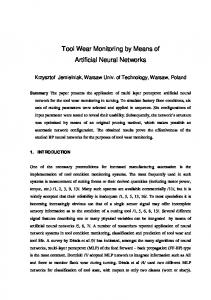
defined in the upper half plane (a, t ) : a 0, t R. For each scale a, one spots the local maxima of the functions t W X (a, t ) . These local maxima are connected through scales, thus yielding the wavelet skeleton. At each local maximum located at position (a, t) in the time scale plane, one associates the supremum of the wavelet transform on the sub-skeleton issued from (a, t) (i.e. the maximum on the part of the skeleton which is linked to (a, t) and corresponds to values of the scale parameter smaller than a). Historically, the WTMM has been the first and remained for a long time the only multifractal formalism yielding correct results. However, a number of important differences between the wavelet leaders and WTMM approaches can be pointed out [1], [3] and [7] . On the computational side, an important drawback of the WTMM lies in its computational cost. It is based on the computation of a full continuous wavelet transform followed by the skeletization and maxima tracking procedures (see figure 1). a)
b)
Figure 1. (a) Example of signal with singularities, (b) Its WTMM and skeletization.
3. EXPERIMENTAL SET-UP AND DATA ACQUISITION 3.1 Machining procedure Cutting experiments are conducted using a computer numerically controlled lathe (CNC) type SOMAB « Unimab 450 » as shown in figure 2. The workpiece material is a gray iron (FGL 250) and the cutting tool insert is a CNMG 1204 085B OR2500. Cutting operations are realized without applying cutting fluid and all cutting experiment are performed under the following cutting conditions: cutting speed = 340 m/mn, feed = 0.18
4
mm/rev and depth of cut = 1.5 mm. To validate statistically our experimental approach, thirty cutting tool insert are used.
X
Z Y 1.1 Vibratory acquisition Figure 2 – CNC Lathe and acquisition system.
Figure 3 – Sensors on the tool holder.
In this study, a monitoring strategy is realized using triaxis piezo-electric accelerometer Brüel&Kjaer 4507. This accelerometer is fixed on the tool holder to allow measurement according the three directions X, Y and Z (see figure 3). This generate a large number of features, which was helpful to acquire maximum information about the tool wear state. The sensor signals are acquired for 70s duration of observation, sampled at 16.38 kHz with 0.25 Hz frequency resolution. Each signal contained 1000000 samples. Collected data was stored directly on the PC hard drive (figure 2) by means of the Pulse Lab Shop® software developed by Brüel&Kjaer. Signal processing was performed with Matlab software (Mathworks, version 6.5).
3.2 Direct control of cutting tool In order to validate the vibratory acquisitions, we also used a specific optical technique based on white light interferometry. This technique was the vertical scanning interferometry (VSI) performed on a Wyko® NT-2000 optical profiler. To evaluate the degree of tool wear after each cutting experiment, flank wear is measured by scanning major flank. Figure 4 shows 3D measurements of new insert and typical flank wear generated in this insert. Widths of all the tool wear are calculated during cutting tool life. 0.1 mm
a)
b)
0.1 mm
0.30 mm
Figure 4 – 3 D images issued from optical profiler: a) New insert, b) Worn insert (last experiment).
5
4.
RESULTS AND DISCUSSION
4.1. Flank wear evolution Flank wear is followed by plotting flank widths versus cutting experiments. The result is shown in figure 5. In this figure, three domains could be distinguished: (1) breaking-in period of the insert, (2) tool wear stabilization where the flank wear progressed uniformly and (3) tool wear acceleration where the wear rate increases until rapid breakdown of the tool occurs.
3
1
2
Experiment [mn] Figure 5 - Evolution of flank wear versus cutting experiment.
4.2 Vibratory analysis We show in figure 6 and figure 7 an example for 11 experiments of temporal signal (11 minutes) and time(experiment)-frequency representation respectively according to the X direction. These experiments correspond to lifespan of cutting tool. 300 200
Last experiment First
experiment 100 ]² s / 0 [m n o ti a -100 r lé é c c A -200 -300 -400
0
2
4
6
8
10
12
14 6
x 10
Figure 6 – Vibratory responses acquired during tool life
6
8
x 10 14
Acceleration [m/s²]²
12 10 8 6 4 8000
2
6000
0 0
4000 2
4
6
2000
8
Experiment [mn]
10
12
Frequency [Hz]
0
Figure 7 – Time-frequency representation obtained from the new insert up to final of lifespan of insert
In order to analyze the vibratory signals in the time-frequency domain, it is more judicious to study their spectrograms.
4
a)
6000
4
x 10 5
4
5000
b)
6000
4.5
4.5 4
5000
3.5
] 4000 z H [ y c n 3000 e u q re F 2000
3 2.5 2 1.5
] z 4000 H [ y c n 3000 e u q e r F 2000
0.5 0
0
10
20
30
40
50
60
x 10 5
c)
6000
4.5 4
5000
3.5 3 2.5 2 1.5
1
1000
4
x 10 5
0
Time [s]
1
1000
3.5
] z 4000 H [ y c n 3000 e u q e r F 2000
3 2.5 2 1.5 1
1000
0.5 0
0
10
20
30
Time [s]
40
50
0
0.5 0
0
10
20
30
40
50
Time [s]
Figure 8 - Spectrograms obtained in the case of: a)First experiment, b) 6th experiment and c)Last experiment
We plot, in figure 8, spectrograms for one cutting tool insert from its first use to its lifespan limit. These spectrograms exhibit two frequency bands centered in the vicinity of 4200 Hz and 5100 Hz corresponding to the eigen (natural) frequencies of the couple cutting tool-tool holder. From the third experiment, we also note the appearance of a spectral band centered near 2800 Hz. This can be interpreted like a mode created by the contact of the matter and the tool. Examination of these spectrograms indicates that the vibratory level of these characteristic frequencies increases gradually with the deterioration of the cutting plate used.
4.3. Multifractal analysis Multifractal analysis is a technique which can be used for the characterisation of complexity and irregularity. Based on the concept of fractal dimensions, these descriptors examine also the scaling properties of a measure by considering singularities that may be subsequently characterised by two indices: the strength of the singularities, and f the singularity strength
7
0
distribution. The multifractal spectrum [8] is described by a series of dimensions, f each possessing a singularity strength . The f spectrum is characteristic in shape and displays features which are intrinsic to the set under investigation. For a situation of perfect similarity, the f curve collapses to a single point at f . Sets exhibiting non uniformity display markedly different behaviour, heterogeneity indicated by a broad f spectrum. Figure 8 demonstrates the potential of using multifractal analysis of vibratory signals. Indeed, multifractal f spectra calculated from the experiments 1, 6, 8 and 11 from vibratory responses acquired during tool life (see figure 4) are significantly different. The experiment showing breakdown of the tool (experiment 11) is characterised by a symmetrical f spectrum with data points distributed equally around the point f 1 . For the case of poorer dispersion quality (experiment 1, 6, and 8), strong asymmetry is observed. On the basis that for the situation of perfect similarity the f curve collapses to a single point, it could be argued that the width of the f curve is representative of the state of tool wear. Namely, the narrower the f curve width, the better the state of tool wear. If curve width is described in terms of max min for the range of q exponents investigated, then the results from experiments 1 and 11 are 0.3089 and 0.4373 respectively (as shown in Table 1). In relation to the evolution of flank wear versus cutting experiment in figure 5, the use of curve width measurements appears to be justified. Examination of experiments 1, 6, 8 and 11 illustrated in Table 1 and figure 9 similarly indicates that tool wear acceleration may be associated with higher values of the measure max min and the presence of spectral symmetry. Table 1 Width of the f spectrum from experiment 1 to experiment 11. Experiments number Experiment 1 Experiment 6 Experiment 8 Experiment 11
αmax 1.1847 1.2384 1.2296 1.2427
αmin 0.8758 0.9194 0.8312 0.8054
∆α 0.3089 0.3190 0.3984 0.4373
5. CONCLUSIONS This study investigates the use of vibration measurements to perform the tool-failure detection using different methods of analysis. It is shown that during the turning process, the state of the cutting tool as observed using an optical profiler is closely related with some parameters obtained from vibratory signal processing: spectal analysis, time-frequency analysis and multifractal analysis. The originality of this paper is the use of multifactal analysis based on MMWT (Wavelet transform modulus maxima) applied to vibratory signals. In this study, we have shown that the vibratory response acquired during machining process has a multifractal behavior. This nature enabled us to characterize tool wear using multifractal analysis. This new approach that seems promising opens new opportunities for the community of signal and image processing, materials and machining monitoring.
8
experiment 1 experiment 6 experiment 8 experiment 11
Figure 9 - f spectra from experiment 1 to experiment 11.
References:
1 Abry, P., S. Jaffard, B. Lashermes. Revisiting scaling, multifractal, and multiplicative cascades with the wavelet leaders lens. SPIE proceedings series, Vol. 5607, pp. 103-117, Novembre 2004. 2. Arneodo, A., E. Bacry, J. Muzy. The thermodynamics of fractals revisited with wavelets. Physica A 213, pp. 232–275, 1995. 3. Jaffard, S. Wavelet techniques in multifractal analysis. In Fractal Geometry and Applications: A Jubilee of Benoit Mandelbrot. eds. M. Lapidus et M. van Frankenhuysen, Proc. of Symp. in Pure Mathematics, 2004. 4. Jaffard, S. Multifractal formalism for functions, part I: Results valid for all functions. S.I.A.M. J. Math. Anal. 28(4), pp. 944–970, 1997. 5. Jaffard, S. Exposants de Hölder en des points données et coefficients d’ondelettes. C. R. Acad. Sci. Sér. I Math. 308, pp. 79–81, 1989. 6. Mallat, S., A Wavelet Tour of Signal Processing, Academic Press, San Diego, CA, 1998. 7. Ouahabi, A., D. Ait Aouit. Ondelettes et fractales pour l’analyse du signal et de l’image. In optimisation en traitement du Signal et de l’Image , (IC2), Hermès-Lavoisier, 2007. 8. A. Ouahabi, D. Ait Aouit. Ondelettes et multifracales. Ecole Analyse Multirésolution pour l’Image. Lyon 20-22 mars 2007.
9