Towards a UML Profile for HLA Federation Design, Part II* Okan Topcu
Halit Oguztuzun
Mark Gerald Hazen
Virtual Combat Systems Group Defence R&D Canada-Atlantic Dartmouth, N.S. Canada
[email protected]
Department of Computer Eng. Middle East Technical University 06531 Ankara, Turkey
[email protected]
Virtual Combat Systems Group Defence R&D Canada-Atlantic Dartmouth, N.S. Canada
[email protected]
Keywords: High Level Architecture, FEDEP, UML Profile Abstract This paper*proposes a set of metamodel extensions to UML for HLA federation design to support a more formalized and standardized description of the federation and federate design and documentation. In most cases a combination of this proposed profile and predefined standard UML model elements will be an effective way to design and document an HLA based simulation. INTRODUCTION The Federation Development and Execution Process (FEDEP) Model identifies and describes the activities necessary to develop a High Level Architecture (HLA) federation [1]. Although it has defined some activities to design federations, the design notations and documentation standards of HLA-based simulations are left to designers. Clear and complete design documentation is essential for communication within project teams and to assure architectural soundness. Understanding and communicating the architecture of a federation by using Federation Object Models (FOM) and Simulation Object Models (SOM) can be difficult and the FEDEP process does not provide adequate support for the design and documentation of federations. Also, as it is stated in [2], a FOM/SOM only captures a limited, one-dimensional view of the federation data, parameters, and interactions, excluding many other types of data relevant to the operation of a federation (e.g., dynamic interests of federates). In the references [2, 3], the need for enhancing the federation design graphically and semantically is discussed and the Unified Modeling Language (UML) [4] is proposed as a solution. UML is generic and extensible so that it can be tailored to the needs of a particular application domain and it allows the modeler to add new modeling elements to create UML models for process-specific or implementation-language-specific domains (for example, supporting code generation for a particular infrastructure).
*
This work has been partially supported by DRDC Atlantic under the terms of NATO Fellowship Program
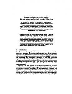
Development of HLA-specific extensions to UML, which will support a more formalized and standardized description of the federation, federate design, and documentation issues, will produce the following gains: • A more formalized federation design; • Alternative ways of viewing the federation, such as: structural view, behavioral view, implementation view, and deployment view; • The ability to capture dynamic data interests, which the HLA Object Model Template (OMT) does not attempt; • Access to many UML-based software CASE tools, which provide automation for modeling, syntax checking, verification, and code generation, for HLA based simulation development; • Improvement in the communication between conceptual modelers, software engineers, programmers, simulation engineers and users through the use of a common modeling language; and • Improved support for Verification and Validation (V&V) activities due to increased precision in the description of the federation design. The envisioned UML extension for HLA should address the key activities in the federation design and development stages of FEDEP. The framework of our vision is depicted in the Figure 1. The initial work for a UML extension for HLA is presented in [3]. The present paper is a continuation of this work, and it features two sections: HLA management package specification; and a simple case study to demonstrate how the proposed diagrams can be used in federation design. First, the proposed UML profile is overviewed, and then the management package is explained in greater detail. UML PROFILE OVERVIEW A UML profile is defined as a stereotyped package that contains model elements that have been customized for a specific domain or purpose by extending the metamodel using stereotypes, tagged definitions, and constraints. It provides mechanisms for applying and specializing the standard UML Metamodel for a particular environment or domain [4].
FEDERATION CONCEPTUAL MODEL FCM
FCM y Requirements y Application Domain Concepts y Ontologies
FEDERATION DESIGN MODEL FDM Declaration Management Data Distribution Management Time Management Object Management Federation Management Ownership Management Execution Environment
Federates A,B,C Objects 1,2,3
FDM encapsulates these interfaces by utilizing UML diagrams such as: o Class-Based P/S Diagrams o Federate-Based P/S Diagrams
DEVELOPMENT
AUTOMATED: o Federate HLA Specific Code o FED File o RID File o FEPW o FOM o SOM
Diagram Illustration AFd
BFd
Publish
Obj-1
Subscribe
Figure 1. Environment for HLA Federation Development
This section introduces a UML Profile for HLA federation design, defined in terms of the UML’s extensibility mechanisms, particularly stereotypes and constraints, to lay the semantic groundwork for a visual notation for HLA federation design. Federation design is based on a representation of the real world domain of interest in terms of the HLA object model. A visual notation and associated tools for federation design as a whole, and for OMT components, in particular, should facilitate tractability and understandability for complex or large-scale federation designs. To this end, a UML profile for HLA
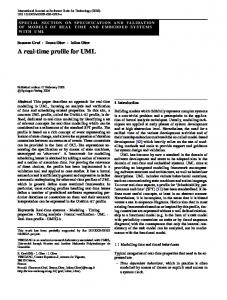
federation design is developed, specifically addressing HLA Object Model Template and HLA Interface Specification (RTI services) [5, 6, 7]. The complexity of the UML profile is managed by organizing it into logical packages and models. Within each package, the model elements are defined in the following terms: its abstract syntax, its well-formedness rules, and its semantics. The UML profile for HLA federation design comprises several related models as depicted in the Figure 2 and the models and packages are described in Table 1.
Table 1. CM Development/Representation/Validation STEREOTYPE
BASE CLASS
DESCRIPTION
Federation Design Model (FDM) Object Model
Model
Federation Design Model (FDM) is an instance of a UML metamodel. The primary responsibility of the model layer is to define a language to describe an HLA-compliant federation design.
Model
FOM
Model
Object Model represents the HLA Object Model Template (OMT). This package specifies the core constructs required for HLA federations. It contains sufficient semantics for the FDM, which in turn serves as the infrastructure for the rest of the FDM. It includes FOM, SOM and OMTCore packages. Federation Object Model (FOM) is a model to describe all shared information between federates essential to a particular federation.
SOM
Model
Simulation Object Model (SOM) describes the particular data interests of a federate.
OMTCore
Package
OMTCore package contains the base elements defined in the HLA Object Model Template specification, namely, HLAClass, ObjectClass, InteractionClass, federate, Mask, ObjectAttribute, InteractionParameter, PSKind, ISRKind, URKind, TAKind, UpdateKind stereotypes.
HLAservices
Package
HLAservices package is for HLA federation design pertaining to HLA Interface specification and related management services of runtime infrastructure (RTI), namely, Federation Management (FM), Data Declaration Management (DM), Object Management (OM), Time Management (TM), Ownership Management (OwM), and Data Distribution Management (DDM).
This paper will discuss the “HLA Services” package while the “Object Model” package and its sub-packages are defined and explained in [3].
2. Subscribe Association Class Subscribe is a one-way relation from HLAClass to federate and it is used for declaring the federate interests in the HLAClass.
Federation Design Model
Object Model
HLAServices
SOM
FOM
Figure 4. Subscribe Stereotype Notation OMTCore
OMTCore
Figure 2. Top Level Packages
HLA SERVICES (HLAServices) PACKAGE HLAservices package contains specialized UML stereotypes to support HLA federation design. A combination of this package and predefined UML model elements and views is expected to be an effective way to design an HLA federation. HLAServices package introduces some new stereotypes as well as some diagrams to emphasize the structure and functionality of the federation.
attribute_list: The list of attributes that a subscriber federate requires to be notified about when an instance of this class or one of its subclasses is generated or updated during federation execution. 3. RoutingSpace Stereotype Label is the name of the routing space and it is compulsory. The attribute information icon reveals the range, units, and normalization function information as depicted in the Figure 5. Label Dimension : Type
STREOTYPES IN THE PACKAGE A stereotype is a model element that defines additional values (based on tag definitions), additional constraints, and, optionally, a new graphical representation. The notation for each element is shown by an attached figure. Note that most elements in this package are based on the Object Model package, which was introduced in [3]. 1. Publish Association Class A publish association between an HLAClass and federate stereotypes indicates that the federate is capable of generating instances of the HLAClass. The publish association is a one-way relation, which encapsulates registerObject() or sendInteraction() interface calls according to the HLAClass. When a federate publishes an HLA class, then it also creates (registers) the object.
X
Range (min,max), Units, Normalization Function
Figure 5. RoutingSpace Stereotype Notation
4. Region Stereotype Regions are instances of routing spaces, so before creating a region, a RoutingSpace stereotype should be defined. A region name, UpperBound and LowerBound attributes are compulsory. RegionName:Space Dimension (LowerBound,UpperBound)
OR
RegionName
Figure 6. Region Stereotype Notation
Figure 3. Publish Stereotype Notation
attribute_list: The list of attributes, which will be generated and updated during federation execution.
5. Association with Publish and Subscribe Stereotypes When a region stereotype is associated with a publish or subscribe stereotype, it means that the publication or subscription to a specified HLAClass will take place in the specified region. For example, when such an association is made in the federation design, instead of interface call subscribeInteractionClass(), the interface call subscribeInteractionClassWithRegion() should be used. The parameters for this call will be supplied by both publish and region stereotypes. Figure 7 shows an example of how to use these stereotypes.
X
AFd
P(b,e,f,g)
Region:Alpha
a b c d e f g
S(a,b,c,d,e)
BFd
Region:Gam ma
Figure 7. HLA Data Distribution Integrated Diagram
DIAGRAM VIEWS Although, for many HLA-specific tasks (such as federation creation, taking ownership of an object, etc.), the standard UML diagrams (e.g., Activity diagrams, class diagrams, state diagrams, etc.) can be used, the use of the following diagrams is encouraged especially when the federate-HLA object relations are to be emphasized. The example diagrams are presented in the case study in part 2. 1. General Publish/Subscribe (P/S) Diagrams In federation design, it is essential to express the relationship between a federate and particular federation objects. The Publish/Subscribe pattern forms the basis of the model of communication used by HLA between federates in terms of objects and interactions. At runtime, software components can specify to the HLA runtime infrastructure (RTI), which plays the role of an object request broker, a set of data types they can provide, and a set of data types they are ready to receive according to Federation Object Model (FOM) and Federation Execution Data (FED). Publishing means providing data, which is composed of object classes and attributes, and interaction classes that the federate is able to update or send. Subscribing means expressing interest in receiving data. The general P/S diagram is a graph of Publish and Subscribe association stereotype elements connected by their various static relationships. It depicts all of the capabilities of member federates in terms of the objects and interactions that they produce or they are interested in. Notation: • The directed arc from a federate to an object means that the federate has the capability to publish the object; on the other hand a directed arc from an object to a federate means that the federate is subscribed to the object or is interested in the published object and its attributes or possibly subsets thereof. • The icon representation of object and interaction classes is used instead of full class representations for the sake of graph simplicity, when there are a large number of objects. A general P/S diagram depicts the system in a static view, which means that all the federate interests are to be fixed at system start-up. However, since during a run, the interests of federates can be changed. UML Object diagrams and interaction diagrams can be used to capture the dynamic view of the system. The diagrams can be expanded to reflect the system in detail by focusing on the different views:
Class-Based P/S Diagrams.
Diagrams and
Federate-Based
P/S
2. Class-Based P/S Diagram The Class-Based P/S Diagrams emphasize the P/S issues between a particular object and a federate. This type of diagram is suitable for federate designers. For example, assume that a federate designer wishes to add a new federate into a federation. The first thing to do is to design the P/S interests with the existing federation objects and interactions. Notation: As in the stereotype notation, the “P” stands for “publishes”, “S” stands for “subscribes”, and “PS” stands for “both publishes and subscribes”. It is possible for a federate to publish or to subscribe a subset of the available attributes for a given class. The sign “*” means “all attributes”. For interaction classes, it is not possible to specify which parameters in an interaction will be published or subscribed. Interactions are produced as “all or nothing”. 3. Federate-Based P/S Diagrams The Federate-Based P/S Diagrams depict the capability and interest of a particular federate. It can be used when reviewing existing federates for re-use. From these diagrams, the user can easily check the classes that the federate is capable of creating or using. WELL-FORMEDNESS RULES Only some specific rules, related to stereotypes and diagrams, are stated here (by using Object Constraint Language (OCL) [4]). So, the set of rules is not meant to be complete. Rules stated in [3, 5, 6] also apply to this profile. (1) It is not possible to specify which parameters in an interaction will be published or subscribed. Interactions are treated as all or nothing. context Federate inv:self.Publish.InteractionClass->notEmpty() implies self.Publish->forAll(attribute_list= InteractionClass.InteractionParameter) inv: self.Subscribe.InteractionClass-> notEmpty() implies self.Subscribe->forAll(attribute_list= InteractionClass.InteractionParameter)
(2) All the InteractionParameters that reside in the same InteractionClass shall have the same routingSpace value. InteractionClass.InteractionParameters -> forall (a1,a2 | a1.routingSpace = a2.routingSpace)
(3) Each additional call to publish and subscribe replaces previous calls. context Federate inv:if self.Publish->collect(forAll(a1,a2| a1.HLAClass=a2.HLAClass))->asSequence()-> count()0 then (sequence->forAll(p1 | p1=sequence.last)) inv:if self.Subscribe->collect(forAll(a1,a2| a1.HLAClass=a2.HLAClass))->asSequence()-> count()0 then (sequence->forAll(p1 | p1=sequence.last))
A CASE STUDY Scenario: Three frigates under the command of an Officer in Tactical Command (OTC) are carrying out various formation exercises. OTC orders tactical commands via a voice tactical messaging system using UHF radios. One of the frigates (frigate A) will have her electronic communication system off and will continue to communicate via manual communication systems (such as semaphore or flash lights depending on weather conditions and time of day (TOD)). This exercise will be carried out both in a foggy weather and in a clear weather. Objectives and Assumptions: When an electronic communication system is off (for example, assume that a full transmission silence is ordered), we want to see the effect of using a manual communication system on tactical maneuvering. Assumptions are: (1) Either we have non-HLA simulations or we will develop all federates from scratch. (2) We follow the FEDEP while developing our simulation system, and we are in the 3rd step (federation design phase).
Step 2: Define Main Concepts, Their Attributes, and Their Relations (Allocate Functionality): Ship, environment, and tactical messages are the main objects in the scenario. The Ship object class encapsulates all the attributes about the status of the ship (e.g., position, EMCON Status etc.). The Environment object class encapsulates the environment characteristics, while the Message interaction class encapsulates maneuver commands and communication method. By using producer/consumer logic, we define the producers and consumers of the objects by utilizing “General P/S Diagram” as shown in Figure 9. The diagram depicts the relations between objects and components. This diagram also encapsulates some of the information required to produce the OMT tables, namely, the object class structure table and interaction class structure table. By utilizing, class-based or federate-based P/S diagrams we can fine-tune our design or emphasize a part of it The federate-based P/S diagram in Figure 10 depicts all the interests and capabilities of a ship federate and it helps us clearly understand the publish and subscribe interests. PS
Federation Design: Step 1: Define System Components (Select Federates): First, we try to determine system components by reviewing the scenario and conceptual model. This is a creative step – the proposed UML profile for HLA does not indicate how a designer discovers or invents system components. Assume the following main components are required: (1) A tactical federate (OTCFd), which displays the tactical picture of the area and is used as a command, control and communication system for OTC. (2) Ship federates (shipFd), which are ship-driving simulators. Each simulator has a 3D view of the virtual environment and provides the necessary tools to maneuver a ship in the formation and also provides communication systems (UHF Radio, semaphore, and flash lights). (3) An environment federate (enviFd) to model the environment effects defined in the scenario. Particularly, it controls the time of day and the weather condition (foggy, clear). Figure 8 depicts the architectural overview of the simulation.
ShipFd
S
PS Ship
Message
Environment
PS S
OtcFd
P
EnviFd
Figure 9. General P/S Diagram
In Figure 10, the ship federate publishes one object and one interaction class while it subscribes to three classes. Note that ship federate subscribes to only a subset of environment attributes. Region: UHF [PS] Ship Position Speed Name Course
PS (*)
ShipFd
P (*) S (*)
Message
Message Type Message No Message Header Message Body
S (TOD, Weather)
MEKOFd MEKOFd shipFd
Attribute Information Environment
X
ENVIRONMENT DB
EnviFd
RTIExec
RUNTIME INFRASTRUCTURE
Figure 8. System Architectural Overview Diagram
{1,TODType,1,N,Default}
Figure 10. ShipFd Federate Based P/S Diagram FedExec
OTCFd
Time of Day Weather Map Code Map Data Server IP
In contrast the ship federation publishes and subscribes to all message attributes, but a distribution region is attached to a P/S relation, which means ship federate can only send or receive messages in UHF region. This type of diagram encapsulates many types of information used by CASE tools. For example:
•
The publish association indicates that the federate ambassador (Local RTI Component) will inform the ship federate to register (to produce) ship object class when there is a subscribed federate (e.g., when a second ship federate or an OTC federate has joined the federation). • Attribute information will be used in producing a Federation Execution Details (FED) file, which is used by RTI in runtime. • By including a distribution region in our design, we note the following clues: o Ship federate RTI wrapper should create a distribution region named UHF. o Ship federate RTI wrapper should register message interaction class in this UHF space. o Ship federate RTI wrapper should publish and subscribe message interaction class in this UHF space. These clues are essential for the interface/code generators of CASE tools to produce the RTI and federate ambassador class interfaces. CASE tools can automatically produce OMT tables, a FED file, and a RID file. The main P/S class diagram shows the static associations of classes, not run-time interests. In this scenario, after the UHF radio is off, the ship should not get “tactical messages” interactions anymore. So, the ship federate should unsubscribe the message interaction class. This dynamic property of federation is captured by utilizing the UML collaboration diagrams (Figure 11) (Instance names are underlined in UML diagrams). Scenario
1:inject(UHF_FAILURE) 2:inject(UHF_OK)
ShipFd
{ if (1) then execute (1.1)and (1.2) if (2) then execute (2.1)and (2.2) }
1.1:unSubscribeInteractionClass() 1.2:unPublishInteractionClass()
:Message
2.1:subscribeInteractionClass() 2.2:publishInteractionClass() The calls [1.1,1.2,2.1,2.2] will replace previous P/S interests of the ship federate
Figure 11. Collaboration Diagram
Step 3: Plan and Design the Execution Environment: UML deployment diagrams can be used to plan and design the execution environment. Deployment diagrams should be tailored in order to capture the execution environment details such as node information (e.g., Location, IP, Operating system name, etc.) and network information (e.g., LAN type, bandwidth, etc.). Figure 12 depicts a typical execution environment for our federation. CONCLUSIONS AND FUTURE WORK This paper is an attempt at preparing the ground for a standard set of extensions to UML for HLA. Having a vision for the whole life cycle of an HLA federation is important.
A:shipFd
Node C
Node B
Node A
B:shipFd
Pentium-IV RH Linux 7.3
Pentium-IV RH Linux 7.3
C:shipFd
Connection Network
Router B
Node E
RTI 1.3 NG v6 rtiexec Router A
Node D
SGI O2 IRIX 6.3
Pentium-II MS Windows 2K
:enviFd
:otcFd
Figure 12. Federation Deployment Diagram
We believe a combination of this proposed profile and predefined standard UML model elements will be an effective way to design and document an HLA based simulation. The proposed model and diagrams can be directly used to enable general-purpose CASE tool support for the federation design process. The model can be used to automatically generate drafts of: the RTI ambassador and federate ambassador code, RTI Federation Execution Data (FED) and Runtime Initialization Data (RID) file, Federation Object Model (FOM), Simulation Object Models (SOM), and Federation Execution Planner’s Workbook (FEPW). Work is continuing on the specification of time management services with proposed model. The next step will be developing a Federation Conceptual Model (FCM), which will corporate the Federation Design Model, so that it will help to automate the capture of the objects, relations, and components from the scenario and requirements specification to provide inputs to design model. REFERENCES [1] Defense Modeling and Simulation Office (DMSO), “HLA Federation Development and Execution Process (FEDEP) Model v1.5”, 08 December 1999. [2] Stytz Martin R., Banks Sheila B., “Enhancing The Design and Documentation of High Level Architecture Simulations Using the Unified Modeling Language”, Simulation Interoperability Workshop (SIW), Spring, 2001. [3] Topcu Okan and Oguztuzun Halit, “Towards a UML Extension for HLA Federation Design”, Proceedings of Conference on Simulation Methods and Applications (CSMA) 2000, pp. 204-213, Orlando, FL, USA, October 29-31, 2000. [4] Object Management Group (OMG), “Unified Modeling Language Specification v1.4”, September 2001. [5] IEEE 1516 Standard for Modeling and Simulation (M&S) High Level Architecture (HLA) – Framework and Rules, 21 September 2000. [6] IEEE 1516.1 Standard for Modeling and Simulation (M&S) High Level Architecture (HLA) – Federate Interface Specification, 21 September 2000. [7] IEEE 1516.2 Standard for Modeling and Simulation (M&S) High Level Architecture (HLA) – Object Model Template Specification, 21 September 2000.