implementation in RIOT-OS's network stack [4-6] are chosen to deal ... In this study, RIOT-OS is chosen for .... photoresistor and Vadc(V) is measured voltage by.
Towards an Open Framework for Home Automation Development Dang-Nhat Pham-Huu, Van-Hien Nguyen, Van-Anh Trinh, Van-Hieu Bui, and Hoang-Anh Pham Faculty of Computer Science and Engineering Ho Chi Minh City University of Technology Ho Chi Minh City, Vietnam {51002279, 51001042, 51000131, bvhieu, anhpham}@hcmut.edu.vn Abstract — In this paper, we propose a framework for developing a home automation system based on an IPv6 personal area network protocol – the 6LoWPAN. The proposed framework supports various kinds of end-devices. It provides the ability to remotely control the end-devices over Bluetooth Low Energy (BLE). It is able to automatically perform the appropriate actions based on user-predefined scenarios. The most advantage of the proposed framework is runtime configurable without any needs of reprogramming or resetting the whole system. We also develop a prototype of home automation system to prove the robustness and the advantage of our framework. Keywords—Home Automation; 6LoWPAN; Bluetooth Low Energy.
Internet
of
Things;
I. INTRODUCTION Home automation has many definitions in literature. In [1], a modern home automation is described as a combination of general-purpose computing platforms with various sensors and actuators to form an interconnected and smart system with the purpose of enhancing living conditions and comfort by automatically adjusting environmental conditions or even assisting people in their daily activities. However, home automation systems have usually been deployed only in luxury apartments and hightech buildings due to their high cost [1]. In a recent study [2], two main design issues for a modern home automation system are reducing its cost and improving the user interface of the system. In this paper, we contribute to this field of study by proposing an open framework for home automation system development. The proposed framework mainly focuses on three abilities for a home automation system. Firstly, it is the freedom for both user and system maintainer to define many sets of rules called scenarios, based on which the system automatically operates. In most of conventional systems, only the system maintainer could have the privilege to define behaviors of a system at setup stage [2]. Secondly, it is the ability to support various kinds of enddevices (e.g. sensors, and actuators) in the market with less effort in terms of development time and manpower. The last one is that the whole system is run-time reconfigurable. From the software perspective, both user and system maintainer could create or manage defined scenarios and other system parameters according to their desires while the system is running. On the hardware side, each control unit could be separated from the actual end-devices (e.g. microcontroller board is placed in the walls). Both user and maintainer could mold a device conveniently by hotplugging any supported end-devices into the control unit and tight them together by a single command. Hot-plugging new end-devices could be done without any needs of reprogramming or reset the controller itself. These above abilities will reduce the cost of development and
maintenance (i.e. replacing broken devices), and bring better interface to manage the system. Beside, efficient connection to the Internet is always a considerable issue in current Home automation systems using WPAN standards [3]. 6LoWPAN, an IPv6-based protocol, and its implementation in RIOT-OS’s network stack [4-6] are chosen to deal with this issue. This remainder of this paper is organized in the following manners. Section II will discuss several related works which have been done in this field. Our proposed framework will be described in section III. A prototype which was implemented to evaluate our proposed framework is presented in section IV. The last section discusses the conclusions and ongoing studies. II. PREVIOUS WORKS With the development of embedded devices which are capable of wireless communication, Internet of Things (IoT) and its applications such as home automation that has been receiving many interests in research and development at the end of the 20th century and in the early years of the 21st century. The X10 industry standard, which was mentioned in [7] as one of the oldest standards for home automation system, provides some remote control functions over power line communication. Since the releases of Zigbee and Zigbee PRO specifications in 2003 and 2007, a significant amount of study for Zigbee-based home automation systems have been conducted [7-9]. Other technologies such as Bluetooth [10] and Google cloud services [11] are also used in the development of home automation systems. Most of these works, however, only focus on utilizing technologies to remotely control devices in the system in an efficient way. Furthermore, in order to improve the usability of home automation systems, 3D virtual environment was developed in [12] to make the interface of home automation system become friendlier. In a recent study [2], the authors discuss the difficulties of communicating devices and user interface in design of modern home automation systems. In their approach, they use XBee modules, which are customized radio modules providing Zigbee mesh network protocol or other proprietary standards [13], to demonstrate a scalable and customizable home automation system. They take advantage of multi-platform programming frameworks on mobile devices to enhance the user’s experience. The userpredefined scenarios have been mentioned in their home automation system, but still in a simple manner. Their scenarios are mainly based on value changes of observed XBee pins, other combinations such as do something in a specific period of time couldn’t be achieved. In addition, a PC environment was used for the implementation of scenarios processing ability and the whole control unit itself. Thus, in this implementation, the authors did not take into account actual difficulties and constraints on real embedded devices in practical applications (e.g. providing
sufficient functionality while remaining as much costefficient as possible). Furthermore, support for various kinds of end devices in usual applications also has not been mentioned in their study.
power than other protocols such as Wi-Fi. In addition, Bluetooth Low Energy will be available on more than 90 percent of Bluetooth-enabled smartphones by 2018 [19].
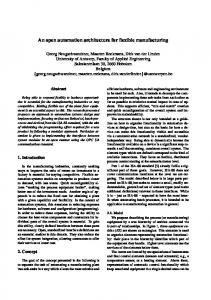
III. PROPOSED FRAMEWORK A. Network Architecture and Operating System Many wireless personal area networks (WPANs) such as Zigbee, Z-Wave, and 6LoWPAN have been emerged to support the development of home automation systems [14]. Despite the popularity of Zigbee standard in many research [7-9] and commercial systems, most of the Zigbee-based home automation systems need to spend a lot of efforts to implement a gateway between Zigbee and other IP networks. This difficulty leads to the development of Zigbee IP standards [15]. However, it is still a young standard and need much evaluation to be used in practical applications. 6LoWPAN, which is an IPv6-based WPAN standard, has emerged in 2007 [4]. By taking advantages in the ongoing transition to IPv6 of the whole IP networks, 6LoWPAN provides easy interoperability with other IPv6 networks. This means that, being an Internet protocol, 6LoWPAN does not require a license to implement. Therefore, it could reach a larger amount of audiences compare to other technologies [14]. 6LoWPAN has been receiving lots of studies and development efforts in recent years, including the RPL routing protocol published in 2012 [16] and implementations of 6LoWPAN network stacks in several open-source network operating systems such as Contiki and RIOT-OS. In this study, RIOT-OS is chosen for implementing 6LoWPAN network stacks and operating system services in our proposed framework. Compare to other open operating systems for the Internet of Things (e.g. Contiki, TinyOS), RIOT-OS provides many nice features such as support for various 32-bits ARM microcontrollers, multi-threading, real time kernel, and support for standard C and C++ programming environment [5]. Among three main architectures for 6LoWPAN [17], the ad-hoc 6LoWPAN architecture as shown in Figure 1 is adopted in our framework due to the instability of RIOTOS’s border router implementation; and the connectivity between 6LoWPAN network and other IP networks. Additionally, 6LoWPAN ad-hoc architecture could easily expand to simple architecture or extended one by connecting one or two border routers to the network as any other regular routers. Regarding this network architecture, it has two kinds of nodes: control center (CC), host boards (HBs). Multiple logical zones could be defined to represent various rooms in a house, e.g. living room, bedroom, bathroom, and kitchen. The user could easily manage devices in each logical zone. The control center is always placed in a special zone called Global zone while host boards can be placed in any other zones. The user can interact with the system over Bluetooth Low Energy (BLE) by using smart devices (e.g. Smartphones, tablets) to interact with the system via CC. Bluetooth Low Energy was chosen in our framework because it could provide fast-enough data rate (up to 1Mbps) and low latency (minimum 3ms) for a small amount of data communication (less than 1KB per transaction) within a sufficient distance (theoretically, BLE could support 60 meters or beyond) [18] while consuming less
Figure 1. Ad-hoc 6LoWPAN architecture for home automation systems
Each end-device in the network has a unique global 32bits identifier that is broken down into 16-bits Node ID, 8bits End Point ID, and 8-bits Device Type ID as shown in Figure 2. Node ID is used to identify the HB and the corresponding zone that the HB belongs to. Node ID is configured via shell command during the installation stage. Then, Node ID is used as 16-bits short address for each HB in 6LoWPAN network and together with a network prefix to form 128-bits IPv6 address. Theoretically, there are up to 256 logical zones. Each zone has up to 256 HBs, and up to 256 end-points (EPs) (i.e. maximum 256 end-devices) in each HB. The actual number of end-points in practical application is limited by HB’s free memory. These amounts of zones, HBs and EPs are sufficient for home automation systems that are used in two to three story houses.
Figure 2. Device ID format
1) Control Center Control center (CC) plays the role of a root router in the RPL routing protocol. It is the central device that holds all incoming data from other nodes. When it receives any new data from HBs, then it will send output values to the corresponding nodes based on data analysis and predefined scenarios. It also plays the role of a gateway for users to interact with end-devices/end-points inside 6LoWPAN network via Android application. 2) Host Boards To maintain cost-effectiveness of the proposed framework while harnessing processing power of modern 32-bit microcontrollers, Host Boards (HBs) are designed to be able to handle multiple end-devices simultaneously. For an example, the kitchen of a smart home has a temperature sensor, a light sensor, and an LPG (liquefied petroleum gas) sensor to measure ambient temperature, light intensity, and LPG concentrations, respectively. Beside, an alarm is also needed in case of emergency. Because most of the time spent on controlling each end-device is sleeping, these end-
devices could be grouped on only one HB with the support of multi-threading from the operating system. Therefore, the cost could be reduced while still maintaining flexibility to control and replace each end-device individually. Each HB could be the RPL host node or RPL node router that has many logical end-points (EPs), which could hold one end-device on each instance. The HB’s architecture is constructed as Figure 3.
the device list of CC. The remaining one is only used by EP to periodically advertise the aliveness of the end-devices to CC.
Figure 4. Communications diagram in the proposed framework
Figure 3. Host board architecture
Each EP hosts for one end-device of different kinds, such as LEDs, motors, sensors, and etc. As abovementioned, the maximum number of EPs in practical application is limited by HB’s free memory. In our prototype, each HB could host for 8 EPs. This means that up to eight end-devices could be placed on one HB. Each EP is implemented as a thread in the operating system (RIOT-OS). The CC and HBs in the proposed framework are implemented with low-cost microcontrollers (e.g. ARMCortex M3 microcontroller). They always contain a nonvolatile memory module, an SD-Card in FAT format, to store EPs’ configuration data, scenarios, and list of devices. Once these data change, they are updated to this non-volatile memory. This helps CC and HB to restore important data to continue functioning from their last states in case of sudden power blackout, battery problem, or accidental reset. By taking advantages of shell support in RIOS-OS, the CC and HBs always have the ability to communicate with users via any terminal emulator using UART protocol. B. Communication Models There are three categories of communications in the proposed framework as shown in Figure 4, including: (1) communication between end-points and HB; (2) communication between HB and CC; and (3) communication between CC and users via an Android App. In the proposed framework, the data centralization approach is adopted to manage the whole system. The devices’ status, scenarios, and list of functioning devices on the CC are updated and synchronized via CC. Each EP is designed to be independent from other EPs and HB. Thus, at the logical point of view, devices on EPs will communicate directly with CC. There are two types of messages defined for the communication between an EP and the CC. The first type of message is used by the CC and EP to adjust the status of a real device on EP or a device in
For communication between the CC and HBs, CC and HBs have to process every incoming message and then send an appropriate feedback. Because asynchronous communication is adopted, the transmitter does not need to wait for the acknowledgement from the receiver after sending a message. As abovementioned, the users can remotely control the devices via CC by using smart devices (e.g. Android-based devices). For the communication between the CC and Android-based devices, There are twenty kinds of messages are constructed to control end-devices, retrieve network status, customize scenarios, and configure other system properties (e.g. change/retrieve names for logical zones). C. Scenarios Every state-of-the-art home automation system provides the ability to define its behaviors through rules to achieve user’s needs. As stated in [2], most of these rules are created by system maintainers rather than by users. However, our proposed framework enables both system maintainers and users to define their own rules in different manners. The proposed framework supports many different sets of rules called scenarios that are runtime reconfigurable. A scenario is a list of rules. Each rule has one input and one output. Each input consists of one or more condition(s) and some auxiliary data. Each output has one or more action(s) and auxiliary data. Each rule is assigned a priority value. The lowest priority will be executed first. By combining these simple rules, the system can perform sophisticated tasks. For examples, the system activates the alarm at 7.00 A.M, turns on music player, and opens the window shades for sunlight at the same time; or automatically activates the watering system for plants whenever the soil is dry. Currently, there are two kinds of active scenarios in our system. The first one is default scenario that is invisible to users. This scenario can only be accessed and configured through shell commands of CC. The other one is userdefined scenario. This scenario is configurable in both graphical user interfaces of Android application and CC’s shell commands. User-defined scenario always has greater priority than default scenario. This means that actions of user-defined scenario could easily overwrite actions of default scenario when there is conflict. In practical implementation, only one user-defined scenario and one
default scenario are activated at a moment. Currently, the proposed framework does not support multiple user-defined scenarios that are activated at a moment. The scenarios processing procedure will be triggered when a message, which notifies CC to update the new status of an EP, arrives at CC. This procedure is illustrated by the flowchart shown in Figure 5.
is to perform many calculation steps. For example, many sensors in the real world are simple resistive devices such as photoresistor, thermistor, humistor, or photodiode that may generate different amounts of current in response to different environmental conditions. In either case, at first the resistance value is calculated or the current amount of voltage is measured by using a voltage dividing circuit. Then, the desired value according to sensors’ characteristics is calculated. Therefore, in these examples, at least two steps are performed together with two functions to calculate the final result. However, when these functions may be complicated, they have to be broken down into many simple steps and less complicated functions. The calculation procedure of breaking down a complicated function into multiple basic functions is depicted in Figure 7.
Figure 7. Calculate the desired result from the output of analog sensor by combining many basic functions Figure 5. Scenario processing procedure
D. Device driver layers As discussed above, in order to reduce the development efforts for many different device drivers, the object oriented approach is applied to design device driver layers for the proposed framework. Device drivers could be broken down into three simple base classes: GPIO, ADC, and PWM as shown in Figure 6. These classes served as a hardware abstraction layer that can directly access the hardware. The classes in upper layers will inherit from the lower layer classes.
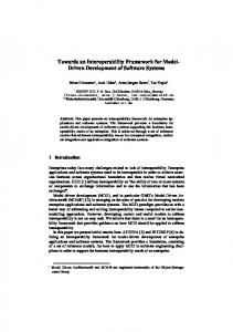
The result of a function will be the input for the next function. Then, the desired value is equal to (1). 𝑦 = 𝐹𝑛 (𝐹𝑛−1 (… (𝐹1 (𝑥)))) (1) where n is the number of basic functions and x is the output value of analog sensor measured by ADC module. For an example of calculating the desired value of a photoresistor, the schematic and characteristic of this photoresistor is shown in Figure 8.
Figure 8. Schematic (left) and characteristic (right) of a photoresisitor
Figure 6. Device driver architecture of an end-point.
Conventionally, in order to get the desired value from an analog sensor belong to the ADC sensor class, a corresponding basic function is usually adopted to the output value of sensor obtained from the ADC microcontroller’s module. However, the proposed framework supports various basic functions and provides a mechanism to combine these basic functions. Therefore, in the proposed framework, one driver class can support many different kinds of analog sensors. In practical application, an approach of combining the basic functions to get the desired result from analog sensors
From the schematic, let Rs (k ) be the resistance of the photoresistor and Vadc(V) is measured voltage by microcontroller’s ADC module, we have: 3.3 ∗ 𝑅1 1 𝑅𝑠 = − 𝑅1 (Ω) = − 1(𝑘Ω) (2) 𝑉𝑎𝑑𝑐 0.303 ∗ 𝑉𝑎𝑑𝑐 From the characteristic of this photoresistor, let L (lux) be the intensity of ambient light, we also have: 5 11 𝑙𝑜𝑔10 (𝐿) = − ∗ 𝑙𝑜𝑔10 (𝑅𝑠 ) + 4 4 2.75 −1.25 ⟺ 𝐿 = 10 ∗ 𝑅𝑠
(3)
Equation (2) and (3) combine to give: 𝐿 = 𝐹2 (𝐹1 (𝑉𝑎𝑑𝑐 )) where {
𝐹1 (𝑥) = 10 𝐹1 (𝑥) =
2.75
1 0.303∗𝑥
∗𝑥
−1.25
−1
= 562.34 ∗ 𝑥
(4) −1.25
The other classes have the similar mechanism of breaking down into simple parts, but in a simpler manner. For an example, PWM (Pulse Width Modulation) device class provides methods to configure the microcontroller’s PWM module, change duty cycle and frequency of output pulse. Straightforwardly, dimmable bulb class inherits these methods to implement its ability to change the intensity of a dimmable light. Furthermore, RGB LED class is created by combining three instances of dimmable bulb class. This class also needs a calibration procedure, which could be configured through device configuration process via shell commands, to adjust correct colors. E. Device configuration Every EP could host any end-device supported by device driver layers. The configuration is performed by describing the characteristics of a device via shell commands. These data will be saved to the file system. Then, each EP transfers these data as arguments to create appropriate instances of the device driver classes. In order to make a device work after hot-plugging it into a HB, three information are required as follows: (1) device type; (2) device function; and (3) location that the device is plugged in. By using shell commands, any device on an EP can be replaced or removed at any time without the needs of resetting or reprogramming HB. Every EP without any working device will go to sleep until it is woken up by shell commands for hosting an end-device.
B. Hardware Figure 10 shows a photograph of the board that we designed to be used in our prototype. The microcontroller board (called MBoard-1) implements one STM32F103RCT6 (ARM Cortex – M3) microcontroller with built-in 256 KB of Flash and 48 KB of RAM. Beside, CC1101 transceiver is used to communicate within 6LoWPAN network and Bluegiga’s BLE112 module provides connectivity over Bluetooth low energy protocol. Figure 10. modules
MBoard-1 with mounted CC1101 and Bluegiga's BLE112
C. Experimental results All major components of the CC and HB have been implemented and prototyped as shown in Figure 11.
IV. A PROTOTYPE OF HOME AUTOMATION SYSTEM A. Floor plan To evaluate the proposed framework, a prototype is designed and implemented. Figure 9 shows the floor plan of our home automation system. This system has four zones (except the Global zone) representing four rooms of a conventional house. They are living room, bedroom, kitchen, and garden.
Figure 11. Prototype of a home automation model
Figure 9. The floor plan of a prototype of home automation system
This prototype supports 9 types of conditions and one kind of action for each rule that are summarized as follows: Conditions The value of a device is equal to a threshold. The value of a device is less than a threshold. The value of a device is less than or equal to a threshold. The value of a device is greater than a threshold. The value of a device is greater than or equal to a threshold. The value of a device was changed. The value of a device was changed over a threshold. In a specific time period. In a specific time period every day. Action Adjust the value of an end-device. Each rule could support maximum 3 inputs and 3 outputs. Up to 25 rules are able to store in a scenario. Several rules have been set up in our prototype such as (1) the front door will open and the bulb near the front door will
turn on when someone enters the house; (2) alarm rings and some lights turn on at 7 A.M every morning; and (3) automatically activate the watering system for plants in the garden when its soil is dry. Our prototype consists of 28 end-devices of 15 different kinds. The device driver class of analog sensors supports 3 different kinds of basic functions as described in (5). Supported end-devices and their classes are summarized in TABLE I. 𝑌 = 𝑎𝑋 𝑏 + 𝑐 1 𝑌= +𝑐 𝑎𝑋 + 𝑏 𝐿𝑜𝑜𝑘𝑢𝑝 − 𝑇𝑎𝑏𝑙𝑒
(5.1) (5)
(5.2) (5.3)}
where a, b, c are constants. TABLE I. SUPPORTED END DEVICES AND THEIR CLASSES, CONVERSION FUNCTIONS, UNITS.
End-device
Class (conversion function; unit)
On/Off bulb
On/Off output (on, off and blink at 1-10 Hz)
Buzzer
On/Off output (on, off and blink at 1-10 Hz)
Switch
On/Off input (on, off)
Tactile Button
On/Off input (on, off, holding)
PIR Sensor
On/Off input (on, off)
TI’s LM35
ADC sensor (F1(x) = 100*x, where x is Vadc; oC)
TI’s LMT86
ADC sensor (F1(x) = -91.74*x + 192.94, where x is Vadc; oC)
TI’s LMT84
Photoresistor
562.34 * x
MQ-6 LPG Gas Sensor
Soil Moisture Sensor
TABLE II.
ADC sensor (F1(x) = -181.82*x + 188.18, where x is Vadc; oC). ADC sensor (F1(x) = 1.25
191374 .14 * x
2.5
Option(s)
senadc
-e [EP_id] -s [sensing condition] -p [port] -n [pin] -a [adc] -c [channel] -t [equations] -P [parameters] -f [noise filtering value] -u [alert under bound] -o [alert upper bound]
rgb
-e [EP_id] -R [port] [pin] [timer] [channel] -G [port] [pin] [timer] [channel] -B [port] [pin] [timer] [channel] –C [calibration data]
1 20 , F2(x) = 0.303* x
-s [d or u], select default or user’s activated scenario.
; ppm)
-l, show a scenario.
1 ADC sensor (F1(x)= 1 , 0.303* x
F2(x) = Lookup-table; where 1.32 is average value for “in water”, 2.86 is “wet”, 26.4 is “dry”)
Dimmer
ADC devices (0 – 100 %)
Dimmable Bulb
PWM devices (0 – 100% and blink at 1-10 Hz)
RGB LEDs
PWM devices (15 bit RGB color)
SG90 Servo Motor
PWM devices (0o – 180o)
SHELL COMMANDS FOR MANAGING ANALOG SENSORS, RGB LEDS, AND SCENARIOS.
Command
1 1 , F2(x) = 0.303* x
; lux)
ADC sensor (F1(x) =
Over 20 shell commands have been implemented to manage and configure the network, file system, end devices, and scenarios. TABLE II summarizes current shell commands in our prototype for managing analog sensors, RGB LEDs, and scenarios. For an example, the following shell command is to create a new ambient light sensing device using a photoresistor, which has been recently mentioned. The newly created device will be placed on EP #5, port C, pin #3, channel #13 of ADC #1. senadc –e 5 –s 2 –p c –n 3 –a 1 –c 13 –t r p –P 0.303 0 -1 562.34 -1.25 0 –f 50 –u 50 –o 5000 The name of the command (senadc) means that an analog sensor will be created. –s 2 shows that it is an ambient light sensor and its unit is lux. –t r p tells the system of HB that the functions used to convert the measured voltage by ADC module (Vadc) to the final result are broken down into two basic functions. The parameter r means that the first one is a rational function (i.e. F1(x) = 1 / (a*x + b) + c) and with parameter p we will have a polynomial function as the second one (i.e. F2 = m*xn + p). Option –P supplies these two functions with parameters (0.303 0 -1 562.34 -1.25 0), which are a, b, c, m, n, p respectively, according to (4). Lastly, –f 50 –u 50 –o 5000 are parameters for filtering out the noises, under and upper bound to trigger an alert, which will make an EP to immediately send a message containing the new value to the CC instead of sending an average one at the end of each measuring cycle.
–a [index] –i [condition and data] –o [action and data], add new rule to a scenario. Multiple –i and –o options are allowed. -d [index], delete a rule. scene
-p, pause scenario processing procedure. -r, restart scenario processing procedure. -v, save a scenario to file. -e, restore a scenario from file -n [old name] [new name], rename an inactive scenario. -h, show usage. Multiple options could be combined together.
Each EP in our prototype consumes 1.2 KB of RAM and up to 8 EPs that are supported on each HB. The other RAM resources are consumed by RIOT-OS’s network stack (~30KB) and auxiliary codes. When the output power is set to 0 dB, the average communication distance for devices in 6LoWPAN and BLE network is around 25 meters within an indoor environment. An Android application enables user to remotely manage the system. The left screenshot in Figure 12 shows the device control tab that enables user to monitor current devices’ status in the network; control end-devices remotely; and edit zones’ name. The right screenshot shows scenario customization tab that enables user to customize (e.g. add, delete, and edit) rules and activate scenarios.
[2]
[3]
[4]
[5]
[6] [7]
[8]
[9]
[10]
[11] Figure 12. Devices control tab (left) and scenarios customization tab (right)
The latest workable source code and design files of our prototype are published under GNU LGPL v2. 1 license at https://github.com/dangnhat/HA-project/. V. CONCLUSIONS In this paper, we propose a framework for developing a home automation system based on 6LoWPAN. Since the proposed framework is runtime reconfigurable, it is advantageous to reconfigure the system without any needs of system reprogramming or resetting. Furthermore, the device driver layer in the proposed framework is more adaptable to various types of end-devices than the other conventional systems. Therefore, the proposed framework helps developers to reduce effort in terms of system development and maintenance. A prototype is also developed to evaluate the robustness of our framework. Further issues, including optimization of power consumption, memory efficiency, privacy and security are needed to consider in order to apply the proposed framework in practical applications. REFERENCES [1]
H. Sundmaeker, P. Guillemin, P. Friess, and S. WoelfflÌ©, Eds., “Vision and challenges for realising the Internet of Things”. Cluster of European Research Projects on the Internet of Things, European Commision, 2010.
[12]
[13] [14]
[15]
[16]
[17] [18]
[19]
[20]
M. Gamba, A. Gonella and C. Palazzi, “Design Issues and Solution in a Modern Home automation System”, in 2015 International Workshop on Networking Issues in Multimedia Entertainment, ICNC Workshop, Garden Grove, CA, 2015, pp. 1111 - 1115. A. Musa Efendi, S. Oh and D. Choi, “6LoWPAN-based Wireless Home automation: From Secure System Development to Building Energy Management”, Smart Computing Review, vol. 3, no. 2, pp. 123 - 138, 2013. J. Hui and P. Thubert, “Compression Format for IPv6 Datagrams over IEEE 802.15.4-Based Networks,” RFC 6282 (Proposed Standard), Internet Engineering Task Force, Sep. 2011. [Online]. Available: http://www.ietf.org/rfc/rfc6282. Oliver Hahm, Emmanuel Baccelli, Mesut Günes, Matthias Wählisch, Thomas C. Schmidt, “RIOT OS: Towards an OS for the Internet of Things,” in Proceedings of the 32nd IEEE International Conference on Computer Communications (INFOCOM), Poster Session, April 2013. “RIOT Operating System,” [Online]. Available: http://www.riotos.org/ K. Gill, S. Yang, F. Yao, X. Lu, “A ZigBee-Based Home automation System”, in IEEE Transactions on Consumer Electronics 55(2), May 2009. F. Domínguez, A. Touhafi, J. Tiete, M. Güler, and K. Steenhaut, "Migration from a Legacy Wireless Technology to ZigBee for a Home automation Market Ready System," in Proceedings of the 9th International Conference on Networked Sensing Systems, Antwerpen, 2012, pp. 1-4. Y. Li, J. Maorong and G. Zhenru, “Design of Home automationSystem based on ZigBee Wireless Sensor Network”, 1st IEEE International Conference on Information Science and Engineering(ICISE) 2009, pp. 2610-2613, 26-28 Dec. 2009. N. Sriskanthan, F. Tan, and A. Karande, “Bluetooth based home automation system”, Microprocessors and Microsystems, vol. 26, no. 6,pp. 281-289, 2002. A. Gurek, C. Gur, C. Gurakin, M. Akdeniz, S. K. Metin, and I. Korkmaz, "An Android based home automation system", in High Capacity Optical Networks and Enabling Technologies (HONETCNS), 2013 10th International Conference on, 2013, pp. 121-125. J. Han, J. Yun, J. Jang and K. Park, “User-friendly home automation based on 3D virtual world”, IEEE Transactions on Consumer Electronics, vol. 56, no. 3, pp. 1843-1847, 2010. Digi, “XBee/RF solutions”. [Online]. Available: http://www.digi.com/lp/xbee/. [Accessed: 24- Aug- 2015]. C. Gomez and J. Paradells, “Wireless Home automation Networks: A Survey of Architectures and Technologies”, IEEE Communications Magazine June 2010, vol. 48, no. 6, pp. 92 - 101, 2010. Zigbee Alliance, “ZigBee IP and 920IP”, 2015. [Online]. Available: http://www.zigbee.org/zigbee-for-developers/networkspecifications/zigbeeip/. T. Winter, P. Thubert, J. Hui, R. Kelsey, P. Levis, K. Pister, R. Struik, and JP. Vasseur, “RPL: IPv6 Routing Protocol for LowPower and Lossy Networks” RFC 6550 (Proposed Standard), Internet Engineering Task Force, Mar. 2012. [Online]. Available: https://tools.ietf.org/html/rfc6550. Z. Shelby and C. Bormann, “6LoWPAN: The Wireless Embedded Internet.”: John Wiley & Sons Ltd, 2009.p.13 – p.15. Bluetooth.com, “The Low Energy Technology Behind Bluetooth Smart”, 2015. [Online]. Available: http://www.bluetooth.com/Pages/low-energy-tech-info.aspx. [Accessed: 07- Sep- 2015]. Bluetooth.com, “Mobile Telephony Market”, 2015. [Online]. Available: http://www.bluetooth.com/Pages/Mobile-TelephonyMarket.aspx. [Accessed: 07- Sep- 2015]. Mouser.com, “Mouser Electronics - Electronic Components Distributor”, 2015. [Online]. Available: http://www.mouser.com/. [Accessed: 07- Sep- 2015].