retrofitting, the production system hardly stops for maintenance activities, so it is ..... [CK1] Chiron F. and Kouiss K., Design of IEC 611313 function blocks using ...
Proceedings of IDMME - Virtual Concept 2008 Beijing, China, October 8 – 10, 2008
Original Article
Towards Automation Component Based Design Hands-on Training A. Lelevé, M. Guillemot, N. Fakhfakh, D. Noterman
1- Introduction
Dr
Université de Lyon INSALyon, LIESP, F69621, Villeurbanne, France +33(0)4.72.43.60.47 / +33(0)4.72.43.85.38 Email : {arnaud.leleve , mady.guillemot, nabil.fakhfakh, didier.noterman}@insalyon.fr Abstract: Automation world is living a change of design This paper presents three handson answers to this industrial methodologies. Old topdown approaches are being replaced evolution: the design of a ventilation system, a sequential by component based design allowing design, realization and gearbox and an elevator. These three samples introduce exploitation cost gains. Automation training in universities also component based design and appeal to simulation of parts of evolves in order to train future automation industrialists up to the studied systems. The gearbox and the elevator handson date on new design paradigms and technologies. This paper resources are available on AIPPrimecaRAO remote presents three projects illustrating this evolution, based on laboratory platform1. The remainder of this paper is training component based design applied to simulation of structured as follows : we present at first this industrial evolution. This is followed by details on the use of operative and control parts use. simulation in automation. Next, we depict these three Key words: Automation, component based design, UML, samples and finally, we discuss this evolution and describe operative part simulation future directions for this work.
Nowadays, a modern automated system is a networked distributed control system featuring intelligent components (sensors, preactuators, networks, ...). Thus, their design methodologies incline towards approaches which reduce design and coding time, allow reusability of parts of programs and enable capitalizing on knowhows. These approaches are based on Object Oriented paradigm inspired from computer scientists. Design modeling languages based on UML, yet used for realtime and embedded systems, now become used in automation world to model factory automated systems.
2- Automated Production System Design
aft
Nowadays, design methodologies used traditionally by automation experts are evolving towards approaches which reduce design and coding time, allow reusability of parts of programs and enable capitalizing on knowhows. Indeed, traditional methodologies lead to monolithic hardly reconfigurable and modifiable control systems, while modern systems are organized as Distributed Control Systems (DCS) leaning on industrial field networks hosting (more and more) intelligent (able to talk directly on a field bus, to self diagnose, to be autonomous, ... according to the component) This little revolution also affects how automation is taught in sensors, preactuators, motion drivers, business specific universities. As this technical discipline is largely taught by components, ... means of hands-on sessions, corresponding hands-on trainings have to be updated with recent hardware, field buses, modern programming software, ... designed with these new 2.1 Chronology of an automation project approaches. As every french educational institute can not afford industrial up to date equipment to train their teachers Whether top-down or a bottom-up methodology is used, an and students on, these resources have been shared in a country- automation project follows a lifecycle modeled on the Vwide network of workshops : AIP-Primeca. AIPs provide, cycle used by computer scientists (except in more recent among other services, hands-on resources to train people methodologies such as eXtrem Programming, Value Based (teachers, students, industrialists, ...) on automated production Software Engineering... [B1]). This latter : systems (design, use, maintenance, ...). These resources are starts from global specifications and refine them available locally in each center (and also remotely through (detailed specifications), Internet, as for ARI project presented in [CG1]). Nevertheless, designs the software (in two steps: general and then sharing heavy systems has constraints that operative and detailed design), control part simulation modern techniques can bypass to help codes it, in providing the best service to universities. 1 See http://aipportail.insa-lyon.fr:8085/aiprao/index.html
P150
-1-
Copyright of IDMME - Virtual Concept
Proceedings of IDMME - Virtual Concept 2008 Beijing, China, October 8 – 10, 2008
Original Article
new application requires to reiterate the whole study. So there is no reusability. Moreover, this approach favors control structuring but neglects other facets of the study (electrical wiring, mechanical and energy study, Human Automation projects use the same global chronology. The Machine Interactions, ...) and its exploitation (supervision, difference is one has to design (and then to make) operative alarm management, ...). part and control part simultaneously. Compared to traditional automated systems, modern ones include Human Machine Interactions and communication with higher level software 2.3 Component-Based approach (Manufacturing Execution System, Enterprise Resource Nowadays, design methodology used traditionally by Planner, Maintenance Management Softwares, ...). automation experts is evolving towards an approach which : reduces design and coding time, allows reusability of parts of programs and, enables capitalizing on knowhows.
tests it, integrates it in production environment, validates it in production mode.
This new approach is based on Object Oriented (OO) software paradigm. It keeps a part of its interesting properties: class and object notion, encapsulation, aggregation). But it leaves apart more evolved properties: heritage and polymorphism. Recent new standards such as the IEC 61499 open standard for distributed control and automation reflect this trend [HF1]. In automation, the term “Component” is used in place of “Class” as it features more information and process than simply programming data and methods.
Dr
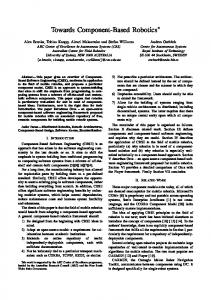
Figure 1: traditional AutomationV Cycle
Automation Component Based Approach [J1, T2] leans on a methodology structuring an equipment in operative subsets. Traditional tools of functional analysis used by automation This analysis is realized according to two complementary dimensions designers are axed on a logic of specification defining : functioning modes, the physical dimension, anomalies and their treatment, the functional dimension. 2.2 Classical design methodology
aft
The most popular tool in France (which is even more popular in universities than in industry) is the GEMMA which is a study guide of run and stop functioning modes. It has been developed by ADEPA which is a national agency which aims at developing applied industrial engineering. The GEMMA consists in a graphical analysis procedure enabling to determine different functioning modes and paths and conditions to pass from a mode to another one. This generic diagram is generally a preliminary step before elaboration of functional specification using IEC 60848 GRAFCET charts (which were preliminary designed to be a specification tool and has become a programming language ; more recent IEC 61131 Sequential Functional Chart (SFC) is only a programming language). Then follows the coding in one out of the four IEC 61131 standard languages (Ladder Diagram, Structured Text, Function Block Diagram and Instruction List). This top-down approach leads to a hierarchical control structure characterized by: a synthetic representation which facilitates comprehension and application analysis, a great efficiency and a quick startup and easy maintenance. However, every analysis is dedicated to a new system and a
P150
-2-
An automation component is representative as well of an operative part of an equipment to be automated (associated actuators and sensors) as a functional control module [BG1]. Moreover, an automation component is relatively generic (it can be imported from a standard or a specific library). It is then later directly instanciated (as many times as necessary) in an application or specialized (and then instanciated). It answers to two main needs: reusability :which enables capitalizing know-how, structuration which complements topdown traditional approaches by bottomup ones. Automation Components are autonomous in a functional point of view and multifacets (it features, for instance, part list, electrical wiring plans, mechanical plans, Human Machine Interactions, maintenance procedures, ...). Each newly designed set of business components is to be recorded and administered in a library which is enriched as needs and studies go on. This perpetual recording participates in know how capitalization. The versioning of recorded components can be managed through a Product Lifecycle Management (PLM) software, for instance. As in OO approach, a component is specified (as a class) by
Copyright of IDMME - Virtual Concept
Proceedings of IDMME - Virtual Concept 2008 Beijing, China, October 8 – 10, 2008
Original Article
a set of parameters, inputs, outputs and a specific program linking the whole to create the research behavior (see last section for samples). Its instances (objects) will share the same properties, same behaviors and same semantics but they will each one live their own life according to the way they are stimulated [VH1]. One can find in these methods: a static aspect which describes an object characteristics and its links with other objects, a functional aspect which defines its method behaviors a dynamical aspect which describes interactions between objects and the different states which every object can be in.
Standards
Even if UML was at first targeted towards pure computer science projects, its popularity and genericity have rapidly seduced designers for real-time systems [OM1], embedded systems [AF1], mechatronic systems [BG2] and then automated systems [KN1, RK1, OM2].
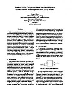
Prototypers Prototype component Library
Administrator Validated Component Library
2-5 Training on automation design
The evolution of these methodologies requires to keep university and technical college teachers up to date so that they can train efficiently students who will have to use them later in industry.
aft
Know-how Capitalizing
Business Specifiers
To train teachers and then students to these new methodologies, as for many technical disciplines, it is most efficient to illustrate typical usecases by handson trainings on manufacturing equipments [FI1]. But such resources are few and their availability, linked to platform office opening hours, is an obstacle to their use in lifelong training as well as with an international audience.
Application Architect Project
Figure 2: future automation component life cycle ?
2-4 UML modelling in Automation
As automated system design is moving from document centric to model centric, modeling languages such as UML become available to automation designers [SD1]. UML (Unified Modeling Language) is a graphical language modeling data and process. It is an open formalism very accomplished for object oriented modeling broadly used in software engineering. UML does not define model elaboration process : it is not a methodology nor a toolbox, uniquely a graphical modeling language. In 2003 the Object, Management Group (OMG) released the version 2.0 of the UML. UML2 defines thirteen
P150
The strength of UML2 is that it becomes possible to create profiles for specific business fields. Profiles are both specializations of UML2 generic diagrams and extensions of initial formalism, in order to specify clearer behaviors (in each business field), such as OMG SysML [OM2, CK1]. SysML aims to support the specification, analysis, design, verification, and validation of systems that include hardware, software, data, people, procedures, and facilities.
Dr
This new way of programming has modified project organization. New businesses appear : business specifiers : design standard components, their facets (programming interface (inputs/outputs/parameters), HMI widgets, electrical and mechanical models and constraints, part list, network configuration, ...),, their data structure and interfaces, prototypers : make every facet of standard components, test each unit, component administrators : manage component structure rules, program and electrical wiring plan generation, documentation, validation cycles, application architects : reuse standard and business components to integrate them into a global application which they finally validate.
diagrams which use is free according to one's appreciation [BR1]. UML software modeling is lead according to three points of view which appeal to some of the 13 diagrams: functional point of view : use-case diagram static point of view : class diagram dynamical point of view : state diagrams, sequence diagrams.
-3-
But, every educational institute can not afford industrial up to date equipment to train their teachers and students on. This is why, in France, these resources are shared from a country-wide network of workshops : AIP-Primeca The A.I.P. (Inter-Establishment Production Engineering Workshops) are regional resource centers, created in 1984, and used as support for high-level training in the Industrial Automation field. AIP-PRIMECA (Computing Resource Centers for Mechanical Engineering) were created in 1991 to promote the use of computing tools in the design of mechanical products and establish training programs in Computer-Aided Mechanical Design. Its missions, alloted by the french education ministry concern: initial learning, life long learning, technological transfer (from research laboratories to industry), knowledge diffusion (towards universities and industries).
Copyright of IDMME - Virtual Concept
Proceedings of IDMME - Virtual Concept 2008 Beijing, China, October 8 – 10, 2008
Original Article
Dr
Out of ten regional clusters, AIP-Primeca-RAO (Rhone Alpes when it is not possible to work on it remotely by West) is a resource for various high schools in french Rhôneway of a remote laboratory platform, it is only Alpes Region. Its eight partner universities are also its main available at office opening hours. users, in : Lyon (INSA, Ecole Centrale, Université Claude 3.3 Advantages of appealing to simulation: Bernard Lyon 1, ECAM, IUT Lumière of University A solution to these constraints is both industrial and Lyon 2), SaintEtienne (ENI, Ecole des Mines, Université Jean educative contexts is to appeal to software simulation of Operative Part. Its advantages are : Monnet SaintEtienne). this solution is cheaper than real heavy hardware so there is no heavy investment in specialized The resources at users' disposal are mainly composed of : machines, industrial equipment (such as CNC machine-tool, the material quantity is infinite, conveyors, assembly automation systems, robots, ...), the simulator is always available and it can be run, computer systems featuring industrial software independently in parallel on several desktops, (Computer Aided Design (CAD), Computer Aided it can be done anywhere as soon as one owns the Manufacturing (CAM), Manufacturing Execution simulation application, System (MES), process simulation, shop control, ...), no human and hardware risk of loss or destruction, communication and cooperation systems (LAN, WAN possibility to reduce the complexity of the situation access, videocommunication, Computer Supported to focus testing on specific aspects (and limiting Cooperative Work (CSCW), ...). blockings hazards), possibility to enrich information picked up from the Concerning this paper topic, AIP-Primeca-RAO has been system (modifying spacial and timing parameters, proposing resources for automation hands-on training as a displaying normally invisible informations and local usage in its buildings (and also remotely through Internet mechanisms, infinite replay...). [CG1]).
3.1- Industrial needs
aft
Today, RAO works on the “Collaborative Enterprise” and the “Product Lifecycle Managament” (PLM). These topics include Moreover, in educational context: the absence of risk enables making this educational the “Collaborative Design” and the Automated Production resource in self service, System Building. this solution can be relatively easily proposed remotely as a virtual laboratory, which answers needs of scalability and raises opening time to 24h/24h, 3- Operative Part Simulation Nevertheless, simulation is always based on a model which represents reality with a certain degree of approximation. The more the model is realistic (taking into account frictions, environmental perturbations, ...), the more it is heavy and difficult to design and run. Also, software simulation mainly requires abstraction : no touch, no smell, no taste, ... Every return of information from the system is transmitted by vision (2D or 3D) and in some cases by haptic return (returned efforts on a joystick) [CN1].
In Automated System design, programming requires testing on the real system. This involves: to have access to the target system (in case of retrofitting, the production system hardly stops for maintenance activities, so it is not available for programming tests), that its prohibitive cost generally prevents from creating a clone just for testing, 3.4 How Simulation is used that test can be destructive so very risked for hardware and also possibly for surrounding people, Typical industrial use of operative part simulation is when when several systems are embedded, it is difficult to testing one's program before uploading it on the real system. isolate one to test it without making trouble with others. It can be used in various educative situation : in courses, to illustrate phenomenons 3.2 Educational needs in exercises, to accompany students in their learning in virtual laboratories In a educational context, more constraints appear: in remote laboratories before testing programs on potentially destructive tests should not hurt anybody real shared systems nor destroy educative hardware where students are people who are not experts of systems and 3.5 How Simulation is done opportunities to break it are more present, industrial hardware is very expensive so very few Simulating operative part can be done either by specific apparatuses are available for a growing number of softwares programmed commonly in C or VisualBasic students, moreover through remote laboratories, languages; possibly on a real-time system.
P150
-4-
Copyright of IDMME - Virtual Concept
Proceedings of IDMME - Virtual Concept 2008 Beijing, China, October 8 – 10, 2008
Original Article
It may be also done by means of scientific software such as they have had to make hybrid simulations where : MathWorks MATLAB+Simulink and more likely (in one part of the operative part is real: two motors, automation area) by National Instruments LabVIEW. one controlled by a motor starter and the other one Another approach consists in reusing automation software such by a motion driver, the other part is virtual: it consists of models as supervision ones which are more likely to communicate with Programmable Logic Controllers (PLC) and can be more designed and run in the PLC in order to simulate the easily (generally graphically) programmed than in rest of the operative part. C/VisualBasic. A last solution consists in appealing to specialized simulation Component Based Design has been used. Some basic software, such as Geensys ControlBuild. components (one interfacing a cylinder and the other simulating it) had been provided in a tutorial. Students could Nowadays, main automation suppliers propose software reuse them as is and modify them when necessary. simulators which simulate a control part: their PLCs can so be emulated by a PC. For instance, Schneider Electric Unity To illustrate this application, we present one out of these enables simulating the target PLC in the development stage. projects, which consists in managing the ventilation of an Geensys ControlBuild enables to simulate both Control Part industrial system which temperature has to be controlled. (the PLCs) and Operative Part. An hybrid simulation can be This system is depicted in figure 3. It consists of a fan which created with certain parts of both parts which are simulated and requires to be lubricated. A lubrication circuit must be started others which are the real ones. before turning the fan. A control law is designed to set the fan speed at the right value according to the tank desired Moreover, the standardization of field bus communication over temperature. Ethernet enable to easily simulate both operative and control parts on one or several networked PCs.
Dr
3.6 Educational use
aft
In education context, resorting to simulation brings numerous important advantages. It can be used: to dynamically illustrate a course, to enhance interactivity of classroom exercises, in local laboratories to replace part or all apparatuses, in remote laboratories to compensate for the difficulties due to the remote handling. This is partly why first implementations of distant handson laboratories were based on simulations [CN1].
Figure 3: ventilation system to control and simulate
In development phase, students use a PLC simulator (provided by Unity Pro) which enables to debug without constraints of apparatus busy planning. In this phase, they 4- Three incremental approaches have to design a whole simulated operative part. These two We propose in this section to illustrate previous discussions parts are split into different sections in order to disable the with three educational projects aiming at training students on simulation sections earlier. automation component design with support of UML diagrams. First one uses a PLC to simulate lacking operative part In the test phase, they have access to real apparatuses. In this phase : components. Second and third ones use a supervision software the fan is simulated by a real motor controlled by a to simulate operative part. motion controller, the pump is simulated by a motor fitted with a motor starter, 4.1- Industrial ventilation project the gates and the model of the system to cool remain software simulated (the temperature evolves Since 2007, students of Industrial Engineering at INSA Lyon according to the speed) : see fig. 4. have been given a new automation platform for hands-on training [CG1] featuring real PLCs, electric motors, motion drivers, ... In this project, nine groups of students had to work One real PLC hosts the control part and the software on the design of an automated global system. They had access simulated operative parts. to the apparatuses during three sessions of 4h each. They used this time to get used with the development software Unity Pro and to test their programs. As apparatus sets are generic (1 PLC, 1 field network (Modbus, Profibus, CANOpen, AsI, Ethernet), 1 motion driver, 1 motor starter and two motors),
P150
-5-
Copyright of IDMME - Virtual Concept
Proceedings of IDMME - Virtual Concept 2008 Beijing, China, October 8 – 10, 2008
Original Article
Figure 4: ventilation system components
The liveliness is obtained by way of scripts written in JAVA which are associated with graphical objects. Simulation facet is realized and integrated into a component library. Basic components can then be put together in order to create more complex components such as double tandem cylinders with their own sensors and transducers. Global system is architectured on Ethernet network at high level (PLC – HMI panel – programming computer) and CANOpen for low level communication (PLC – Motion driver – networked cylinder distributors).
Dr
In this case, the programming of a few real systems enabled students to deal with real industrial systems. The low number of real apparatuses was compensated by the use of simulation. The restricted time (3x4h) given to learn how to use available softwares, to resolve attributed problem and to test it is actually borderline. Four supplementary hours are necessary for students to finish correctly their work. Sixteen supplementary hours would have been necessary without simulation features. Moreover, the fact that the simulator is integrated into the development software made things easier for students as they had not to learn different dedicated softwares.
Figure 5: sequence diagram corresponding to a gear change.
4.2- Sequential gearbox control
aft
This project concerns on-board control of a mechatronic system which study can be approached in different ways: by a whole simulation. It can be used as a pedagogical support to a case study in exercises, by a real system dealing with technological aspects : featuring a PLC, preactuators (motion control, pneumatical distributors), actuators (electrical motor, pneumatical cylinders) field network (CANOpen), HumanMachine Interface (HMI). In local or remore laboratories, a test system with the real gear box is available.
Whatever approach, a functional study is led through UML Figure 6: screenshot of the simulated operative part diagrams conforming to previously exposed methodology. Figure 5 shows a sequence diagram corresponding to gear In this project, simulation was necessary for students in order changes. to test their program before applying it on the real system. In In the case of a global simulation, a single PC computer the previously introduced project, the system could not be broken as there was just one or two rotating independent axes enables : to emulate control part (in the Schneider Electric per system. In this project, actuating cylinders have to be coordinated to engage the good gear. If students make programming software Unity Pro), to simulate the operative part (in the HMI emulator mistakes in this movement, pieces of the gear box may brake featured by Schneider Electric HMI programming themselves. Moreover, if students engage wrong gears (5th gear to first one in place of 4th one), this may also break software Vijeo-Designer). pieces as in a real car, even if lower speeds are used in this system.
P150
-6-
Copyright of IDMME - Virtual Concept
Proceedings of IDMME - Virtual Concept 2008 Beijing, China, October 8 – 10, 2008
Original Article
Figure 7: gearbox system architecture
4.3- Elevator
In this application, the study focuses on the functional division of an elevator. This elevator is composed of : a lift shaft including conductor rails, electric wires and sensors, a cabin featuring a set of indoor doors and an HMI panel, a machinery moving the cabin.
(resp. operative) part of an internal door is modeled, students (resp. tutors) can use this model for elevators with two internal doors. Thus, a tutor can prepare a model of the operative part for an elevator with an arbitrary number of floors and then make students design neatly their control model. The second part of the exercise consists in asking to students for a control model of a slightly different operative part. Good models would require very few adjustments to fit the new operative part. This level of freedom would be difficult to obtain with a scale model. Experience shows that students would have opted for a traditional way of programming as they work on a frozen configuration and then to fiddle it to fit the second configuration, with some difficulties and much more time. The gearbox and the elevator handson resources are available on AIPPrimecaRAO remote laboratory platform2. Development softwares are available online and students can use them exactly as if they were in situ.
aft
Dr
The analysis enables to create a library of elementary components required for the control. These components are designed as Derived Function Blocks (DFB) : door component dealing with opening and closing of doors, winch component controlling cabin moves, call priority management dealing with calls from people at different floors waiting for the cabin and the people inside the cabin. These three DFB are then put together in a new component dealing with the control of a whole elevator. Once the elevator DFB checked, it can be used in many situations and coding time will then be much decreased compared to a new study. This new DFB can then be instanciated several times to control several synchronized elevators. Concerning operative part simulation, a 2 cabin elevator simulator has been developed by using Vijeo Designer, such as for the previous gear box. This model is based on two instances of a component simulating operative parts for a single cabin. Figure 8 is a screen shot of the resulting HMI. This simulator enables user to drive the elevators by mean of indoor keyboards and call buttons on each floor. Security behaviors can be simulated such as people preventing the closing of doors or overweight in case of too many people getting inside the cabin.
Figure 8: double cabin elevator HMI
5- Conclusion
Nowadays, design methodologies used traditionally by automation experts are evolving towards approaches which reduce design and coding time, allow reusability of parts of programs and enable capitalizing on knowhows. This paper summed up main aspects of this evolution from an industrial point of view and more accurately on an educational point of view. Component Based Design associated with UML (or a specific profile) are becoming the way to design factory automation systems. Along this evolution, computer tools also evolve and operative and control part simulations are now integrated in automation programming suites. This is why educative institutes are also evolving in order to produce future automation experts up to date on today design methodologies, tools and technologies. Three samples were presented involving the use of simulation of part or whole of
This project aims at illustrating the advantages of Component Based Programming towards students. Indeed, as soon as a floor control (resp. operative part) model is validated (featuring the control of external doors, call buttons, external display, ...), students (resp. tutors) just have to instantiate it as times as necessary to create a control model for a whole elevator covering several floors. In the same way, as soon as the control 2 See http://aipportail.insa-lyon.fr:8085/aiprao/index.html
P150
-7-
Copyright of IDMME - Virtual Concept
Proceedings of IDMME - Virtual Concept 2008 Beijing, China, October 8 – 10, 2008
Original Article
the operative and control part.
in Undergraduate Engineering Education, In Journal of Engineering Education, pp 121-130, January 2005.
As this evolution progressively leads to new businesses (business component furnisher, component library manager), universities will have to prepare their students to these skills. We are working on hands-on training projects delimiting each role in the automated system design chronology to help students to build skills in each design step.
[HF1] Hussain T. and Frey G., Migration of a PLC Controller to an IEC 61499 Compliant Distributed Control System: Handson Experiences, In Proceedings of the IEEE International Conference on Robotics and Automation (ICRA 2005), 1822 April 2005, pp. 39843989, 2005
[J1] Jeong, H., Interactive Technologies and Sociotechnical Systems, The Component Based Factory Automation Control [AF1] Agnès M., Frati P., André C., Rigault J.P., UML et le in the Internet Environment, Springer Berlin / Heidelberg, paradigme synchrone : application à la conception de pp. 290299, 2006. contrôleurs embarqués, In SPORTS Project Report, [KN1] Köhler Hans J., Nickel U., Niere J., Zündorf A., http://www.i3s.unice.fr/%7Emh/RR/2002/RR02.02 Integrating UML Diagrams for Production Control Systems, C.ANDRE.pdf, february 2002. In Proceedings of the 22nd IEEE International Conference on [B1] Boehm B., A view of 20th and 21st century software Software Engineering (ICSE'00), ISBN:1581132069, engineering, In Proceedings of the 28th international Limerick, Ireland, pp. 241 – 251, June 411, 2000. 6- References
conference on Software engineering, Shanghai, China, Pages: [OM1] Object Management Group, UML Profile for 12 – 29, 2006 Schedulability, Performance and Time Specification, Version [BG1] Buckley J., LeGear A. P., Exton C., Cadogan R., 1.1, 2005
Dr
Johnston T., Looby B., Koschke R., Encapsulating targeted component abstractions using software Reflexing Modelling, [OM2] Object Management Group, OMG System Modelling In Journal of software maintenance and evolution, 20(2), pp. Langage (SysML) Specification, Final Adopted Specification, ptc/20060504. 107–134, march 2008. [RK1] Ritala T., Kuikka S., UML Automation Profile: Enhacing the Efficiency of Software Development in the Automation Industry, In Proc. of 5th Int. IEEE Conf. on Industrial Informatics (INDIN 2007), Vienna, Austria, July 2326, 2007
[CK1] Chiron F. and Kouiss K., Design of IEC 611313 function blocks using SysML, In Proc of Mediterranean Conference on Control & Automation (MED '07), 2729 June 2007, Athens, Greece, pp. 15, ISBN: 9781424412822, doi 10.1109/MED.2007.4433695, 2007
[VH1] Vyatkin V., Hanisch H. M., Reuse of Components in Formal Modeling and Verification of Distributed Control Systems, In Proc. of 10th IEEE International Conference on Emerging Technologies and Factory Automation, (ETFA 2005), Catania Italy, September 19 22, 2005, pp 129 134.
aft
[BG2] Burmester S., Giese H., and Tichy M., Model-Driven Development of Reconfigurable Mechatronic Systems with Mechatronic UML, In Model Driven Architecture: Foundations and Applications, LNCS 3599, (ed.) Springer Berlin/Heidelberg, pp. 47-61. Springer-Verlag, doi 10.1007/11538097_4, ISSN 0302-9743 (Print) 1611-3349 (Online), august 2005.
[SD1] Servat D., Chiron F., Kouiss K., Meurisse T., Souchet G., CLIPS: experiments on modeldriven engineering for [BR1] Booch G., Rumbaugh J., Jacobson I., The Unified production systems, In Proc. of 10th IEEE Conference on Modeling Language User Guide (2nd Edition), The Addison Emerging Technologies and Factory Automation (ETFA Wesley Object Technology Series 2005), 1922 Sept. 2005, Catania, Italy, ISBN: 0780394011, doi 10.1109/ETFA.2005.1612563, pp. [CG1] Coquard P., Guillemot M., Leleve A., Noterman N. and 482489, 2005. Benmohamed H., AIPPrimeca RAO Remote Laboratories in Automation, In International journal of online engineering, [T2] Trkaj, K., Users introduce component based automation http://www.ijoe.org/ojs/viewarticle.php? solutions, In Computing & Control Engineering Journal, id=206&layout=abstract, 4(1), 2008 15(6), pp. 32 – 37, Dec. 2004Jan. 2005
[CN1] Corter J. E., Nickerson J. V., Esche S. K., Chassapis C.; Im S. & Ma J, Constructing reality: A study of remote, handson, and simulated laboratories, In ACM Trans. Comput. Hum. Interact., 14(7), ACM, 2007 [FI1] Fiesel L. D. and Rosa A. J., The Role of the Laboratory
P150
-8-
Copyright of IDMME - Virtual Concept