Dec 21, 2016 - phases, i.e., the aggregates, a cementitious binding matrix ... cementitious materials using phase-field modeling are reported in [35, 36], while ...
RILEM Technical Letters (2016) 1: 94 – 101 DOI: http://dx.doi.org/10.21809/rilemtechlett.2016.21
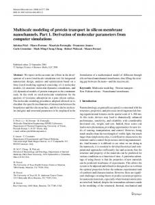
Towards multiscale modeling of the interaction between transport and fracture in concrete Pietro Carraraa*, Tao Wua, Roland Krusea, Laura De Lorenzisa a
Technische Universität Braunschweig, Institute of Applied Mechanics, Bienroder Weg 87, 38106 Braunschweig, Germany
Received: 6 December 2016 / Accepted: 19 December 2016 / Published online: 21 December 2016 © The Author(s) 2016. This article is published with open access.
Abstract Transport, fracture and their interaction in concrete are complex phenomena of great practical relevance for the durability of civil engineering structures. Due to the heterogeneous nature of the materials, encompassing a wide range of length scales, multiscale approaches are essential. In this paper, we outline some recent research results and open issues in this field. First, we present a microscale model which aims at simulating chloride diffusion and binding in cement. Then, we outline a mesoscale model addressing coupling between cracking and diffusion. Finally, we discuss open issues in the acquisition of the mesoscale geometry from X‐ray computed tomography techniques. Keywords: Diffusion and binding; Fracture mechanics; Multiscale analyses; Phase‐field modeling; Simulated microstructures
1
Introduction
In recent years it has become widely accepted that a deeper insight into the behavior of concrete can be gained from the explicit modeling of its heterogeneous structure. As this structure spans many orders of magnitudes in length (0.2‐0.5 µm for clinker particles in the cement up to 35‐40 mm for coarse aggregates), the choice of the scale(s) to focus on is a crucial one. In our current research as well as in this paper, we are focusing our attention on the micro‐ and mesoscales. At the mesoscale, concrete is considered composed of three solid phases, i.e., the aggregates, a cementitious binding matrix and an interfacial transition zone (ITZ) between the two [1– 4], as well as pores and air voids. As, in turn, aggregates and pores span multiple orders of magnitude in size, the need arises for the choice of a threshold length above which an explicit description of these features takes place. Aggregates and pores with size below the threshold are embedded in the cement matrix, both within the bulk and close to the larger aggregates, so that the mesoscale concrete is composed of aggregates and pores/air voids with size above the threshold, cement mortar and ITZ mortar. The formation of the ITZ is related to the altered packing of the matrix particles due to the presence of the aggregates, i.e. the so‐ called wall effect [1–4]. This usually leads to a more porous and connected microstructure [1, 4–6]. As microscale we * Corresponding author: Pietro Carrara, p.carrara@tu‐braunschweig.de
intend the level where the cementitious matrix is described identifying explicitly each single constitutive elemental phase (e.g., each single chemical compound in cement). The mesoscale description of concrete is particularly convenient when the coupling between mass transport and fracture is studied. The presence and diffusion of aggressive ions into the concrete is a primary durability issue because it leads to steel rebars corrosion, presence of expansive products, concrete cover spalling and both localized and diffuse cracking. In turn, cracking modifies the mass transport by creating continuous pathways that facilitate the penetration of aggressive ions [7], thus leading to a strongly coupled process. Such effect, experimentally observed in [8, 9], is amplified by the external loads. Although the aforementioned effects manifest themselves at the mesoscale (and of course also at the macroscale, where concrete is considered homogeneous), the diffusivity of the sound concrete is governed by the microscale [5, 10– 12]. In particular, since the aggregates are mostly impermeable, two characteristics related to the hydrated cement microstructure play a key role: the extension, topology and percolation of the pore network [12, 13] and the possibility for a few hydrated cement phases to selectively interact with the diffusing species, modifying the transport process. Accounting for the latter effect is not trivial because more than 30 different chemical compounds can form during the hydration of the cement depending on
P. Carrara et al., RILEM Technical Letters (2016) 1: 94 – 101
the type adopted [1, 4, 6, 14], and their identification is needed to account for the chemo‐physical interactions. Thus, the interaction between transport and fracture in concrete results in a complex multiscale problem, where causes and effects are strongly coupled across different scales [10, 15]. For these reasons computational multiscale modeling is an attractive alternative [10, 15, 16]. Both at the meso‐ and microscales, a realistic description of the 3D heterogeneous material geometry is one of the first issues to be solved. This geometry can be obtained with two methods: artificial generation or experimental 3D imaging techniques, such as computed tomography (CT). Concerning the microscale, the 3D imaging techniques available to date, although evolving very fast, do not yet reach the level of detail needed (in terms of both resolution and quality of the image) for the detection of all the possible phases [17]. Hence, numerical models able to simulate the hydrated cement microstructure, such as CEMHYD3D [18, 19] or HYMOSTRUCT3D [20], are generally adopted [5, 10]. At the mesoscale, artificial geometry generation is in many cases too simplified or very complex to implement [21–24], while CT is adequate in terms of resolution. Nevertheless, the (semi‐)automatic geometry acquisition from CT scans is still an unsolved issue. Concerning computational modeling of cracking in cementitious materials, different approaches are available, including discrete crack models [25, 26], lattice models [27, 28] and damage models [29, 30]. Comprehensive summaries on this topic can be found in [31, 32]. Phase‐field fracture models share many features with gradient‐enhanced damage models [29]. Noteworthy, they are able to represent crack‐like localized damage patterns [33, 34] and provide the possibility to describe arbitrarily complex crack patterns with no need for crack‐tracking strategies nor for ad‐hoc criteria. They possess a sound mathematical background and a variational structure. Recent attempts to study fracture in cementitious materials using phase‐field modeling are reported in [35, 36], while in [7] a phase‐field model of fracture is coupled with diffusion, with special focus on chloride diffusion in cement paste. In this paper, we highlight the main goals and results of recent work in our research group, focused on diffusion, fracture and their coupling at the micro and mesoscales of concrete. As a paradigmatic example, diffusion of chloride ions is considered and we focus on steady‐state fully saturated conditions. The following topics are addressed: i. chloride diffusion is studied at the microscale on an artificially generated geometry by accounting for phase‐wise chemo‐physical interaction phenomena; ii. the interaction between diffusion and fracture is tackled at the mesoscale for the cement matrix, which at this scale is considered homogeneous; iii. open issues in obtaining the mesoscale geometry of concrete through 3D imaging techniques are discussed. The paper is structured as follows: in section 2 the coupled diffusion‐reaction model is presented and applied to simulated microstructures. The coupling between diffusion and fracture is analyzed in section 3, while in section 4 the
95
possibility to obtain detailed 3D geometries from CT scan images is discussed. In section 5 some final remarks are stated along with future perspectives and challenges.
2
Microscale: coupled diffusion‐reaction model
Chlorides usually penetrate into the concrete from the external environment and they selectively interact with two phases in the hydrated cement, namely the alumina‐ferric oxide monosulfate AFm and the calcium‐silicate hydrate gel CSH, giving the so‐called binding effect [12, 37–39]. The latter interferes with the diffusion process reducing the diffusivity [5, 11, 12, 37]. Moreover, the changes in ITZ chemical composition triggered by the wall effect lead to a scarcity of reactive products (AFm and CSH), further enhancing the differences between ITZ and bulk paste. In this section, the adopted diffusion‐binding model is briefly summarized. The models is originally proposed in [12], where the reader is addressed for further details.
2.1
Governing reaction
equations
for
diffusion‐
The diffusion process under fully saturated and isothermal conditions and in absence of any electrical field or chemical species other than chlorides is described by the following modified Fick’s equation [12] ∙
∙
(1)
where = ( x, y, z)T is the chloride flux vector, t is the time, Ctot is the total chloride concentration, ·(•) and (•) are respectively the divergence and the gradient of (•) and is the diffusivity of the phase at the generic point =(x,y,z)T. µB is termed binding activity coefficient, and expresses the tendency of a material to bound chlorides. It is given by: 1
(2)
where Cf and Cb are the concentrations of chloride free to diffuse and bound to the solid phase, respectively. These are related to Ctot by:
(3)
(4)
Under steady‐state conditions Eq. 1 reduces to: ∙
,
0
where the quantity Deff( ,Ctot) = µB(Ctot)D( ) is termed effective diffusivity. To define µB(Ctot), in addition to Eq. 3, the relationships between Cb and Cf for the AFm and CSH phases are needed. A widely adopted approach is to rely on the so‐called binding isotherms, which are analytical relationships calibrated experimentally. In our work, the ones proposed by Hirao et al. [38] are used, see [12] for all details.
2.2
Microscale analyses
The diffusion‐binding model is applied to an ordinary Portland cement [40] and the microstructures are obtained through CEMHYD3D [18, 19]. The behavior of both plain
P. Carrara et al., RILEM Technical Letters (2016) 1: 94 – 101
96
hardened cement paste (HCP) (Fig. 1a) and connecting paste (Fig. 1b) is investigated. The former is the cement casted in absence of any aggregate, while the latter is the cement paste connecting two aggregate surfaces. A scheme of the two microstructures is reported in Fig. 1. Each connecting paste is subdivided in 3 subvolumes: two ITZs and one bulk HCP (Fig. 1b). The net thickness of the connecting paste is 98 µm (as the thickness of the aggregate surface is 1 µm), in agreement with the results reported in [41] for an ordinary Portland cement, while the thickness of the ITZ and the bulk paste are tITZ = 15 µm and tbulk = 68 µm respectively. The ITZ thickness is evaluated using the unbiased method in [4], where the ITZ extension is assumed as the distance at which the trend of variation of the water‐to‐cement ratio (w/c) close to an aggregate surface statistically stabilizes to an asymptotic value (i.e., the w/c value of the bulk paste). In [4] the w/c profile is analyzed and the point where the ITZ ends and the bulk paste starts is detected by means of ad‐hoc formulated criteria. We consider different values of the theoretical water‐to‐cement ratio w/c|th, i.e. the value imposed to the whole volume during the mix design of concrete. More details on the microstructures used, the material parameters and the numerical implementation can be found in [5, 12]. To demonstrate the capabilities of the method, two simple tests are simulated: the diffusion and the binding tests. The former is used to experimentally obtain the diffusivity of a plain HCP and involves the application of a (total) chloride concentration gradient Ctot across two opposite faces of a sample along a certain direction i, while all the other faces are sealed. The latter is used to determine the attitude of a cement to bound chlorides and is performed soaking a cement sample in a chloride bath at a certain (total) concentration. As the purpose of microscale analyses is to provide input effective data for the mesoscale, a method to transfer information from the micro‐ to the mesoscale is needed. For the diffusivity, a volume average is adopted [12]. In particular, considering a diffusion test in direction i for the subvolume type j (j = HCP, bulk and ITZ), the homogenized diffusivity Δi j can be obtained as: ∑
Δ
, , 〈
∑
, ,
〉〈 〈
, 〉 , 〉
(5)
(6)
where 〈•〉
•
is the volume average. Performing simulations in the three directions (x,y,z) leads to the determination of the diffusivity tensor of the subvolume type j ∆ as: ∆
Δ
0
0
0
Δ
0
0
0
Δ
(7)
In the binding tests, the total amounts of bound and free chlorides per unit volume of the sample are obtained and analyzed.
Figure 1. Geometry of the samples: (a) plain HCP and (b) connecting paste with ITZs and bulk HCP.
2.3
Results and discussion
In the diffusion tests, the concentration gradient is established imposing two different total chloride concentrations at two opposite faces in direction i, namely Cin at the inlet face and Cout at the outlet face. Thus, being the distance separating the inlet and outlet faces for the subvolume type j, the overall average concentration gradient ̅ is / , while the mean applied concentration is ̅ /2. In the following, Cin and Cout are chosen so as to keep ̅ and ̅ constant and respectively equal to 1.0 ∙ 10−2 mol/Lµm and 0.5 mol/L. For each subvolume type, simulations along the three main directions (x,y,z) are performed and results are processed using Eq. 5. Fig. 2a‐c presents the results in terms of total, free and bound chloride concentration distributions for a plain HCP sample. Also, in Fig. 2d‐f the homogenized diffusivities of ITZ, bulk paste and plain HCP are reported both accounting for and neglecting (i.e., fixing µB = 1) the binding effect as functions of w/c|th. Fig. 2 shows that the binding effect leads, as expected, to a reduction by up to 60 % [12] of the homogenized diffusivity and that the ITZ has a higher diffusivity than bulk and plain HCP. Also, it can be noticed that, while the bulk and the plain HCP exhibit an isotropic diffusive behavior (namely, Δ Δ for j=Bulk, HCP, Fig. 2b‐c), the ITZ shows an Δ Δ Δ , Fig. 2a). orthotropic behavior (namely, Δ Simulating the binding tests for different values of chloride concentrations (Ctot from 0.5 to 5.0 mol/L), the homogenized binding isotherm surfaces shown in Fig. 3 are obtained. It is possible to notice that the plain HCP has a different and intermediate behavior compared to ITZ and bulk HCP. In particular, the latter two, although portions of the same volume (i.e., the connecting paste) exhibit a different binding capacity. This is due to the different chemical composition triggered by the presence of the aggregates [4]. The obtained results demonstrate that, for a realistic mesoscale simulation, two distinct values of diffusivity need to be adopted for ITZ and bulk paste and these values cannot be deduced by the plain HCP behavior (as typically done in the practice [5, 42, 43]) because the diffusive behavior of the latter is different.
P. Carrara et al., RILEM Technical Letters (2016) 1: 94 – 101
97
Figure 2. Simulation of the diffusion tests: (a) total, (b) free, (c) bound chlorides profiles for a plain HCP sample and homogenized diffusivity vs. w/c|th curve along x, y and z for (d) ITZ, (e) bulk paste, and (f) plain HCP.
both the strain tensor ε and an order variable s termed phase‐field parameter, which describes a smooth transition between intact (s = 1) and fully broken material phases (s = 0) [34]. A comprehensive review on this topic can be found in [33]. The energy functional proposed in [34] reads: , |
ℓ| Figure 3. Binding isotherm surfaces of ITZ, bulk paste and plain HCP.
Moreover, it is clear that ITZ and bulk paste behave differently from both binding and diffusive standpoints and, hence, different binding surfaces should be adopted. So far, the best option to obtain the binding surfaces for ITZ and bulk paste is numerical, but an improvement of the 3D imaging techniques in term of both resolution and segmentation analysis can open the possibilities to obtain them experimentally.
3
Mesoscale: diffusion coupled with fracture
This section illustrates a phase‐field approach to fracture coupled with diffusion to predict the influence of cracks on diffusion of chloride ions. The model is originally proposed in [7], where the reader is addressed for more information. Here the material is considered homogeneous, i.e. the approach is intended to be applicable e.g. to the bulk cement paste or mortar within a mesoscale concrete model.
3.1
Phase‐field modeling of brittle fracture
Phase‐field modeling of brittle fracture relies on the minimization of an energy functional that is dependent on
,
ℓ
1
(8)
where Gc is the fracture energy and ℓ is a regularization length‐scale parameter characterizing the width of the diffusive approximation of the discrete crack [7]. The elastic energy density functional is given by: ,
,
with
≔
,
(9)
where g(s) is termed degradation function and ≪ 1 is a constant that avoids numerical instabilities when s → 0. In Eq. 9 the energy is split into negative and positive components using the volumetric‐deviatoric split in [44]. Note that g(s) acts only on , thus preventing the possibility of cracking in compression. Minimization of leads to the governing differential equations of the problem, i.e. the equilibrium equations:
,
≔ 0 with
,
(10)
where , is the stress tensor, and the phase‐field evolution equation: 2ℓ∆
ℓ
(11)
The weak form of the coupled non‐linear Eqs. 10 and 11 must be solved while ensuring the irreversibility of the phase‐field evolution, i.e. that 1.
P. Carrara et al., RILEM Technical Letters (2016) 1: 94 – 101
3.2
98
consider absorption, nor ion‐ion interaction, nor geometric aspects such as crack tortuosity and roughness. Incorporation of these and other mechanisms, also in unsaturated conditions, will be considered in future work.
Coupling between fracture and diffusion
To couple diffusion, as described in steady‐state conditions by Eq. 4, to the fracture behavior, we adopt the assumption that the diffusivity tensor for the cracked material ∆ is a function of the phase‐field parameter s but not vice‐versa (one‐way coupling).
3.3
To show the capabilities of the model, a rigid and low diffusive spherical aggregate with radius r is embedded into a cubic cell of cement matrix, as shown in Fig. 4a, where, exploiting symmetry, only 1/8 of the domain is shown. The unit cell is pulled at the upper surface by increasing the vertical displacement u, whereas the vertical displacements of the lower face are fixed. As a result, a crack nucleates and propagates in the cement matrix close to the aggregate, until reaching the extension visible in Fig. 4a. Then, the diffusion test described in sect. 2.3 is simulated with Cin and Cout respectively equal to 1 mol/L and 0 mol/L (Fig. 4a). Steady‐state conditions are considered, while binding and the presence of the ITZ are neglected. The diffusivity of the cement paste is chosen 150 times higher than that of the aggregate. From Figs. 4b‐c we can appreciate how the coupling between diffusivity and phase‐field (Eq. 12) influences the chloride concentration profile, while in Figs. 4d‐f the effect of cracking on the three diagonal elements of the diffusivity tensor can be appreciated.
A crack generates fully connected paths for the diffusion species along its plane, therefore, it is expected that the diffusivity in directions parallel to the crack plane can be greatly increased, whereas it does not change in the orthogonal direction. To this end, we introduce an anisotropic diffusivity tensor depending on s as follows: ∆
∆1
1
1
∆
⊗
Simplified mesoscale simulations
(12)
where /‖ ‖ is the unit vector orthogonal to the crack plane, ∆ is the diffusivity tensor of the undamaged material (which can be obtained from microscale analyses as shown in sect. 2), ∆ is the diffusivity within the crack (here assumed equal to the pores diffusivity Dp) and m is a parameter controlling how fast the diffusivity changes with the crack formation [7]. The latter was calibrated in [7] through comparison between experimental and numerical results, and a value of 450 was found. Such large value implies that the increment of diffusivity due to cracking is highly localized in the regions of the fully developed cracks.
Note that this modeling approach is a first, highly simplified attempt to tackle a highly complex problem. We do not
Figure 4. Results of simplified mesoscale simulations (no ITZ, spherical aggregate): (a) crack pattern and mechanical/diffusive boundary conditions, chlorides concentration profile (b) neglecting and (c) accounting for the coupling between phase‐field and diffusivity, cracked material diffusivity in (d) x, (e) y and (f) z directions.
P. Carrara et al., RILEM Technical Letters (2016) 1: 94 – 101
99
4
3D mesoscale geometry acquisition
As mentioned in the introduction, for the description of the mesoscale geometry an appealing possibility is the use of CT techniques. The conversion of absorption contrast images from CT into data usable in finite element or other numerical simulations involves two major steps: segmentation into the desired number of phases and mesh generation. In Fig. 5a, a representative cross‐section of a common concrete is depicted. For the mesoscale, a stack of images of this type is needed to be segmented, as mentioned in the introduction, into mortar, pores, and aggregates with size above a chosen threshold. Further, a reasonable thickness of the ITZ mortar around the aggregates can be obtained from unbiased estimation methods [4] and the ITZ can then be introduced into the model either as zero‐thickness interface elements [45] or as finite‐thickness layers of material with different mechanical and diffusive characteristics [35]. As follows, we provide a brief overview of the outstanding issues in both steps, which are being faced in our current research.
Figure 5. CT scans of concrete samples: (a) raw cross sectional image of in‐situ casted concrete, (b) insufficient and (c) optimal beam hardening correction for threshold based segmentation, (d) shadowing effect due to insufficient radiation through dense particles, and (e) gradient map as a starting point for the watershed algorithm.
4.1
Segmentation
In 2D, manual segmentation of the image is a viable (but In 2D, manual segmentation of the image is a viable (but time‐ consuming) option, but in 3D a (semi‐) automatic procedure is the only possible choice. Several methods exist [46], and can be classified into three main categories: threshold‐ based, gradient‐based, and pattern detection methods. Threshold‐based segmentation, which identifies the various phases based solely on the greyscale values, requires that all the materials involved have significantly different absorption coefficients and that this is captured in the tomographic images in the entire volume. The thresholds themselves can be chosen manually or automatically from the graylevel histogram, preferably including information on the volume proportions of the different phases [47]. This method is well suited for identifying pores as reported in [48] for cement paste, in [49] for porous concrete, and in [50] for ordinary concrete.
Separating bulk paste and aggregates is a greater challenge as the difference in absorption is often small due to similar chemical composition and limited difference in density. Still, threshold‐based segmentation is widely used for asphalt with its organic‐rich matrix [51]. However, limited contrast between different phases is not the only issue. In its basic form, threshold‐based segmentation assumes fixed greyscale level intervals for different phases, independently of the position. However, artifacts in the CT may lead to local variations in the greyscale value for the same material. E.g., beam hardening due to the polychromatic X‐ray source makes the greyscale values of pores too similar to those of the bulk material, making them hardly distinguishable in the inner region of the sample if this aberration is not properly corrected (Fig. 5b‐c). Also, insufficient radiation through dense particles and a too high contrast between them and their surroundings leads to shadowing and streak artifacts (Fig. 5d). Trying to overcome such drawbacks, methods based on the gradient of the greyscale values can be adopted. Among them, watershed segmentation is one of the most used and involves the identification of the phase boundaries by analyzing the local contrast as given by the gradients of the grayscale level (Fig. 5e). Starting from initials markers in regions tentatively assigned to different phases, regions delimited by high values of grayscale gradients are flooded and the resulting basins constitute the desired phases. As in thresholding, a proper choice of the gradient values remains problematic because regions belonging to one phase must be completely enclosed, but unwanted gradients due to noise must be rejected. Also, positioning of the initial markers in each region is not trivial. Still, watershed segmentation has been successfully applied to asphalt concrete [49, 52]. The third type of segmentation, based on pattern detection, requires a‐priori information about geometric features of the phases (e.g. shape of aggregates) and has hardly been used for building materials [53] since it limits the choice of the aggregate shapes and cannot overcome the drawbacks of the other two methods. In view of the above, a reliable and time‐efficient segmentation should fulfill the following requirements: ‐ Minimizing the manual intervention while obtaining a good quality of the CT images is the most important requirement; preprocessing can only mitigate quality problems to a limited degree; ‐ There must be sufficient contrast between the phases (high gradients); ‐ High gradients within the phases must be avoided. This concerns the homogeneity of the material as well as image noise; ‐ Global gradients, e.g. due to beam hardening, must be avoided (narrow X‐ray source spectrum) or compensated for; ‐ Phases (here: aggregates) with excessively high absorption shall not be used to avoid shadowing and streaking effects.
P. Carrara et al., RILEM Technical Letters (2016) 1: 94 – 101
4.2
From CT images to a computational model
The conversion of the segmented image in a suitable input for numerical simulations depends on the chosen discretization: methods like finite differences or lattice‐like models are suitable for the direct employment of voxelized data [12, 54]. The same applies to the finite element method with voxel‐based hexahedral meshes, which however involve a very large number of degrees of freedom. A more challenging but computationally convenient approach involves the reconstruction of the geometry of the individual phases through volumes and surfaces, thus allowing for a standard mesh generation [55]. The challenges to face in this context are mostly related to the presence of a large number of (small) aggregates and the need of special image processing techniques (such as erosion/dilation [52]) to identify and separate aggregates in contact. Excluding the technical aspects of CT measurement that are tied to the available technology [17], the most promising possibility to improve 3D geometry reconstruction seems to be to act on the sample preparation. In particular, the adoption of contrast enhancers for the mortar phase or, as in Fig. 5b‐e, highly absorptive aggregates (i.e., heavy concrete) are promising options. However, since in both cases different chemical species are introduced, it must be ensured that the final mechanical characteristics of the mix are not appreciably affected.
5
Summary and outlook
In this paper, we outlined recent research results in our group on transport, fracture and their coupling in concrete assuming steady‐state, fully saturated conditions and brittle fracture. We first presented a model for chloride diffusion at the microscale (i.e., where all the phases of the cement are separately identified) using simulated microstructures. Here, the influence of the chemical reactions between hydrated cement and penetrating species is accounted for. The outcome of the model, upon a scale transition procedure, consists in effective diffusivities and isotherms for bulk HCP and ITZ, to be used at the mesoscale. At the mesoscale level a further model was proposed to address coupling between cracking and diffusion. Finally, we briefly discussed the current approaches and open issues in 3D X‐ray CT imaging to generate computational meshes for the mesoscale of concrete. The proper extension and combination of the three addressed research directions is believed to hold a significant potential to obtain new insights on durability in cracked concrete. The ultimate goal, which will require significant joint efforts of different research communities, is to shift the focus of the design practice from the empirical approaches mostly used to date to novel, fully predictive capabilities, which need sophisticated modeling, efficient numerics, and systematic experimental validation.
100
Acknowledgements This research was founded by the European Research Council under the European Union’s Seventh Framework Programme (FP7/2007‐2013)/ERC Grant agreement n. 279439 and by the German DFG Graduiertenkolleg 2075. We would also like to acknowledge the Institute of Building Materials, Concrete Construction and Fire Protection of the Technische Universität Braunschweig for providing us access to their Computed Tomography equipment and, in particular, Dennis Köhnke for conducting the measurements and for useful discussion.
References [1] K. L. Scrivener, A. K. Crumbie, P. Laugesen, The interfacial transition zone (ITZ) between cement paste and aggregate in concrete, Interf Sci (2004) 12(4): 411‐421. https://doi.org/10.1023/B:INTS.0000042339.92990.4c [2] S. Diamond, K. O. Kjellsen, Scanning electron microscopic investigations of fresh mortars: Well‐defined water‐filled layers adjacent to sand grains, Cem Concr Res (2008) 38(4): 530‐537. https://doi.org/10.1016/j.cemconres.2007.11.006 [3] N. Buenfeld, M. Zobel, R. Zimmerman, H. Wong, Influence of the interfacial transition zone and microcracking on the diffusivity, permeability and sorptivity of cement‐based materials after drying, Mag Concr Res (2009) 61(8): 571‐589. https://doi.org/10.1680/macr.2008.61.8.571 [4] P. Carrara, L. De Lorenzis, Consistent identification of the interfacial transition zone in simulated cement microstructures, submitted. (2016). [5] P. Carrara, L. De Lorenzis, Chloride diffusivity of interfacial transition zone and bulk paste in concrete from microscale analysis, submitted (2016). [6] E. J. Garboczi, D. P. Bentz, Digital‐Simulation of the Aggregate‐ Cement Paste Interfacial Zone in Concrete, J Mater Res (1991) 6(1): 196‐201. https://doi.org/10.1557/JMR.1991.0196 [7] T. Wu, L. De Lorenzis, A phase‐field approach to fracture coupled with diffusion, Comp Meth Appl Mech Eng (2016) 312: 196‐223. https://doi.org/10.1016/j.cma.2016.05.024 [8] M. Ismail, A. Toumi, R. Fran¸cois, R. Gagn’e, Effect of crack opening on the local diffusion of chloride in cracked mortar samples, Cem Concr Res (2008) 38(8‐9): 1106‐1111. https://doi.org/10.1016/j.cemconres.2008.03.009 [9] Akhavan, F. Rajabipour, Evaluating ion diffusivity of cracked cement paste using electrical impedance spectroscopy, Mater Struct (2013) 46(5): 697‐708. https://doi.org/10.1617/s11527‐012‐9927‐x [10] M. Zhang, G. Ye, K. van Breugel, Multiscale lattice Boltzmann‐finite element modelling of chloride diffusivity in cementitious materials. Part I: Algorithms and implementation, Mech Res Commun (2014) 58: 53‐63. https://doi.org/10.1016/j.mechrescom.2013.09.002 [11] D. P. Bentz, E. J. Garboczi, A computer model for the diffusion and binding of chloride ions in Portland cement paste ‐ NISTIR 5125, Tech. rep., NIST ‐ U.S. Department of Commerce (1993). [12] P. Carrara, L. De Lorenzis, D. P. Bentz, Chloride diffusivity in hardened cement paste from microscale analyses and accounting for binding effects, Model Simul Mater Sci Eng (2016) 24: 1‐26. https://doi.org/10.1088/0965‐0393/24/6/065009 [13] E. J. Garboczi, D. P. Bentz, Computer simulation of the diffusivity of cement‐based materials, J Mater Sci (1992) 27(8): 2083‐2092. https://doi.org/10.1007/BF01117921 [14] M. H. N. Yio, M. J. Mac, H. S. Wong, N. R. Buenfeld, 3D imaging of cement‐based materials at submicron resolution by combining laser scanning confocal microscopy with serial sectioning, J Microsc (2015) 258(2): 151‐169. https://doi.org/10.1111/jmi.12228 [15] F. Nilenius, F. Larsson, K. Lundgren, K. Runesson, Computational homogenization of diffusion in three‐phase mesoscale concrete, Comput Mech (2014) 54(2): 461‐472. https://doi.org/10.1007/s00466‐014‐0998‐0 [16] F. Nilenius, F. Larsson, K. Lundgren, K. Runesson, Macroscopic diffusivity in concrete determined by computational
P. Carrara et al., RILEM Technical Letters (2016) 1: 94 – 101 homogeneization, Int J Numer Anal Met (2013) 37: 1535‐1551. https://doi.org/10.1002/nag.2097 [17] P. Trtik, B. Muench, P. Gasser, A. Leemann, R. Loser, R. Wepf, P. Lura, Focussed ion beam nanotomography reveals the 3D morphology of different solid phases in hardened cement pastes, J Microsc (2011) 241(3): 234‐242. https://doi.org/10.1111/j.1365‐2818.2010.03433.x [18] D. P. Bentz, Three‐dimensional computer simulation of Portland cement hydration and microstructure development, J Am Ceram Soc (1997) 80(1): 3‐21. https://doi.org/10.1111/j.1151‐2916.1997.tb02785.x [19] D. P. Bentz, CEMHYD3D: A three‐dimensional cement hydration and microstructure development modelling package. Version 3.0, National Institute of Standards and Technology. [20] K. van Breugel, Numerical simulation of hydration and microstructural development in hardening cement‐based materials (I) theory, Cem Concr Res (1995) 25(2): 319‐331. https://doi.org/10.1016/0008‐8846(95)00017‐8 [21] P. Wriggers, S. O. Moftah, Mesoscale models for concrete: Homogenisation and damage behaviour, Finite Elem Anal Des 42(7): 623‐636. https://doi.org/10.1016/j.finel.2005.11.008 [22] Caballero, I. Carol, C. M. Lo’pez, 3D meso‐mechanical analysis of concrete specimens under biaxial loading, Fatigue Fract Eng Mater Struct (2007) 30(9): 877‐886. https://doi.org/10.1111/j.1460‐2695.2007.01161.x [23] Caballero, I. Carol, C. M. L’opez, A meso‐level approach to the 3D numerical analysis of cracking and fracture of concrete materials, Fatigue Fract Eng Mater Struct (2006) 29(12): 979‐991. https://doi.org/10.1111/j.1460‐2695.2006.01052.x [24] Carol, C. M. Lopez, O. Roa, Micromechanical analysis of quasi brittle materials using fracture based interface elements, Int J Numer Meth Eng (2001) 52: 193‐215. https://doi.org/10.1002/nme.277 [25] C. Galvez, J. Cervenka, D. A. Cendo’n, V. Saouma, A discrete crackˇ approach to normal/shear cracking of concrete, Cem Concr Res (2002) 32(10): 1567‐1585. https://doi.org/10.1016/S0008‐8846(02)00825‐6 [26] S. Loehnert, D. S. Mueller‐Hoeppe, P. Wriggers, 3D corrected XFEM approach and extension to finite deformation theory, Int J Numer Meth Eng (2011) 86(4‐5): 431‐452. https://doi.org/10.1002/nme.3045 [27] B. Savija, J. Pacheco, E. Schlangen, Lattice modeling of chloride diffusion in sound and cracked concrete, Cem Concr Comp (2013) 42: 30‐40. https://doi.org/10.1016/j.cemconcomp.2013.05.003 [28] E. Schlangen, J. G. M. van Mier, Simple lattice model for numerical simulation of fracture of concrete materials and structures, Mater Struct (1992) 25(9): 534‐542. https://doi.org/10.1007/BF02472449 [29] R. H. J. Peerlings, W. A. M. Brekelmans, R. De Borst, M. G. D. Geers, Gradient‐enhanced damage modelling of high‐cycle fatigue, Int J Numer Meth Eng (2000) 49(12): 1547‐1569. https://doi.org/10.1002/1097‐0207(20001230)49:123.0.CO;2‐D [30] M. Jirasek, Nonlocal models for damage and fracture: Comparison of approaches, Int J Solids Struct (1998) 35(31‐32): 4133‐4145. https://doi.org/10.1016/S0020‐7683(97)00306‐5 [31] R. De Borst, Some recent developments in computational modelling of concrete fracture, Int J Fracture (1997) 86: 5‐36. https://doi.org/10.1023/A:1007360521465 [32] G. Rots, Computational modeling of concrete fracture, Ph.D. thesis (1988). [33] Ambati, T. Gerasimov, L. De Lorenzis, A review on phase‐field models of brittle fracture and a new fast hybrid formulation, Comput Mech (2014) 55(2): 383‐405. https://doi.org/10.1007/s00466‐014‐1109‐y [34] Bourdin, G. a. Francfort, J.‐J. Marigo, The Variational Approach to Fracture, Vol. 91, 2008. [35] T. T. Nguyen, J. Yvonnet, Q. Z. Zhu, M. Bornert, C. Chateau, A phasefield method for computational modeling of interfacial damage interacting with crack propagation in realistic microstructures obtained by microtomography, Comput Meth Appl Mech Eng, (2016), in Press. https://doi.org/10.1016/j.cma.2015.10.007 [36] T. T. Nguyen, J. Yvonnet, Q. Z. Zhu, M. Bornert, C. Chateau, A phase field method to simulate crack nucleation and propagation in strongly heterogeneous materials from direct imaging of their microstructure, Engineering Fracture Mech (2015) 139: 18‐39. https://doi.org/10.1016/j.engfracmech.2015.03.045
101 [37] B. Martìn‐Pèrez, H. Zibara, R. D. Hooton, M. Thomas, A study of the effect of chloride binding on service life predictions, Cem Concr Res (2000) 30: 1215‐1223. https://doi.org/10.1016/S0008‐8846(00)00339‐2 [38] H. Hirao, K. Yamada, H. Takahashi, H. Zibara, Chloride Binding of Cement Estimated by Binding Isotherms of Hydrates, J Adv Concr Techn (2005) 3(1): 77‐84. https://doi.org/10.3151/jact.3.77 [39] Q. Yuan, C. Shi, G. De Schutter, K. Audenaert, D. Deng, Chloride binding of cement‐based materials subjected to external chloride environment ‐ A review, Constr Build Mater (2009) 23(1): 1‐13. https://doi.org/10.1016/j.conbuildmat.2008.02.004 [40] D. P. Bentz, CEMHYD3D: A three‐dimensional cement hydration and microstructure development modelling package. Version 2.0, National Institute of Standards and Technology, U.S. Department of Commerce, 2000. https://doi.org/10.6028/NIST.IR.6485 [41] J. Garboczi, D. P. Bentz, Analytical formulas for interfacial transition zone properties, Adv Cem Based Mater (1997) 6(3‐4): 99‐ 108. https://doi.org/10.1016/S1065‐7355(97)90016‐X [42] C. Page, N. Short, A. El Tarras, Diffusion of chloride ions in hardened cement pastes, Cem Concr Res (1981) 11(3): 395‐406. https://doi.org/10.1016/0008‐8846(81)90111‐3 [43] K. A. MacDonald, D. O. Northwood, Experimental measurements of chloride ion diffusion rates using a two‐compartment diffusion cell: Effects of material and test variables, Cem Concr Res (1995) 25(7): 1407‐1416. https://doi.org/10.1016/0008‐8846(95)00135‐Y [44] H. Amor, J.‐J. Marigo, C. Maurini, Regularized formulation of the variational brittle fracture with unilateral contact: Numerical experiments, J Mech Phys Solids (2009) 57(8): 1209‐1229. https://doi.org/10.1016/j.jmps.2009.04.011 [45] T. Wu, P. Wriggers, Multiscale diffusionthermalmechanical cohesive zone model for concrete, Comput Mech (2015) 55(5): 999‐ 1016. https://doi.org/10.1007/s00466‐015‐1149‐y [46] J. Russ, B. Neal, The Image Processing Handbook, 7th Edition, CRC Press, Boca Raton (FL), 2016. [47] H. M. Zelelew, A. Papagiannakis, E. Masad, Application of Digital Image Processing Techniques for Asphalt Concrete Mixture Images, in: International Association for Computer Methods and Advances in Geomechanics, Goa, 2008, 1‐6. [48] Hain, P. Wriggers, Numerical homogenization of hardened cement paste, Comput Mech (2008) 42(2): 197‐212. https://doi.org/10.1007/s00466‐007‐0211‐9 [49] D. Bouvard, J. M. Chaix, R. Dendievel, A. Fazekas, J. M. L’etang, G. Peix, D. Quenard, Characterization and simulation of microstructure and properties of EPS lightweight concrete, Cem Concr Res (2007) 37(12): 1666‐1673. https://doi.org/10.1016/j.cemconres.2007.08.028 [50] R. C. K. Wong, K. T. Chau, Estimation of air void and aggregate spatial distributions in concrete under uniaxial compression using computer tomography scanning, Cem Concr Res (2005) 35(8): 1566‐ 1576. https://doi.org/10.1016/j.cemconres.2004.08.016 [51] Coleri, J. T. Harvey, K. Yang, J. M. Boone, Development of a micromechanical finite element model from computed tomography images for shear modulus simulation of asphalt mixtures, Constr Build Mater (2012) 30: 783‐793. https://doi.org/10.1016/j.conbuildmat.2011.12.071 [52] I. Onifade, Internal structure characterization of asphalt concrete using X‐ray computed tomography, Ph.D. thesis, Royal Institute of Technology (2013). [53] L. Wang, J. Y. Park, Y. Fu, Representation of real particles for DEM simulation using X‐ray tomography, Constr Build Mater (2007) 21(2): 338‐346. https://doi.org/10.1016/j.conbuildmat.2005.08.013 [54] E. Schlangen, Crack Development in Concrete, Part 2: Modelling of Fracture Process, Key Eng Mater (2008) 385‐387: 73‐76. https://doi.org/10.4028/www.scientific.net/KEM.385‐387.73 [55] I. Jeon, T. Asahina, K. J. Kang, S. Im, T. J. Lu, Finite element simulation of the plastic collapse of closed‐cell aluminum foams with X‐ray computed tomography, Mech Mater (2010) 42(3): 227‐236. https://doi.org/10.1016/j.mechmat.2010.01.003