Sep 4, 2004 - Towards the Reverse Engineering of UML Sequence. Diagrams for Distributed, Multithreaded Java software. L.C. Briand, Y. Labiche, J. Leduc.
Carleton University, TR SCE-04-04
September 2004
Towards the Reverse Engineering of UML Sequence Diagrams for Distributed, Multithreaded Java software L.C. Briand, Y. Labiche, J. Leduc Software Quality Engineering Laboratory Systems and Computer Engineering Carleton University, Ottawa, Ontario, Canada {briand, labiche, jleduc}@sce.carleton.ca
ABSTRACT This paper proposes a comprehensive methodology and instrumentation infrastructure for the reverse-engineering of UML (Unified Modeling Language) sequence diagrams from dynamic analysis. One motivation is of course to help people understand the behavior of systems with no (complete) documentation. However, such reverse-engineered dynamic models can also be used for quality assurance purposes. They can, for example, be compared with design sequence diagrams and the conformance of the implementation to the design can thus be verified. Furthermore, discrepancies can also suggest failures in meeting the specifications. We formally define our approach using metamodels and consistency rules. The instrumentation is based on Aspect-Oriented Programming in order to alleviate the overhead usually associated with source code instrumentation. A case study is discussed to demonstrate the applicability of the approach on a concrete example.
1
Carleton University, TR SCE-04-04
September 2004
TABLE OF CONTENTS Abstract
1
Table of Contents................................................................................................................ 2 1
Introduction................................................................................................................... 4
2
Related Work ................................................................................................................ 7 2.1 Understanding Non-Distributed Systems ............................................................... 7 2.2 Understanding Distributed systems ...................................................................... 10 2.3 Conclusion ............................................................................................................ 12
3
From Runtime Information to Scenario Diagrams ..................................................... 14 3.1 Scenario Diagram Metamodel .............................................................................. 14 3.2 Trace Metamodel .................................................................................................. 17 3.3 Consistency rules .................................................................................................. 23 3.3.1 Identifying instances of Message child classes from instances of MethodExecution child classes .............................................................23 3.3.2 Identifying followingMessage links.....................................................30 3.3.3 Identifying repetitions of Message instances................................................31
4
Instrumentation ........................................................................................................... 34 4.1 Local clocks vs. global clock ................................................................................ 35 4.2 Aspect Oriented Programming and AspectJ ......................................................... 37 4.3 Usage of AspectJ................................................................................................... 39 4.3.1 Intercepting Constructor and Method Executions ........................................39 4.3.2 Intercepting RMI Communications ..............................................................42 4.3.3 Intercepting Thread communications ...........................................................47 4.4 Instrumenting Control-Flow Structures ................................................................ 50
5
Case study ................................................................................................................... 51
6
Conclusion .................................................................................................................. 56
References
57
Appendix A
Examples of Trace Metamodel Instances ................................................. 61
A.1 A More Complicated Example (example 1) ......................................................... 61 A.2 RMI Communication (example 2) ........................................................................ 65 2
Carleton University, TR SCE-04-04
September 2004
A.3 Multi-Threading (example 3)................................................................................ 69 A.4 Complicated Control Structure ............................................................................. 73 Appendix B
Complete List of AspectJ Templates ........................................................ 77
B.1 Utility classes within the aspects .......................................................................... 77 B.2 Identifiers .............................................................................................................. 80 B.3 Additional aspect templates .................................................................................. 81 Appendix C
Example trace for the Library system....................................................... 84
3
Carleton University, TR SCE-04-04
September 2004
1 INTRODUCTION To fully understand an existing object-oriented system (e.g., a legacy system), information regarding its structure and behavior is required. This is especially the case in a context where dynamic binding and polymorphism are used extensively, or when the system under study is multithreaded and/or distributed. When no complete and consistent design model is available, one has to resort to reverse engineering to retrieve as much information as possible through static and dynamic analyses. For example, assuming one uses the Unified Modeling Language (UML) notation [2], the class, sequence, and statechart diagrams can be (partially) reverse-engineered. Reverse engineering capabilities for the static structure (e.g., the class diagram) of an object-oriented system are already available in many UML CASE tools [3, 22]. However, some challenges still remain to be addressed, such as how to distinguish between plain association, aggregation and composition relationships, and the reverse engineering of tomany associations. Distinguishing types of associations requires semantic analysis in addition to static analysis of the source code (e.g., composition implies life-time dependencies between the component and the composed class), and identifying to-many associations requires looking at usages of collection classes (e.g., Java Hashtable) that are implementations of to-many associations. Novel and recent tools are starting to address these issues [16]. Reverse engineering and understanding the behavior of an object-oriented system is even more difficult than understanding its structure. One of the main reasons is that, because of inheritance, polymorphism, and dynamic binding, it is difficult and sometimes even impossible to know, using only the source code, the dynamic type of an object reference, and thus which methods are going to be executed. Multithreading (i.e., asynchronous messages) and distribution further complicates analysis. It is then difficult to follow program execution and produce a UML sequence diagram. Similarly, identifying method call sequences from source code requires complex techniques, such as symbolic execution, in addition to source code analysis, and is not likely to be applicable in the
4
Carleton University, TR SCE-04-04
September 2004
case of large and complex systems [11] due, for example, to the problem of identifying infeasible paths in inter-procedural control flow graphs. It then becomes clear that executing the system and monitoring its execution is required if one wants to retrieve meaningful information and reverse-engineer dynamic models, such as UML sequence diagrams from large, complex systems. Besides helping comprehension, our motivation was to use these diagrams to help quality assurance (e.g., check the implementation’s conformance to design) and during testing as test oracles. The idea was to compare them to sequence diagrams found in the Analysis or Design documents, the objective being to find discrepancies between the two versions and thereby detect failures or design problems. Any approach aimed at reverse engineering UML sequence diagrams (as well as any other kind of dynamic model) then has to address three separate but complementary issues. First, an instrumentation strategy has to be devised to gather, at runtime, the necessary information to generate sequence diagrams, while reducing to the maximum extent possible the impact on execution and the overhead usually associated with instrumentation. Note that the kind and amount of information to be gathered during execution, in other words the instrumentation strategy, is driven by the subsequent steps which determine the kind of information required to obtain complete and correct sequence diagrams at the needed level of detail. A second important issue is to define a logging strategy to store, in an appropriate format, the data produced when executing the instrumented system. The executed use case scenarios can then be modeled using UML sequence diagrams and are denoted here as scenario diagrams, which are incomplete sequence diagrams modeling what happens in one particular scenario instead of modeling all possible alternatives for a use case. A third issue, denoted as merging, is to build a complete sequence diagram, for a given use case, from a set of scenario diagrams. This requires triggering all possible scenarios through multiple executions of the system, and their analysis to merge them into one sequence diagram. Furthermore, as discussed above, in the case where the reverse-engineered sequence diagrams are used as test oracles, a comparison procedure must exist to compare reverse-engineered sequence diagrams to design sequence diagrams, and find discrepancies (e.g., different message sequences). 5
Carleton University, TR SCE-04-04
September 2004
We focus in this article on the first two issues, namely instrumentation, logging, and the derivation of scenario diagrams. However, as briefly mentioned above, logged information, and thus the instrumentation strategy, are driven by the overall goal which is to reverse-engineer sequence diagrams (merging). Instrumenting the source code poses a number of problems. The user is indeed faced with a dilemma: keep only the clean version or the instrumented version or keep both versions of the source code. Both options have disadvantages as when only one version of the code is kept then the user must deal with the long wait times for the cleaning and instrumentation whenever a change to the source needs to be made. If the version of the code being kept is the instrumented version then the code must be cleaned whenever the user wants to read the code. Keeping both versions of the source code solves some of the above problems but introduces new ones. If a version management system is used, two versions of the source code must be kept in the system thus leading to inevitable inconsistencies. In order to alleviate these issues, we aim at using a less intrusive instrumentation strategy. We will explore the use of aspect-oriented programming (AOP) [8] to support the instrumentation of Java systems’ bytecode and discuss why AOP is a promising technology for our purpose. Though the current limitations of AOP will still require lightweight source code instrumentation in our case study, we will strive to minimize it. One important methodological challenge comes from the fact that the scenario diagrams produced are not straightforward representations of the traces generated during the execution of the system. For example, the conditions under which calls are executed are reported in the scenario diagram and repetitions of message(s) are identified (if a message is executed several times, it appears only once with a repetition condition in the diagram). Additionally, issues related to multithreading and distribution have to be addressed: For instance, we need a way to uniquely identify objects executing on different nodes in the network. To formalize our approach, specify it from a logical standpoint, we define two metamodels (using class diagrams): One for traces and another for scenario diagrams, and define mapping rules between them using the Object Constraint Language (OCL)
6
Carleton University, TR SCE-04-04
September 2004
[30]. These rules are then used as specifications to implement a tool to instrument code so as to generate traces, and transform the traces into scenario diagrams. This article is structured as follows. Related works are discussed in Section 2. Our approach is then detailed in Sections 3 (producing a scenario diagram from a trace) and 4 (our instrumentation strategy). We then illustrate the approach on a case study (Section 5). Conclusions and future research directions are provided in Section 6.
2 RELATED WORK Many strategies aimed at reverse-engineering dynamic models, and in particular interaction diagrams (diagrams that show objects and the messages they exchange), are reported in the literature. Two kinds of related works are relevant to our approach: Strategies aimed at reverse-engineering dynamic information for non distributed systems (Section 2.1), and strategies targeting distributed systems (Section 2.2).
2.1 Understanding Non-Distributed Systems As for understanding non-distributed systems, differences between existing approaches are summarized in Table 1. Though not exhaustive, this table does illustrate the differences relevant to our work. The strategies reported in Table 1 [3, 4, 6, 14, 15, 20, 22, 24, 26, 28, 29]1 are compared according to seven criteria: -
Whether the granularity of the analysis is at the class or object level. In the former case, it is not possible to distinguish the (possibly different) behaviors of different objects of the same class, i.e., in the generated diagram(s), class X is the source of all the calls performed by all the instances of X. In [4, 24], the memory addresses of objects are retrieved to uniquely identify them, though (symbolic) names are usually used in interaction diagrams. The reason is probably (this issue is not discussed in [24]) that retrieving memory addresses at runtime is simpler than using attribute names and/or formal parameter and local variable names to
1
[4] is a previous version of the current work. 7
Carleton University, TR SCE-04-04
September 2004
determine (symbolic) names that could be used as unique object identifiers: This requires more complex source code analysis (e.g., problems due to aliasing). Last, it seems that, in [24], methods that appear in an execution trace are not identified by their signature, but by their name (parameters are omitted), thus making it difficult to differentiate calls to overloaded methods. Source code analysis is not mentioned in [15] either. In the simple example they use, interacting objects can easily be identified as they correspond to attributes and as there is no aliasing. In [20] objects are identified by numbers, though nothing is said on how those numbers are determined. Last, [3] analyzes the source code and uses variable or attribute names to identify objects. This however is too simplistic as two different names in the source code can reference the same object. A more soffisticated approach, based on point-to analysis is used in [28] to identify objects. However, the authors acknowledge that the analysis (to identify objects and method calls) is conservative and may not represent exactly what happens at runtime (only the source code is used). -
The strategy used to retrieve dynamic information (source code instrumentation, instrumentation of a virtual machine, or the use of a customized debugger2), and the target language.
-
Whether or not the information used to build interaction diagrams contains data about the flow of control in methods, and whether the conditions corresponding to the flows of control actually executed are reported. Note that in [26], as mentioned by the authors, it is not possible to retrieve the conditions corresponding to the flow of control since they use a debugger: The information provided is simply the line number of control statements. Though not mentioned in the article, this limitation may also apply to [20]. In [28] the diagrams for the case study show conditions and information on loops although nothing is precisely said on how this information is retrieved.
In the case of [15], this criterion is not applicable as the strategy only uses the source code and no execution trace is produced (no execution is required). 2
8
Carleton University, TR SCE-04-04
-
September 2004
The technique used to identify patterns of execution, i.e., sequences of method calls that repeat in an execution trace2. The authors in [6, 14, 24, 26] aim to detect patterns of executions resulting from loops in the source code. However, it is not clear, due to lack of reported technical details and case studies, whether patterns of execution that are detected by these techniques can distinguish the execution of loops from incidental executions of identical sequences in different contexts. This is especially true when the granularity of the analysis is at the class level. For instance, it is unclear what patterns existing techniques can detect when two identical sequences of calls in a trace come from two different methods of the same class (no loop is involved). On the other hand, in [4] it is possible to identify repetition of messages due to loops since those programming language constructs are instrumented.
-
The model produced: Message Sequence Chart (MSC), Sequence Diagram (SD), Collaboration Diagram (CD). Note that in [15], since the control flow information is not retrieved and the approach only uses the source code, the sequences of messages that appear in the generated collaboration diagram can be incorrect, or even unfeasible. Also, the actual (dynamic) type of objects on which calls are performed, which may be different from the static one (due to polymorphism and dynamic binding), is not known. Note that such a static approach, though producing UML interaction diagrams with information on the control flow, is also proposed by tools such as Borland TogetherJ [3].
9
Carleton University, TR SCE-04-04
September 2004
Table 1 – Related work for non-distributed systems Class vs. Object level Class
Information source Source code instrumentation
Language
Walker et al [29]
Class
Systa et al [26]
Class
Kollmann and Gogolla [15] Richner and Ducasse [24] De Pauw et al [6] Oechsle and Schmitt [20] Borland Together [3]
Jerding, Stasko and Ball [14]
Rational Test RealTime [22] Briand, Labiche and Miao [4] Tonella and Potrich [28]
C++
Control flow No
Condit ions No
Virtual machine
Smalltalk
No
No
Java
Yes
No
Object
Customized debugger NA
Java
No
No
Object (memory address) Object
Source code instrumentation Virtual machine
Smalltalk
No
No
Java
No
No
Object
Java debug interface Source code parsing
Java
No
Java
Source code instrumentation Source code instrumentation
C++, Ada, Java C++
Source code
C++
Object (source code names) Object Object (memory address) Object
Patterns String matching (heuristics) No
Models produced MSC Custom diagrams
String matching NA
UML SDlike UML CD
UML SD
No
Provided by user Recurrences of calls No
UML SDlike UML SD
Yes
Yes
No
UML SD
No
No
No
UML SD
Yes
Yes
Loops
UML SD
Yes
Yes
No
UML SC/CD
2.2 Understanding Distributed systems To the best of our knowledge, a smaller number of approaches address the reverse engineering of dynamic information for distributed or multithreaded systems, as illustrated in Table 2. The five approaches discussed in this section [1, 17, 19, 25, 27] are compared according to six criteria (see Table 2). Note that none of these approaches provide information on the control flow (or conditions), and do not recognize repetitions of message sequences, as these aspects are not their main focus. The six criteria are: -
Whether the granularity of the analysis is at the component or the object level. Note that we use the term component here, rather than class, since approaches for distributed systems tend to focus on remote calls between components and do not focus on inter-class communication, like some of the approaches in the previous section. They consider components executing on nodes in a distributed environment and those components usually correspond to executables of logical 10
Carleton University, TR SCE-04-04
September 2004
subsystems plus associated files and data. This difference is in part due to the source of information used: The strategies solely based on distribution middleware (e.g., streams in RMI, interceptors in CORBA) are inherently confined to providing information on components [1, 19, 27]. -
The strategy used to retrieve dynamic information: Source code instrumentation [17], JVM profiler [25], data stream communications between distributed objects [1], CORBA interceptors that provide a hook at the remote procedure call level [19, 27]. Note that, though data stream communications between distributed objects are traced in [1], the authors mention that they do not distinguish different instances of the same class, thus our classification as “component”. Additionally, the authors suggest providing specific implementations to Java classes OutputStream and InputStream as these classes are used for network
communication using RMI, thus requiring source code instrumentation to make sure those specific implementations are actually used. It is also worth mentioning that the information extracted from CORBA interceptors may vary with the ORB implementation. Last, in [17] the authors define a library of C/C++ functions called rlog to log data in a distributed environment, thus also requiring manual source code instrumentation. Since this approach requires that the user knows exactly what to instrument, it seems that rlog can be used to retrieve information on the control flow for instance, though this is not mentioned by the authors. -
The target language. Approaches based on the CORBA middleware are only based on the Interface Definition Language, and can thus be used for distributed components implemented in a variety of languages such as C, C++, and Java. Note that since rlog is only a library of functions, it can be used in a Java program.
-
Whether the approach provides information on executing threads, and how it addresses timing issues. Generating a dynamic model showing distributed objects interactions, such as a UML sequence diagram, requires that messages be ordered, within or between threads executing on a computer, but also between threads
11
Carleton University, TR SCE-04-04
September 2004
executing on different computers. However, in a distributed system, there is often no global clock that could be used to order messages gathered from different computers. In [17], time offsets between computers are calculated based on RFC 20303. [19, 25] use techniques that have been proposed in the literature to capture causality between events of a distributed system [13, 23]. The other two approaches do not provide enough information with respect to the time issue: In [27] and [1], the authors use trace histories and timestamp, and mention causal relationships between events, respectively, but the descriptions lack details. -
The model produced. Only two approaches provide UML sequence diagrams [1, 25]. (Note that in [25], a sequence diagram corresponds to a thread, though the implementation of a sequence diagram, as defined during Analysis or Design can involve several threads.) The others only generate trace data and provide mechanisms to produce performance statistics [19] or check temporal constraints [17]. Table 2 – Related work for distributed systems
Bawa and Ghosh [1] Kortenkamp et al [17] Moe and Carr [19] Terashima et al [27] Salah and Mancoridis [25]
Component vs. Object level Component Object Component Component Object
Information source
Language
Thread information No
Data stream (instrumentation) Source code instrumentation
Java
Remote procedure call (IDL) Remote procedure call (IDL) JVM profiler
Time issue ?
C/C++, Java
No
RFC2030
CORBA
NA
CORBA
NA
Java
Yes
Time compensation Trace history + timestamp Logical time
Model produced UML SD Trace, temporal constraints Performanc e statistics Trace UML SD
2.3 Conclusion The discussion above suggests that a complete strategy for the reverse engineering of interaction diagrams (e.g., a UML sequence diagram) in a distributed, multithreaded context should provide information on:
3
This document describes the Simple Network Time Protocol (SNTP) Version 4, which is used to synchronize computer clocks in the Internet [18]. 12
Carleton University, TR SCE-04-04
September 2004
(1) The objects (and not only the classes or components) that interact, provided that it is possible to uniquely identify them; (2) The messages these objects exchange, which are characterized by their corresponding invocations being identified by method names and actual parameters’ values and types. Note that messages can be synchronous or asynchronous and that communicating objects can be located on different nodes of the network. In the asynchronous case, messages are characterized by a signal [2, 9] and labeled with the signal name (i.e., threads communicate through signals); (3) The control flow involved in the interactions (branches, loops), as well as the corresponding conditions. None of the approaches in Table 1 and Table 2 covers all the above information pieces and the goal of the research reported in this paper is to address issues (1) to (3) in a way which is the least intrusive possible for developers and testers. Another issue we tackle in this article, which is more methodological in nature, is how to precisely express the mapping between traces and the target model. Many of the papers published to date do not precisely report on such mapping so that it can be easily verified and built upon. Partial exceptions are [4, 15] in a non-distributed context and [25] in a distributed context, where metamodels are defined for traces. Our strategy in this paper has been to define this mapping in a formal and verifiable form as consistency rules between a metamodel of traces and a metamodel of scenario diagrams4, so as to ensure the completeness of our metamodels and enable their verification.
4
Consistent with the UML standard [21], the term metamodel is used here to denote a class diagram whose instance represents a trace or scenario diagram, i.e., a model of the system behavior. 13
Carleton University, TR SCE-04-04
September 2004
3 FROM RUNTIME INFORMATION TO SCENARIO DIAGRAMS Our high-level strategy for the reverse engineering of sequence diagrams in a multithreaded and distributed context consists in instrumenting the system under study (SUS), executing the instrumented SUS (thus producing traces), and analyzing the traces in order to reverse engineer scenario diagrams and address the issues mentioned in the previous section. In this paper we assume the SUS is implemented in Java and uses RMI as distribution middleware. However, the conclusion will discuss why many components of the approach can be easily adapted to other programming languages and middleware platforms. We first devise a metamodel of scenario diagrams that is an adaptation of the UML metamodel for sequence diagrams5 (Section 3.1). This helps us define the requirements in terms of information we need to retrieve from the traces and the type of instrumentation we need (Section 4). In turn, this results into a metamodel of traces (Section 3.2). These metamodels are then used as follows: The execution of the instrumented SUS produces a trace, which is transformed by our tool into an instance of the trace metamodel. This trace metamodel instance is then transformed into an instance of the scenario diagram metamodel, using algorithms which are directly derived from consistency rules (or constraints) we define between the two metamodels (Section 3.3). Those rules are described in OCL [30] and are useful in several ways: (1) They provide a logical specification and guidance for our transformation algorithms that derive a scenario diagram from a trace (both being instances of their respective metamodel), (2) They help us ensure that our metamodels are correct and complete, as the OCL expression composing the rules must be based on the metamodels.
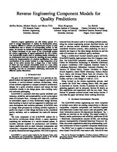
3.1 Scenario Diagram Metamodel Sequence diagrams [2] are among the crucial diagrams used during the analysis and design of object-oriented systems, as they are used to identify object responsibilities and 5
Our goal was to simplify our mapping rules and makes the implementation more efficient. 14
Carleton University, TR SCE-04-04
September 2004
interactions associated with each use case [5]. A sequence diagram describes how objects interact with each other through message sending, and how those messages are sent, possibly under certain conditions, in sequence. We have adapted the UML metamodel [21], that is, the class diagram that describes the structure of sequence diagrams, to our needs, so as to ease the generation of sequence diagrams from traces. Our sequence diagram metamodel is shown in Figure 1. Messages (abstract class Message) have a source and a target (role names sourceClassifier and destClassifier, respectively), both of type Classifier. The
source and destination objects of a message can be named objects (class Instance) or classes (class Class) in the cases where class scope methods are executed. A message can be an Operation call or the sending of a Signal. It can also correspond to the creation or destruction of an object (classes Create and Destroy) or the start of a thread. Messages can have arguments (class Argument) of different types (attribute type), i.e., primitive types, object types or even collection types. Depending on the type, the other attributes of Argument provide additional information: In the case of a primitive type, attributes value and type are self-explanatory; In the case of an instance of a user defined class, or a Java collection instance, type, value and nodeID are used to uniquely identify the instance in the instrumented distributed system. The attribute value captures the unique identification (for a given class) of the instance and nodeID uniquely represent nodes in the network, as further described in Section 4. Additionally, for Java collection instances, collInfo provides information on the contents of the collection, such as the list of its elements, i.e., values for primitive types or references for object types. Messages can be triggered under certain conditions called guard conditions (composition between Message and Condition). The {ordered} constraint on that composition corresponds to a logical conjunction of conditions that must be true for the message to be sent and those conditions are ordered in the code (e.g., nested if statements). Iterations of messages are modeled by class Repetition. Note that a Repetition is not a Message (no inheritance relationship between the two classes). A Repetition object specifies which messages are repeated (composition between Repetition and Message), the kind of repetition (e.g., for, while loop) and the condition under which the messages are 15
Carleton University, TR SCE-04-04
September 2004
repeated, i.e., the clause. Note that a Repetition object can have a guard condition, in the same way messages are guarded, and that the guard and the clause are different. This is to model the fact that a loop can itself be conditional. In the source code, for instance, this may correspond to the nested statements: if(A){while(B){…}}, where B is the clause of the repetition and A is its guard. Last, a message can trigger other messages: {ordered} self association on class Message. And the order of messages, possibly asynchronous and their possible grouping
in repetitions is devised using timestamps (in classes Message and Repetition) that allow us to order messages exchanged between objects in the distributed SUS. timestampSource and timestampDest in class Message refer to the sending and
receiving of the message, respectively, whereas class Repetition has only one timestamp corresponding to its start. Timestamps are further discussed in Section 4.1.
16
Carleton University, TR SCE-04-04
September 2004
Class Repetition
-name:String -classID:String -nodeID:int
Classifier
0..* OfClass 1..*
0..1 sourceClassifier
0..1 destClassifier
Instance -objectID:String
0..*
-kind:enum -forLoopVar:String -forLoopInc:String -timeStamp:int -nodeID:int
0..1
{ordered} 0..* messages guard 1..* {ordered} 0..*
0..*
clause
Condition
Message Signal
0..1
-signature:String -timestampSource:String -timestampDest:String
0..1
0..* -clause:String {ordered} guard
0..1 Create
1
0..* followingMessage {ordered}
0..*
arguments {ordered}
Argument Operation
Destroy
ThreadStart
-nodeID:int -value:String -type:String -CollInfo:String
-name:String
ReturnValue
Figure 1 – Scenario diagram metamodel (class diagram)
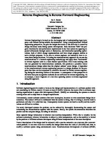
3.2 Trace Metamodel We instrument the SUS by processing the source code and the byte code and adding specific statements to the byte code, to retrieve the required information at runtime (Section 4). These statements are automatically added and produce text lines (referred to as trace statements) in the trace file, reporting on: -
Method entry and exit: The method signature, the class of the target object (i.e., the object executing the method), unique identifiers (in the distributed SUS) for the target object, and the arguments.
17
Carleton University, TR SCE-04-04
-
September 2004
Conditions: For each condition statement, the kind of the statement (e.g., “if”) and the condition as it appears in the source code are reported.
-
Loops: For each loop statement, the kind of the loop (e.g., “while”), the corresponding condition as it appears in the source code, and the end of the loop are reported.
-
Multithreaded and distributed information: Threads in which methods execute and RMI remote calls (in client) /executions (in server) are reported.
-
Use case information: It is important to specify the use cases that are executing. This can be done efficiently by either asking the user to identify operation(s) that start and end use cases or, even better, to use design sequence diagrams to identify these operations.
Note that in each case, a timestamp (based on each node’s local time) indicating when the event occurred is also reported in the trace (see discussion in Section 4.1 on why no global timestamps are necessary). From the trace files, it is possible to instantiate the class diagram in Figure 2, which is the metamodel for our traces. This class diagram is somewhat similar to our sequence diagram metamodel, though there are some important differences: For instance, a Message object has direct access to its source and target objects (instances of Classifier) in the scenario diagram metamodel (Figure 1) whereas a MethodExecution
has only access to the object that executes it, called the context (i.e., the target of the corresponding message) and has to query the method that called it (self association on MethodExecution with role name caller) to identify the source of the corresponding
message (Figure 2). This caller-callee information, though not directly available in the trace file (i.e., when reporting a method execution as a trace statement, the caller is not provided), can be determined off-line by analyzing the trace using the self association on ExecutionStatement. This association captures, for a given trace statement, the related
statement it is nested in (e.g., a method invocation statement directly nested in an “if” statement) or the statements that are directly nested into it (see example in Figure 3).
18
Carleton University, TR SCE-04-04
September 2004
Typically, given an instance of MethodExecution, say me, any instance of MethodExecution in collection me.nestedStatement is in collection me.callee.
Additionally, if instances of Repetition or IfStatement are in me.nestedStatement and have MethodExecution instances in their nestedStatement collection, these MethodExecution instances are also in me.callee. In other words, determining the
contents of me.callee amounts to recursively (transitive closure) detecting MethodExecution instances when navigating nestedStatement starting from me. A
similar association exists between classes Repetition and MethodExecution, with role name triggers: It represents all the calls (i.e, MethodExecution instances) that are triggered within a given Repetition instance. Again, this information is redundant since it can be retrieved with a recursive traversal of association nestedStatement. However, it has been added to the metamodel since, as we will see in Section 4, it will simplify the definition of consistency rules. Operation obtainConditions() has also been added for the sake of simplification: when several if-statements are nested, though the complete condition (the conjunction of the clauses) is not directly available, it can be computed using operation obtainConditions() in class ExecutionStatement that navigates nestedStatement:
The
post-condition
of
obtainConditions()
in
classes
MethodExecution, Repetition and IfStatement can be found in Table 3.
Table 3 – Post-conditions for obtainConditions() in classes MethodExecution, Repetition and IfStatement context MethodExecution::obtainConditions():Sequence(Clause) post: if (nestingStatement.oclIsTypeOf(IfStatement) then result = nestingStatement.obtainCondition() else result = null context Repetition::obtainConditions():Sequence(Clause) post: if (nestingStatement.oclIsTypeOf(IfStatement) then result = nestingStatement.obtainCondition() else result = null context IfStatement::obtainConditions():Sequence(Clause) post: if (nestingStatement.oclIsTypeOf(IfStatement) then result = nestingStatement.obtainCondition(). append(self.Clause) else result = self.Clause
19
Carleton University, TR SCE-04-04
September 2004 IfStatement
Clause 1
+obtainConditions:Sequenc
nestedStatement {ordered} 0..*
1 -clause:String clause 1
clause
ReturnValue
1
ExecutionStatement 0..1 -statement:String nestingStatement -timeStamp:String -threadID:int -nodeID:int
Repetition -kind:String -forLoopVar:String -forLoopInc:String
+obtainConditions:Sequenc
Argument
+obtainConditions:Sequenc 0..*
RemoteCall
0..* arguments {ordered}
-serverNodeID:in
-nodeID:int -type:String -value:String -collInfo:String
triggers 1..*
ThreadComm
MethodExecution
-kind:int
-name:String
1 endingMethod
0..1
1 startingMethod
0..1
+obtainConditions:Sequenc 1..* RemoteMethodExecuti -clientThreadID:int -clientNodeID:int -clientClassName:String -clientObjectID:int
0..* callee {ordered}
StartThreadCall
LocalExecution
-threadClassName:String -threadObjectID:int
-isCreate:boolean -isRun:boolean -isDestroy:boolean
caller 0..1
1
UseCaseExecutio -useCaseNum:int -useCaseInst:int -nodeID:int -timeStamp:String
context
Classifier
Class
Instance
-name:String -classID:int
-objectID:int 0..* 1 ofClass
Figure 2 – Trace metamodel (class diagram) Consider for example the code chunk for method mA(), in class A of Figure 3. This figure also shows an excerpt of the trace metamodel instance of an execution of mA() on an instance of class A, assuming condition c1 is true and the while loop is executed only once. An instance of LocalExecution is created for the execution of mA(): it has a context (i.e., an instance of class Instance) of class A. This LocalExecution instance has only one nestedStatement, i.e., an instance of class IfStatement (which clause is c1). The IfStatement instance has one nestedStatement, i.e., an instance of class Repetition (which clause is c2). An instance of LocalExecution is the only nestedStatement of the Repetition instance: the execution of method mB() on an
20
Carleton University, TR SCE-04-04
September 2004
instance of class B. From the nested nestedStatements links, a caller-callee link can be set between the two LocalExecution instances. context : LocalExecution caller
ofClass : Instance
name = "A"
nestedStatements clause : IfStatement
: Condition clause = "c1"
nestedStatements clause : Repetition
: Condition clause = "c2"
callee
: Class
name = "mA"
nestedStatements context : LocalExecution
public class A { … public void mA() { if (c1) { while (c2) { theB.mB(); } } } } ofClass
: Instance
name = "mB"
: Class name = "B"
Figure 3 – Instance example of the trace metamodel The trace metamodel includes information on method calls within the same thread, namely instances of LocalExecution, creation or destruction of objects (classes Create and Destroy). It also includes information on RMI remote calls: Class RemoteCall for the identification of the call on the client side and class RemoteMethodExecution for the identification of the actual execution on the server side. These classes’ context (inherited from MethodExecution) is defined as their caller and callee’s context, respectively. The main reason is that, in the context of RMI, their actual context would be a stub (client side) and a skeleton (server side) in the bytecode. We are, however, interested in the objects of the SUS source code, and not those introduced by the middleware during compilation and execution. Note that the scenario diagram metamodel does not include distribution information, which thus has to be abstracted into a Message instance when an instance of the trace metamodel is transformed into an instance of the scenario diagram metamodel (see Section 3.3). A call to method start() on a thread object triggers, through the virtual machine, the execution of a run() method. This is instrumented (see Section 4), and is therefore modeled in the trace metamodel with class StartThreadCall and Boolean attribute isRun of class LocalExecution. As for remote calls, class StartThreadCall’s context 21
Carleton University, TR SCE-04-04
September 2004
is its caller’s context as we are interested in which object triggers run(). Again, this information is abstracted in the trace metamodel into an asynchronous message between the two Contexts (or corresponding Classifiers). As for other possible asynchronous communications between threads, it is very difficult and sometimes even impossible to instrument the SUS to get the required information: we cannot predict, in general, when asynchronous communications occur and instrumenting threads method executions is not sufficient as they may not all be the result of asynchronous communications. Rather, since tasks communicate asynchronously through specific data structures, according to specific design strategies, we can gather information at runtime that can be used to abstract asynchronous messages when transforming an instance of the trace metamodel into an instance of the scenario metamodel. Indeed, it is considered good practice that specific design patterns be used to implement multithreaded systems [7, 10] (e.g., using a FIFO message queue) and that data exchanged asynchronously be modeled as instances of signal classes belonging to an inheritance hierarchy [2, 9]. Any signal is then an instance of a class that inherits from an abstract class often called Signal in a UML design. Data structures are then used by interacting threads to write and read information then manipulate signal objects. The strategy we adopted consists in instrumenting those data structures, resulting in specific MethodExecution instances, namely ThreadComm instances in the trace metamodel (see
Section 4). Using timestamps (see Section 4.1), it is then possible to know when signal objects are deposited and/or retrieved by which thread, thus resulting in asynchronous messages (see Section 3.3). As discussed above, the mapping between the two metamodels is not straightforward as the information required to create instances of the scenario diagram metamodel are often not readily available in trace statements (more than one statement is required) and the instance of the scenario diagram to be generated is an abstraction of the trace metamodel instance.
22
Carleton University, TR SCE-04-04
September 2004
3.3 Consistency rules We have derived five consistency rules, expressed in the OCL, that relate an instance of the trace metamodel to an instance of the scenario diagram metamodel. Note that these OCL rules only express constraints between the two metamodels. They are not algorithms, though they provide a specification and insights into how implementing such algorithms. In other words, those OCL expressions can be considered the postcondition of a single operation responsible for transforming an instance of the trace metamodel into an instance of the scenario metamodel. Note that Appendix A shows more complicated examples of scenario metamodel instances obtained from trace metamodel instances. Three consistency rules have been defined to match Message child classes from instances of MethodExecution child classes (Section 3.3.1), one consistency rule has been defined to identify links between Message instances, i.e., association followingMessage (Section 3.3.2), and one consistency rule has been defined to identify repetitions of Message instances (Section 3.3.3).
3.3.1 Identifying instances of Message child classes from instances of MethodExecution child classes
The
first
consistency
rule
describes
the
mapping
between
instances
of
Trace::MethodExecution child classes and instances of Scenario::Message child
classes (Figure 5). The most common situation occurs when two instances of LocalExecution are related by a caller-callee link (see Figure 2), as this corresponds
to an instance of Message child class Operation. The rule also handles all the other child classes of Trace::MethodExecution and Scenario::Message. The first six lines of the consistency rule in Figure 5 state that whenever two instances of Trace::MethodExecution, me1 and me2, satisfy either of four conditions, there exists a
corresponding instance of Scenario::Message. The four conditions are modeled as Boolean query operations to simplify and improve the readability of our OCL expressions: remoteCall(me1, me2), localCall(me1, me2), startThread(me1, me2) or threadComm(me1, me2). All four operations have two parameters of type MethodExecution, and their pre and post conditions can be found in Figure 6. In our tool 23
Carleton University, TR SCE-04-04
September 2004
prototype, they are implemented in utility class CheckMapping, which does not appear in our metamodel, but which will be referred to in OCL expressions making use of these operations. Operation localCall(me1, me2) then returns true when me1 and me2 are instances of LocalExecution and there is a caller-callee link between them (i.e., me1 calls me2),
which clearly results in a Message instance. Operation remoteCall(me1,me2) returns true when me1 and me2 are instances of RemoteCall and RemoteMethodExecution, respectively. Additionally, the attributes of me1 and me2 must match (values of threadID, nodeID, serverNodeID and context), that is me1 is a call on the RMI client side of a
remote method and corresponds on the server side to execution me2. This situation is further illustrated by a typical example trace metamodel instance in Figure 4 (a). Note that the instance of the trace metamodel created for the client (one trace file) is not linked in any way to the instance of the trace metamodel created for the server (another trace file). The purpose of the transformation of the trace metamodel instance into a scenario metamodel instance is to abstract this situation by transforming instances of RemoteCall and RemoteMethodExecution into a Message instance between the two related instances of LocalExecution.
(a) le1 : LocalExecution caller callee
: Class name = "classB" classID = 30
me1 : StartThreadCall threadObjectID = 20 threadClassName = "classB" threadCLassID = 30
ofClass : Instance
context
objectID = 20
me2 : LocalExecution isRun = true
(b)
(c)
Figure 4 – Examples of the first consistency rule
24
Carleton University, TR SCE-04-04
September 2004
Operation startThread(me1,me2) returns true when me1 is a StartThreadCall instance and me2 is an instance of LocalExecution whose attribute isRun is true (i.e., it is a run() execution). Furthermore, the attributes of me1 and me2 must match: attributes threadClassName, threadClassID and threadObjectID of me1 must match me2
attributes className, classID, and ObjectID, indicating that the call to start corresponding to me1 actually triggers the execution of method run() corresponding to me2. Figure 4 (b) illustrates the situation on an example: Note again that, though only one
trace file is involved here as the two threads execute on the same node in the network, the instance of the trace metamodel contains two separate parts. Operation threadComm(me1,me2) returns true when me1 writes a signal in a data structure and that signal is read by me2. As described and justified in Section 4, we assume asynchronous thread communications are performed by means of data structures that contain instances of Signal classes. In other words, these data structures are observed at runtime and operations that write or read Signal instances to and from them are caught, resulting in instances of class ThreadComm, of kind write or read, respectively. In order to abstract an asynchronous thread communication from MethodExecutions me1 and me2 (thus executing in two different threads), me1 and me2
must then be “write” and “read” ThreadComm instances with the same context (i.e., the data structure involved, as modeled by an association in the trace metamodel). Furthermore, me1 unique signal argument, i.e., the signal sent by the thread executing me1, must be the signal returned by me2. Again, a typical situation is illustrated in Figure
4 (c). Note that the argument and the returned value are two different instances. However, the OCL equality between instances is a logical equality, i.e., the objectID attribute of the two instances must have identical values to correspond to the same signal. Note that several ThreadComm instances of kind read can be associated with a single ThreadComm instance of kind write, as long as they all manipulate the same Signal instance in the same data structure. This corresponds to an asynchronous message sent to more than one thread. The rest of the consistency rule in Figure 5 ensures that the attributes of me1 and me2, as identified by either of the four query operations, and the matching Message instance mes 25
Carleton University, TR SCE-04-04
September 2004
are consistent. First, timestamps of me1, me2 and mes are checked: mes.timestampDest equals to me2.timestamp and mes.timestampSource equals to me1.timestamp, except in the case of a local call, where both timestamps of mes are equal to me2.timestamp. Next, contexts of me1 and me2 correspond to source and target classifiers of mes, respectively.
(This is checked using operation mapContextClassifier() which postcondition is provided in Figure 7.) However, in the case where me1 and me2 are instances of threadComm, me1 and me2’s callers’s context are used to map to the source and target
classifiers of mes. The rule also ensures that the arguments of mes match the ones of me2 (using operation mapExecutionMessageArgs() which post condition is provided in Figure 7). The mapping between me1 or me2 conditions (using operation obtainConditions())
and
mes
guard
condition
is
then
verified.
In
case
localCall(me1,me2) is true, mes guard is me2.obtainConditions(). However, in all
the other three situations, the guard is me1.obtainCondition(), since the conditions that lead to the sending of mes are linked with me1 in the trace metamodel instance. For instance, if an asynchronous message is sent between two threads, an instance of ThreadComm (kind=#write) appears in the trace metamodel instance and is associated
with a Condition instance. It is this condition that decides of the sending of the message. Last, the signature, name and actual type (child class of Message) of the message are checked. For instance, when localCall(me1,me2) is true, if me2 is a constructor or a destructor, so is mes (instance of Create or Destroy) otherwise mes is an instance of Operation.
Last, note that two other consistency rules are necessary in this section to map Message instances to MethodExecution instances that cannot be paired with any other MethodExecution instance to satisfy any of the four query operations we used. Indeed,
there may exist LocalExecution instances in the trace metamodel instance without any caller. This is the case of method main(): it is not called by any other method. Other
typical examples are calls that originate from non instrumented subsystems (e.g., a GUI subsystem).
These
LocalExecution
instances
are
nevertheless
mapped
to
Scenario::Operation instances, though the message does not have a source classifier.
Similarly, a trace metamodel instance may not contain any LocalExecution instance with attribute isRun equal to true corresponding to a given StartThreadCall instance. 26
Carleton University, TR SCE-04-04
September 2004
Another similar case is when the sender or receiver of a signal is detected, but not both. The corresponding mappings for the above special cases are the purpose of consistency rules in Figure 8 and Figure 9. Trace::MethodExecution.allInstances->forAll( me1: Trace::MethodExecution, me2: Trace::MethodExecution | CheckMapping.localCall(me1,me2) or CheckMapping.remoteCall(me1,me2) or CheckMapping.startThread(me1, me2) or CheckMapping.threadComm(me1, me2) implies Scenario::Message.allInstances->exists(mes: Scenario::Message | //timestamps if CheckMapping.localCall(me1, me2) then ( mes.timestampSource = me2.timestamp and mes.timestampDest = me2.timestamp ) else ( mes.timestampSource = me1.timestamp and mes.timestampDest = me2.timestamp ) endif and if CheckMapping.threadComm(me1, me2) then ( //the context of me1’s caller is the source of message mes CheckMapping.mapContextClassifier(me1.caller.context, mes.sourceClassifier) and //the context of me2’s caller is the target of message mes CheckMapping.mapContextClassifier(me2.caller.context, mes.destClassifier) ) else ( //the context of me1 is the source of message mes and CheckMapping.mapContextClassifier(me1.context, mes.sourceClassifier) //the context of me2 is the target of message mes and CheckMapping.mapContextClassifier(me2.context, mes.destClassifier) ) //compare arguments (matching entire sequences) and CheckMapping.mapExecutionMessageArgs(me2, mes) and //mapping the message guard to me1 or me2 conditions if CheckMapping.localCall(me1,me2) then ( mes.guard.clause = me2.obtainConditions() ) else ( mes.guard.clause = me1.obtainConditions() ) endif //mapping the exact message type, along with message name and signature and CheckMapping.localCall(me1,me2) implies ( mes.signature = me2.statement and mes.name = me2.name and me2.isCreate = true implies mes.oclType = Scenario::Create and me2.isDestroy = true implies mes.oclType = Scenario::Destroy and not (me2.isCreate = true or me2.isDestroy = true) implies mes.oclType = Scenario::Operation ) and CheckMapping.remoteCall(me1,me2) implies ( mes.signature = me2.statement and mes.name = me2.name and mes.oclType = Scenario::Operation ) and CheckMapping.startThread(me1, me2) implies ( mes.oclType = ThreadStart and mes.signature = me2.statement ) and CheckMapping.threadComm(me1, me2) implies ( mes.oclType = Signal ) ) // Scenario::Message.allInstances->exists )
Figure 5 – Mapping Trace::MethodExecution instances to Scenario::Message instances
27
Carleton University, TR SCE-04-04
September 2004
context CheckMapping::localCall( le1: MethodExecution, le2: MethodExecution ): Boolean post: result = le1.oclType = LocalExecution and le2.oclType = LocalExecution and le1.callee->includes(le2) context CheckMapping::remoteCall( rc: MethodExecution, rme: MethodExecution ): Boolean post: result = rc.oclType = RemoteCall and rme.oclType = RemoteMethodExecution and rc.serverNodeID = rme.nodeID and rc.threadID = rme.clientThreadID and rc.nodeID = rme.clientNodeID and if rc.context.oclType = Trace::Instance then ( rc.context.objectID = rme.clientObjectID and rc.context.ofClass.classID = rme.clientClassID } else (rc.context.classID = rme.clientClassID ) endif context CheckMapping::startThread( stc: MethodExecution, le: MethodExecution ): Boolean post: result = stc.oclType = StartThreadCall and le.oclType = LocalExecution and le.isRun = true and stc.threadClassName = le.context.ofClass.name and stc.threadClassID = le.context.ofClass.classID and stc.threadObjectID = le.context.objectID and stc.nodeID = le.nodeID context CheckMapping::threadComm( tc1: MethodExecution, tc2: MethodExecution ): Boolean post: result = tc1.oclType = ThreadComm and tc1.kind = #write and tc2.oclType = ThreadComm and tc2.kind = #read and tc1.arguments->at(1) = tc2.returnValue and tc1.context = tc2.context
Figure 6 – Postconditions for operations localCall(), remoteCall(), startThread() and threadComm() in class CheckMapping context CheckMapping::mapContextClassifier( co : Trace::Classifier, cl : Scenario::Classifier): Boolean post: result = if (co.oclType = Trace::Instance) then ( cl.oclType = Scenario::Instance and cl.objectID = co.objectID and cl.ofClass.name = co.ofClass.name and cl.ofClass.classID = co.ofClass.classID and cl.ofClass.nodeID = co.ofClass.nodeID ) else ( cl.oclType = Scenario::Class and cl.name = co.name and cl.classID = co.classID and cl.nodeID = co.nodeID ) endif Context CheckMapping::mapExecutionMessageArgs( me : Trace::MethodExecution, m : Scenario::Message): Boolean post: result = m.arguments.nodeID = me.arguments.nodeID and m.arguments.value = me.arguments.value and m.arguments.type = me.arguments.type and m.arguments.collInfo = me.arguments.collInfo and Sequence{1..me.arguments->size}->forAll(index: Integer | if me.arguments->at(index).oclType = Trace::ReturnValue then m.arguments->at(index).oclType = Scenario::ReturnValue else m.arguments->at(index).oclType = Scenario::Argument endif )
Figure 7 – Post condition of operation CheckMapping::mapContextClassifier() and CheckMapping::mapExecutionMessageArgs()
28
Carleton University, TR SCE-04-04
September 2004
Trace::MethodExecution.allInstances->forAll( me2: Trace::MethodExecution | MethodExecution.allInstances->select(me1: Trace::MethodExecution | CheckMapping.localCall(me1,me2) or CheckMapping.startThread(me1, me2) or CheckMapping.threadComm(me1, me2) )->Empty implies //me2 does not have a caller => message without source Scenario::Message.allInstances->exists(mes: Scenario::Message | //timestamps if CheckMapping.localCall(me1, me2) then ( mes.timestampSource = me2.timestamp and mes.timestampDest = me2.timestamp ) else ( mes.timestampSource = me1.timestamp and mes.timestampDest = me2.timestamp ) endif //there is no source and mes.sourceClassifier = null //the context of me2 is the target of message mes and CheckMapping.mapContextClassifier(me2.context, mes.destClassifier) //compare arguments (matching entire sequences) and CheckMapping.mapExecutionMessageArgs(me2, mes) //we do not have the caller, thus no access to the conditions/guard and mes.guard = null //mapping the exact message type, along with message name and signature and me2.oclType = LocalExecution and me2.isRun = false implies ( mes.signature = me2.statement and mes.name = me2.name and me2.isCreate = true implies mes.oclType = Scenario::Create and me2.isDestroy = true implies mes.oclType = Scenario::Destroy and not (me2.isCreate = true or me2.isDestroy = true) implies mes.oclType = Scenario::Operation ) and me2.oclType = LocalExecution and me2.isRun = true implies ( mes.oclType = ThreadStart and mes.signature = me2.statement ) and me2.oclType = ThreadComm implies ( mes.oclType = Signal } ) // Scenario::Message.allInstances->exists )
Figure 8 – Incomplete mapping of Trace::MethodExecution instances to 6
Scenario::Message instances
6
Note that because of our instrumentation strategy, not having a RemoteCall instance (the caller) for a given RemoteMethodExecution is not possible. Similarly, not having a RemoteMethodExecution instance for a given RemoteCall instance is not possible. 29
Carleton University, TR SCE-04-04
September 2004
Trace::MethodExecution.allInstances->forAll( me2: Trace::MethodExecution | MethodExecution.allInstances->select(me1: Trace::MethodExecution | CheckMapping.startThread(me2, me1) or CheckMapping.threadComm(me2, me1) )->isEmpty implies //me2 does not have a callee => message without destination Scenario::Message.allInstances->exists(mes: Scenario::Message | //timestamps mes.timestampSource = me2.timestamp and mes.timestampDest = me2.timestamp //the context of me2 is the source of message mes and CheckMapping.mapContextClassifier(me2.context, mes.sourceClassifier) //there is no target and mes.destClassifier = null //compare arguments (matching entire sequences) and CheckMapping.mapExecutionMessageArgs(me2, mes) //mapping the message guard to me1 or me2 conditions mes.guard.clause = me1.obtainConditions() //mapping the exact message type, along with message name and signature and me2.oclType = LocalExecution and me2.isRun = true implies ( mes.oclType = ThreadStart and mes.signature = me2.statement and mes.name = me2.name ) and me2.oclType = ThreadComm implies ( mes.oclType = Signal and mes.name = me2.arguments->at(1).name } ) // Scenario::Message.allInstances->exists )
Figure 9 – Incomplete mapping of Trace::MethodExecution instances to Scenario::Message instances
6,7
3.3.2 Identifying followingMessage links The identification of the following messages of a given message (association followingMessage in the scenario metamodel in Figure 1), is the purpose of a separate
rule. It requires that all the messages be identified, using the rules described in the previous section. Recall that self association followingMessage on Scenario::Message specifies the ordered sequence of messages that are triggered by a given message. This is the purpose of the consistency rule shown in Figure 10. It is the conjunction of two OCL expressions. The first one identifies, for a given Message instance m1, the set of Message instances that are triggered by m1 among the set of all the Message instances
which have m1 destination classifier as source classifier. This is performed using timestamps of Message instances (timestampDest and timestampSource). Message instance
m2
is
triggered
by m1 if
and
only
if
m1
destination
classifier
(m1.destClassifier) is m2 source classifier (m2.sourceClassifier), m2 is sent after
7
Note that LocalCall() is not involved in this rule. Indeed, it is perfectly legal for a LocalExecution instance to have no callee. 30
Carleton University, TR SCE-04-04
September 2004
m1 is received (m1.timestampDest < m2.timestampSource) and there is no other Message instance sent to that classifier between those two timestamps.
The second conjunction checks that the elements of Sequence m.followingMessage, for
any
Message
instance
m,
are
sorted
according
to
their
timestamps
(timestampSource). Scenario::Message.allInstances->forAll( m1: Message, m2: Message | m1.destClassifier = m2.sourceClassifier ( and m1.timestampDest < m2.timestampSource and Scenario::Message.allInstance->select( m: Message | m.destClassifier = m1.destClassifier and m.timestampDest > m1.timestampDest and m.timestampDest < m2.timestampSource )->isEmpty ) implies m1.followingMessage->includes(m2) ) and Scenario::Message.allInstances->forAll(m: Message | Sequence{1..m.followingMessage->size}->forAll(i: Integer, j: Integer | i > j implies m.followingMessage->at(i).timestampSource > m.followingMessage->at(j).timestampSource )
Figure 10 – Identifying followingMessage links between Message instances 3.3.3 Identifying repetitions of Message instances The last consistency rule matches instances of class Trace::Repetition and instances of class Scenario::Repetition (Figure 11). In its first three lines, the rule states that any
instance
of
Scenario::Repetition
corresponds
to
an
instance
of
Trace::Repetition that is associated with MethodExecution instances. Indeed, a Scenario::Repetition instance is associated with Message instances, and the Trace::Repetition instance must thus involve the MethodExecution instances that
correspond to these Messages. The rest of the rule describes how the Trace::Repetition and Scenario::Repetition instances relate to each other, that is, how their attributes and links relate to each other. First, the kind of repetition, the clause, and the possible guard condition under which the repetition occurs must match (recall the distinction between the two associations relating classes Scenario::Repetition and Scenario::Condition).
31
Carleton University, TR SCE-04-04
September 2004
Trace::Repetition.allInstances->forAll(Trep: Trace::Repetition | Trep.triggers->notEmpty implies Scenario::Repetition.allInstances->exists(Srep: Scenario::Repetition | //compare attributes Srep.kind = Trep.kind and Srep.forLoopVar = Trep.forLoopVar and Srep.forLoopInc = Trep.forLoopInc and Srep.timeStamp = Trep.timeStamp and Srep.clause.clause = Trep.clause.clause //compare clause //compare conditions (compare whole sequences) and Trep.getConditions().clause = Srep.guard.clause //compare Messages/MethodExecutions in repetitions and Trep.triggers->forAll(me: MethodExecution | Srep->includesAll(CheckMapping.getMessages(me)) ) ) )
Figure 11 – Mapping Trace::Repetition to Scenario::Repetition Last, the Message instances associated with the Scenario::Repetition instance must match the MethodExecution instances associated with the Trace:Repetition instance. This is checked using query operation getMessage(me:MethodExecution), which postcondition can be found in Figure 12. The following four different cases have to be considered: -
MethodExecution
instance
me,
in
the
Trace::Repetition,
is
a
LocalExecution. In this case, getMessage(me) returns the (unique) Message
instance that corresponds to me. It uses me’s context and timestamp to check the message destClassifier and timestampDest and me caller’s context and timestamp to check the message sourceClassifier.
-
8
MethodExecution instance me is a RemoteCall . In this case, getMessage(me)
returns the (unique) Message instance that corresponds to me, using me’s context and timestamp and the context and timestamp of the RemoteMethodExecution corresponding to me (using operation getRemoteMethodExecution() in Figure 13).
8
Note that RemoteMethodExecution instances cannot be triggered by Repetition instances since they are artificially introduced by our instrumentation procedure (i.e., wrappers), i.e., they do not correspond to executions of methods in the SUS. 32
Carleton University, TR SCE-04-04
-
MethodExecution
September 2004
instance me is a StartThreadCall9. In this case,
getMessage(me) returns the (unique) Message instance that corresponds to me,
using me’s context and timestamp and the context and timestasmp of the LocalExecution instance (with attribute isRun equal to true) corresponding to me (using operation getRunExecution() in Figure 13).
-
MethodExecution instance me is a ThreadComm. In this case, getMessage(me)
returns Message instances in which me is involved (using operation getThreadComm() in Figure 13). More than one Message instance can be
returned, as discussed previously in Section 3.3.1. CheckMapping::getMessages(me:MethodExecution):Sequence(Message) post: me.oclType = LocalExecution implies result = Message.allInstances->select(m:Message | mapContextClassifier(me.context, m.destClassifier) and mapContextClassifier(me.caller.context, m.sourceClassifier) and m.timestampDest = me.timestamp and m.timestampSource = me.timestamp )->asSequence and me.oclType = RemoteCall implies result = Message.allInstances->select(m:Message| mapContextClassifier( getRemoteMethodExecution(me).context, m.destClassifier) and mapContextClassifier(me.context, m.sourceClassifier) and m.timestampDest = getRemoteMethodExecution(me).timestamp and m.timestampSource = me.timestamp )->asSequence and me.oclType = StartThreadCall implies result = Message.allInstances->select(m:Message| mapContextClassifier(getRunExecution(me).context, m.destClassifier) and mapContextClassifier(me.context, m.sourceClassifier) and m.timestampDest = getRunExecution(me).timestamp and m.timestampSource = me.timestamp )->asSequence and (me.oclType = ThreadComm and me.kind=#write) implies result = Message.allInstances->select(m:Message| getThreadCommRemove->forAll(tcr:ThreadCommRemove| mapContextClassifier(tcr.context, m.destClassifier) and m.timestampDest = tcr.timestamp ) and mapContextClassifier(me.context, m.sourceClassifier) and m.timestampSource = me.timestamp )->asSequence
Figure 12 – Postcondition of operation CheckMapping::getMessages()
9
Note that LocalExecution instances with attribute isRun equal to true cannot be triggered by Repetition instances since the run() method of threads is automatically executed by the Java Virtual Machine (not the SUS source code). 33
Carleton University, TR SCE-04-04
September 2004
CheckMapping::getRemoteMethodExecution(rc:RemoteCall):RemoteMethodExecution post: result = RemoteMethodExecution.allInstances->select( rme | rme.clientThreadID = rc.threadID and rme.nodeID = rc.serverNodeID and rme.clientNodeID = rc.nodeID and if rc.context.oclType = Trace::Instance then ( rc.context.objectID = rme.clientObjectID and rc.context.ofClass = rme.clientClassID ) else ( rc.context.classID = rme.clientClassID ) endif )->asSequence->at(1) CheckMapping::getRunExecution(stc:StartThreadCall):LocalExecution post: result = LocalExecution.allInstances->select(le:LocalExecution| le.isRun = true and stc.threadClassName = le.context.ofClass.name and stc.threadClassID = le.context.ofClass.classID and stc.threadObjectID = le.context.objectID )->asSequence->at(1) CheckMapping::getThreadComm(tc:ThreadComm):Set(ThreadComm) post: tc.kind = #write implies result = ThreadComm.allInstances->select(p:ThreadComm| p.kind = #read and p.context = tc.context and p.returnValue = tc.argument->at(1) )
Figure 13 – Postconditions of operations getRemoteMethodExecution(), getRunExecution() and getThreadComm() of class CheckMapping
4 INSTRUMENTATION As discussed in Section 1, in order to alleviate the issues usually associated with instrumenting source code (e.g., two different versions of the source code to maintain), we aim at using a less intrusive instrumentation strategy. To that effect we aim at instrumenting the Java bytecode instead of the Java source code. The immediate advantages are that only one version of the source code is to be maintained when changes to the source code are made, and that the source code is not polluted with instrumentation statements. In this work, we thus use Aspect-Oriented Programming (AOP) [8] to support the instrumentation of Java systems’ bytecode, and more specifically AspectJ [12], as we aim at reverse-engineering Java software. AspectJ allows us to intercept certain behavior in the Java SUS (e.g., the execution of a method) and add specific behavior towards our reverse-engineering goal accordingly (e.g., a println() statement reporting the execution of an intercepted method execution).
34
Carleton University, TR SCE-04-04
September 2004
Section 4.1 discusses the issue of local versus global clocks and justifies why local clocks are sufficient in this work, since we assume RMI is the middleware used in the SUS (the impact of this assumption is discussed in Section 6). Section 4.2 briefly introduces AOP and AspectJ. Section 4.3 then illustrates our use of AspectJ to instrument three specific constructs relevant to our problem: Method executions, and RMI and Thread communications. Other usages of AspectJ can be found in Appendix B. Note that, unfortunately, AspectJ does not currently provide any mechanism to intercept control-flow statements executions, which is a requirement if we are to produce accurate sequence diagrams (recall that both our trace and scenario diagram metamodels include information on conditions and repetitions). However, this has been identified as a possible addition to future releases of AspectJ10. Thus, as a temporary solution (waiting for this future release), we also instrument the Java source code to intercept control-flow statements executions (Section 4.4). This can only be temporary though as it defeats our important objective of not instrumenting the source code at all. That instrumentation was however designed to be lightweight and does not affect much the source code, as described in Section 4.4, in terms of its comprehensibility and size.
4.1 Local clocks vs. global clock This section describes our strategy to identify the order of execution of methods in a distributed SUS (trace metamodel) and, as a consequence, the order of the messages exchanged by the objects composing the SUS (scenario metamodel). More specifically we explain below how we do that by just using local clocks for each node in the SUS rather than a global clock for the whole SUS [13, 23]. First, the order of executions occurring on each node, whether in one or several threads of executions, can be captured by each node local clock. In other words, for a given ExecutionStatement instance es, the elements of collection es.nestedStatements can
be ordered according to their timestamps, which are all larger than es’s timestamp. Using only timestamps from local clocks is not sufficient when we want to identify a
10
This has been discussed on mailing lists by the developers of AspectJ 35
Carleton University, TR SCE-04-04
September 2004
causality relationship between executions occurring at different nodes in the network since local clocks may not be synchronized: For instance, assuming RemoteCall instance rc triggers (through RMI) RemoteMethodExecution rme, rme’s timestamp may be
smaller than rc’s timestamp, though rc execution predates rme’s. In order to alleviate this problem, we have added information to RemoteCall and RemoteMethodExecution classes, and our instrumentation strategy ensures this
information is retrieved and is part of the trace statements. In addition to the timestamp, threadID and nodeID inherited from ExecutionStatement, class RemoteCall holds the
node identifier of the server node (serverNodeID), and class RemoteMethodExecution holds the client’s node identifier (clientNodeID), thread identifier (clientThreadID), class name (clientClassName) and object identifier (clientObjectID). Let us describe how, using this information, it is then possible to identify whether a given RemoteCall instance rc triggers a specific RemoteMethodExecution instance rme. First,
their
node
identifiers
must
match,
i.e.,
rme.nodeID=rc.serverNodeID
and
11
rme.clientNodeID=rc.nodeID . This is not sufficient since, for instance several
threads in the client may perform RMI calls to the same server. As a consequence, a necessary condition for deciding that rme is triggered by rc is that rme.clientThreadID = rc.clientThreadID. Again, this is not sufficient since several remote calls may be
performed in the client thread. However, RMI calls are synchronous, that is when a thread at the client side performs a call to a remote method, it blocks until the remote execution terminates. As a consequence, the order of calls to remote methods (at the client side) corresponds to the order of remote method executions (at the server side). So, to decide that rme is triggered by rc one simply checks if (1) rc is the ith call to a remote method and (2) rme is the ith remote method execution. Remote calls performed by the client are ordered according to their timestamps (using the local clock of the client), remote method executions are ordered according to their timestamps (using the local
11
Without attribute serverNodeID in class RemoteCall we would not be able to distinguish two remote calls (to the same remote method) performed by the same client on two different servers. Without attribute clientNodeID in class RemoteMethodExecution, we would not be able to distinguish two remote method executions (of the same method) performed by two different clients. 36
Carleton University, TR SCE-04-04
September 2004
clock of the server), and what really matters here is the order (we do not compare timestamps of remote calls and remote executions). To summarize, we order method executions and find a causality relationships between them as follows: -
In case of two executions in the same thread (at the same node in the SUS), timestamps retrieved from the local clock are sufficient.
-
In case of remote communications between a thread (threadID T) at client node (nodeID X) and a server (nodeID Y), we do the following: (1) we order the remote calls to Y within T (attribute serverNodeID=Y); (2) we order the remote method execution performed on Y and triggered by T on X (clientNodeID=X and clientThreadID=T); (3) We match elements in these two sequences according to
their position. This methodology applies only in the ideal case where remote method calls are successful and no messages are lost. A solution to this would be to send the caller’s timestamp along with its thread and node identifiers. However, this is not implemented in the present work. Note
that
attributes
clientObjectID
and
clientClassID
in
class
RemoteMethodExecution have not been mentioned. They are only used to limit the
search for matching between RemoteCall and RemoteMethodExecution instances, i.e., to limit the size of RemoteCall and RemoteMethodExecution collections to be ordered.
4.2 Aspect Oriented Programming and AspectJ Aspect-oriented programming [8] is a recent methodology that facilitates the modularization of concerns in software development. In particular, it extracts scattered concerns from classes and turns them into first-class elements: aspects. By decoupling these concerns and placing them in aspects, the original classes are relieved of the burden of managing functionalities orthogonally related to their purpose. Later, the aspect code is injected into appropriate places by a process known as weaving. Aspects contain join 37
Carleton University, TR SCE-04-04
September 2004
points that specify well-defined execution “points” in the execution of the instrumented program where aspect code interacts, e.g., a specific method call or execution. Pointcuts describe sets of join points by specifying, for example, the objects and methods to be considered. An advice is additional code that should execute before or after join points. It can even have control on whether the join point can run at all. A direct consequence of aspect use is that less code needs to be written, code that would otherwise be spread throughout the system can now be localized in one place. By keeping aspects separate from the SUS methods they interact with, the SUS source code is more maintainable and easier to understand. This work uses AspectJ (AOP for Java), a well-known implementation of AOP. The general structure of an AspectJ aspect can be found in Figure 14. The first line of the aspect, following the AspectJ syntax [12], specifies its signature, which starts with one of the three possible types of advice, namely before (used to execute some code right before the point cut), after (used to execute some code right after the point cut), and around (used to execute some code before and after the pointcut): Figure 14 specifies an around advice. The pointcut declaration follows the advice type. Different functionalities are available to specify the pointcut. It is for instance possible, using the execution and within functionalities, to specify a pointcut as any execution of specific method name,
say getName(), in any class in any package, except in a given package, say somePackage, as in Figure 14. Other such functionalities can be found in [12]. Following
the pointcut declaration is the advice proper, that is, what has to be done before, after or around the execution of the pointcut. In the around case, one can decide to execute the original point cut using AspectJ statement proceed(), as in Figure 14, and execute whatever Java statements are deemed necessary before and after (in case of an around advice) this execution. One can even decide not to execute the original pointcut. The reader interested in more technical details on AspectJ is referred to [12]. around(): execution(* * *.getName()) && !within(* * somePackage) { // any Java statement proceed(); // any Java statement }
Figure 14 – General structure of an AspectJ aspect, an example
38
Carleton University, TR SCE-04-04
September 2004
4.3 Usage of AspectJ First, AspectJ is used to add attributes, methods, and interfaces to classes in the SUS so that, during SUS methods executions, unique identifiers required by the trace metamodel (Figure 2) are correctly set and available to other aspects: SUS nodes have unique identifiers (attribute nodeID in class ExecutionStatement); SUS class instances are uniquely identified by an object identifier (attribute objectID in class Instance) and their class name, and also implement the ObjectID interface; Executing threads are uniquely identified (attribute threadID in class ExecutionStatement). We illustrate below our use of AspectJ by means of three examples: Intercepting constructor and (static) method executions (Section 4.3.1); Intercepting RMI communications (Section 4.3.2); Intercepting thread communications (Section 4.3.3). A complete list of aspect templates, including templates related to the interception of control flow structures, can be found in Appendix B. Each time, instead of an aspect, which would be specific to a particular SUS, we show aspect code templates that are required to instrument the bytecode. These templates are generic descriptions of aspects showing what parts vary according to the SUS: The varying parts will be written in bold face. Aspects use utility classes that are provided in an instrumentation package where the aspects are also located. 4.3.1 Intercepting Constructor and Method Executions In order to instantiate class LocalExecution in the trace metamodel (Figure 2), it is important to intercept any execution of any method in the SUS. Since the information we have to manipulate (i.e., retrieve from the SUS execution and use to instantiate the trace metamodel) is different for a constructor12, a static method and a non-static method, we devise three aspect templates discussed in this section. The first template (Figure 15) is for tracing constructor executions. It specifies an around advice as we want to produce trace information before and after the execution of the 12
Note that, since there is no real destructor in Java, we do not have any aspect for that construct. 39
Carleton University, TR SCE-04-04
September 2004
constructors. Indeed, we want to detect when (i.e., at which moments in time) constructors start and end executing as this will tell us what are their nested statements (Figure 2): the statements within the same thread (uniquely identified by the threadID) between the two timestamps reported at constructor start and end. The point cut specified in Figure 15 is any execution of method new (AspectJ notation to indicate constructors) with any number of parameters (new(..)), on any class in a given package13 that is the SUS (AspectJ key word within). Note that any around advice must return an instance of type Object (Object around():…) though it is not useful for constructors so that we only return null. The point cut also prevents any tracing of the aspects themselves, assuming aspect class names are in a specific package, namely Instrumentation (!within(Instrumentation.*)).
Before the execution of the constructor the advice reports on: -
The type of pointcut (e.g., the execution start of a constructor labeled as “Create method start”);
-
The name of the class for which an instance is to be created;
-
The signature of the constructor, which is obtained by using AspectJ’s reflection facilities.
The thread identifier, node identifier and timestamp are taken care by the instrument(List, Object[]) method, so these are not included in the list of strings.
The execution of the (intercepted) constructor is achieved using AspectJ statement proceed(). After the execution of the constructor, but before the end of the advice, the
advice reports on: the end of the constructor execution (“Create method end”) and the unique object identifier of the newly created object. Note that in order to get the objectID,
the reference of the created object (obtained in AspectJ with
thisJoinPoint.getThis()) is casted to ObjectID (see section B.2).
13
Specifying
multiple
packages
or
classes
can
be
performed
as
follows:
( execution(PackageName1..* new(..)) || execution(PackageName2..* new(..)) || execution(PackageName3.className new(..)) ) && !within(Instrumentation.*).
40
Carleton University, TR SCE-04-04
September 2004
As a result, given a trace statement reporting on the execution of class A’s constructor at timestamp t1 and a trace statement reporting on the end of this constructor at timestamp t2, any trace statement with the same thread identifier as the two above statements with a timestamp between t1 and t2 is executed by the constructor. This is how nested statements are identified and ordered in the trace metamodel (Figure 2). Object around(): execution(PackageName..*.new(..)) && !within(Instrumentation.*) { ArrayList log = new ArrayList(); log.add("Create method start"); log.add(thisJoinPointStaticPart.getSourceLocation().getWithinType().getName()) ; log.add(thisJoinPointStaticPart.getSignature().toLongString()); LoggingClient.getLoggingClient().instrument(log, thisJoinPoint.getArgs()); proceed(); log.clear(); log.add("Create method end"); log.add(String.valueOf(((ObjectID) thisJoinPoint.getThis()).getObjectID())); LoggingClient.getLoggingClient().instrument(log, null); return null; }
Figure 15 – Aspect template for tracing constructor executions The next two templates are very similar to the first one. The template in Figure 16 is for tracing any static method executions (thus the keyword static in the pointcut declaration). The main difference is that after the execution of the static method, no object identifier is reported, but information on the possible returned value is (the second parameter to the instrument(List, Object[]) method).
The template in Figure 17 is for tracing non-static method executions that are not run() methods in threads: intercepting executions of run() methods in threads is the focus of Section 4.3.3. What is new in the pointcut declaration are references to self. This allows the advice to use keyword self as a reference to the object on which the intercepted method is executed and prevents this pointcut from catching static methods (this(self) is null). Consequently, the advice reports on the self object unique identifier before the intercepted method execution.
41
Carleton University, TR SCE-04-04
September 2004
Object around(): execution(static * PackageName..*.*(..)) && !within(Instrumentation.*) { ArrayList log = new ArrayList(); log.add("Static method start"); log.add(thisJoinPointStaticPart.getSourceLocation().getWithinType().getName()) ; log.add(thisJoinPointStaticPart.getSignature().toLongString()); log.add(thisJoinPointStaticPart.getSignature().getName()); LoggingClient.getLoggingClient().instrument(log, thisJoinPoint.getArgs()); Object[] returnArg = {proceed()}; log.clear(); log.add("Static method end"); LoggingClient.getLoggingClient().instrument(log, returnArg); return returnArg[0]; }
Figure 16 – Aspect template for tracing static method executions Object around(Object self): execution(* PackageName..*.*(..)) && !within(Instrumentation.*) && !execution(void Runnable+.run(..)) && this(self) { ArrayList log = new ArrayList(); log.add("Method start"); log.add(String.valueOf(((ObjectID) self).getObjectID())); log.add(self.getClass().getName()); log.add(thisJoinPointStaticPart.getSignature().toLongString()); log.add(thisJoinPointStaticPart.getSignature().getName()); LoggingClient.getLoggingClient().instrument(log, thisJoinPoint.getArgs()); Object[] returnArg = {proceed(self)}; log.clear(); log.add("Method end"); LoggingClient.getLoggingClient().instrument(log, returnArg); return returnArg[0]; }
Figure 17 – Aspect template for tracing non-static method executions 4.3.2 Intercepting RMI Communications Using RMI in Java, a call to a remote method (i.e., a call to an object whose class implements java.rmi.Remote), is very similar to a call to a local object. For instance, RMI provides synchronous communication, i.e., when the RMI client invokes a remote method at the server, the client itself is blocked until the method invoked returns. In addition, the remote method executing at the server does not have any information on the client it is serving. As a consequence, since the call and the execution occur on two different nodes in the network, we cannot rely on the conjunction of node identifiers, thread identifiers and timestamps to order trace information. We thus have to intercept 42
Carleton University, TR SCE-04-04
September 2004
executions of methods in classes implementing interface java.rmi.Remote on the server side, and calls to methods on objects which class implements interface java.rmi.Remote on the client side. Server side Additionally, we have to gather enough information when intercepting these calls/executions to match a call on the client side with an execution on the server side: We will see below that information thus has to be passed and returned along with the call. In order to do so we create aspects that wrap around methods in java.rmi.Remote interfaces on the server side. For each such remote method, named for instance myRemoteMethod(…), the aspect adds method myRemoteMethodExtra(…) (with its body)
to the interface14. This added method has one additional parameter that is used to pass information about the client performing the call: i.e., client threadID, nodeID, className, objectID (recall class RemoteMethodExecution in the trace metamodel). It
also has a different returned value to pass information on the server back to the client: the serverNodeID (Figure 2). The added parameter containing client information is used by myRemoteMethodExtra(…)
to
produce
the
trace
on
the
server
side,
and
myRemoteMethodExtra(…) then calls the original method myRemoteMethod(…) with the
original arguments. This will result into a caller-callee relationship between an instance of RemoteMethodExecution (corresponding to the execution of the added method) and an instance of LocalExecution (corresponding to the execution of the original method). The corresponding aspect template is shown in Figure 18. A method is added to the remote interface InterfaceName, and the original method name (MethodName in the template) is used to name that added method (i.e., MethodNameExtra). The added method has one first parameter (client) of type UniqueID, followed by the parameters of the original method. Class UniqueID is provided by the instrumentation package, and has attributes to store the information that has to be sent to the server (the identifiers
14
Note that AspectJ allows the addition of concrete methods with bodies to interfaces, though this is not allowed by Java. 43
Carleton University, TR SCE-04-04
September 2004
mentioned above). Note that this aspect is different than the previous ones as no pointcut is defined: We do not intercept anything but only add a method: As discussed below, we then need to intercept calls to the original method, on the client side, and transform them into calls to the added method. Before calling the original method, the aspect produces a trace statement in which are reported: the start of a remote execution (labeled “Remote method execution start”), and the objectID and className for the object executing the call on the server side.. Additionally, information on the client is provided: Client threadID, nodeID, className, and objectID. When reading trace statements, the first identifiers will be
used to initialize attributes defined in ExecutionStatement and to initialize a context for the execution, and the other identifiers will be used to initialize attributes in class RemoteMethodExecution (Figure 2). Note that the execution of the original method will
be intercepted by the aspects introduced previously. The added method then calls the original one and stores the result in a data structure (ArrayList) that is eventually returned (instead of the original return value). The second element of the data structure stores the nodeID of the server. The bundling of the original return value with the nodeID is how
the information about the server is transmitted to the client. Before returning this ArrayList instance to the client, another trace statement is produced, indicating the end
of the remote method execution. Note that the aspect in Figure 18 is for remote methods that have a return value. Another, very similar aspect for method without any return value can be found in Appendix B.
44
Carleton University, TR SCE-04-04 public Object
September 2004
PackageName.InterfaceName.MethodNameExtra( UniqueID client [, parameters of the method – if any] ) throws RemoteException [, other throws clauses – if any]
{ ArrayList log = new ArrayList(); log.add("Remote method execution start"); log.add(String.valueOf(((ObjectID) this).getObjectID())); log.add(this.getClass().getName()); log.add(String.valueOf(client.threadID)); log.add(String.valueOf(client.nodeID)); log.add(client.className); log.add(String.valueOf(client.objectID)); LoggingClient.getLoggingClient().instrument(log, null); ArrayList retArray = new ArrayList(2); retArray.add(0, MethodName([arguments of the method – if any])); retArray.add(1, new Integer(LoggingClient.getLoggingClient().getNodeID())); log.clear(); log.add("Remote method execution end"); LoggingClient.getLoggingClient().instrument(log, null); return retArray; }
Figure 18 – Aspect template for tracing execution of remote methods Client side On the client side, any call to a remote method has to be intercepted to instead perform a call to “Extra” remote methods, add the required first parameter, and analyze the returned ArrayList instance. This is the purpose of the aspect template in Figure 19. This is an
around
advice
intercepting
any
call
to
remote
methods
(call(*
java.rmi.Remote+.*(..))). The signature also allows the advice to access the object
on which the call is performed using reference name targetObj (target(targetObj)). Note that we need an around advice here, as we have to change the call, and only around advices allow that. Additionally, we have to get the serverNodeID from the returned ArrayList.
Note that the first statement in the advice tests whether the class name of the object on which the call is performed ends with string “_Stub”, i.e., whether the object is a RMI stub representing a remote object. This is necessary as the point cut also specifies calls, local to the server, to methods in Remote interfaces. These are local calls and should not result in RemoteCall trace statements: In such a case, the advice does nothing but to proceed with the execution, without any trace statement produced (return proceed(targetObj) at the very end of the aspect). 45
Carleton University, TR SCE-04-04
September 2004
The first thing performed by the aspect is to produce a trace statement: A “Remote method call start”. Note that no context (e.g., objectID and/or className) is
reported in the trace as we assume the context of a RemoteCall instance is the same as its caller. The rest of the aspect template prepares and performs the call to the “Extra” method added to the remote interface. This is performed thanks to reflection mechanisms available in Java, and we do not further describe these statements. The returned ArrayList is then used to (1) get the node identifier of the server (second element of the ArrayList) and (2) return the result of the original remote method (first element of the ArrayList).
As discussed in Section 4.3.1, at a node in the network (i.e., given a nodeID), trace statements can be ordered within a thread (i.e., given a threadID) using timestamps, and this is the way nestedStatements are determined and ordered. In the case of a distributed system, we also have to order calls to remote methods and their matching remote method executions. As described in Section 4.1, this is done using (1) the data we send along with any remote call (including nodeIDs, threadIDs, and timestamps), (2) the data returned by the call (i.e., the server node identifier), and (3) the fact that RMI provides synchronous communications, and there is therefore no need for a global clock.
46
Carleton University, TR SCE-04-04
September 2004
Object around(Object targetObj): call(* java.rmi.Remote+.*(..)) && target(targetObj) && !within(Instrumentation.*) { if (targetObj.getClass().getName().endsWith(“_Stub”)) { ArrayList log = new ArrayList(); log.add("Remote method call start"); LoggingClient.getLoggingClient().instrument(log, null); //call same method but with “Extra” appended to the name, with extra parameter Class targetClass = targetObj.getClass(); Signature signature = thisJoinPointStaticPart.getSignature(); Object thisObj = thisJoinPoint.getThis(); Object[] arguments = thisJoinPoint.getArgs(); Class[] argTypes = ((CodeSignature)signature).getParameterTypes(); Object[] newArgs = new Object[arguments.length + 1]; Class[] newArgTypes = new Class[arguments.length + 1]; if(thisObj == null) { //the call is performed in a static method newArgs[0] = LoggingClient.getLoggingClient().getUniqueID( thisJoinPointStaticPart.getSourceLocation().getWithinType().getName()); } else { //the call is performed in a non-static method newArgs[0] = LoggingClient.getLoggingClient().getUniqueID( thisObj.getClass().getName(), ((ObjectID) thisObj).getObjectID()); } newArgTypes[0] = Class.forName(“Instrumentation.UniqueID”); System.arraycopy(arguments, 0, newArgs, 1, arguments.length); System.arraycopy(argTypes, 0, newArgTypes, 1, argTypes.length); Method method = targetClass.getMethod( signature.getName() + “Extra”, newArgTypes ); //perform the call to the extra method ArrayList returnArray = (ArrayList)method.invoke(targetObj, newArgs); log.clear(); log.add("Remote method call end"); log.add(String.valueOf(returnArg.get(1))); LoggingClient.getLoggingClient().instrument(log, null); return returnArray.get(0); } else { return proceed(targetObj); }
Figure 19 – Aspect template for tracing calls to remote methods 4.3.3 Intercepting Thread communications Thread communication can take the form of the start of a thread, that is a call to start() (that automatically triggers method run()), but also asynchronous message passing. The first two aspect templates we present in this section address the former kind of communication. In order to identify who starts which thread, it is necessary to intercept any call to operation start() on objects whose class implements interface java.lang.Runnable 47
Carleton University, TR SCE-04-04
September 2004
(aspect in Figure 20), and any execution of operation run() by those objects (aspect in Figure 21). The first aspect contains a before advice (we do not need to change the call or produce any trace after it). The advice consists in reporting reporting on the statement type (“Start method call”), the objectID of the called thread and its class name. This will allow a one-to-one mapping of the call and the method execution. On the other hand, the aspect in Figure 21 is an around advice (we want to identify statements executed by run(), i.e., between its start and its end using timestamps) and is very similar to the
aspect for intercepting non-static method execution. The main difference is the trace statement type: “Run method start”. before(Object targetObj):
call(void Runnable+.start()) && target(targetObj) && !within(Instrumentation.*)
{ ArrayList log = new ArrayList(); log.add("Start method call"); log.add(String.valueOf(((ObjectID) targetObj).getObjectID())); log.add(targetObj.getClass().getName()); LoggingClient.getLoggingClient().instrument(log, null); }
Figure 20 – Aspect template for tracing calls to start on thread objects Object around(Object self): execution(void Runnable+.run()) && this(self) && !within(Instrumentation.*) { ArrayList log = new ArrayList(); log.add("Run method start") log.add(String.valueOf(((ObjectID) self).getObjectID())); log.add(self.getClass().getName()); LoggingClient.getLoggingClient().instrument(log, null); Object returnArg = proceed(self); log.clear(); log.add("Run method end"); LoggingClient.getLoggingClient().instrument(log, null); return returnArg; }
Figure 21 – Aspect template for tracing executions of run() methods Regarding signal passing(Section 3.2), we assume thread asynchronous communications are achieved by means of data structures that hold Signal objects: one thread writes an instance of a child class of abstract class Signal to the data structure, using a specific method, and another thread reads the data structure using another specific method. Furthermore, the information about those data structures and methods has to be provided by the user before the instrumentation. It would be indeed too expensive to instrument 48
Carleton University, TR SCE-04-04
September 2004
any data structure (and its methods) used in threads in a Java program. This would amount to instrumenting any class inheriting from Collection for instance. Rather, the instrumentation phase uses a configuration file indicating which classes (along with “write” and “read” operations) could hold Signal instances, based on an organization’s specific programming standards and practices, for instance. The aspect template in Figure 22 then describes the interception of calls to these methods. It is also an around advice as we want to gather information on the returned value (i.e., is it a signal object?). The point cut specifies that any call to method methodName in class className (i.e., a “write” or “read” method in a data structure specified in the configuration file) in package PackageName is intercepted. The advice only consists in reporting enough information in
order to decide, offline, i.e., when analyzing the trace, whether or not the intercepted call is really involved into an asynchronous thread communication. In order to do so, the advice reports on the arguments and return value (their class and object identifiers). If the class is child class of Signal, then the aspect has intercepted part of an asynchronous thread communication. Object around(Object dataStruct): call(PackageName.className.methodName(..)) && target(dataStruct) && !within(Instrumentation.*) { ArrayList log = new ArrayList(); int coll = CollIDmap.getCollIDmap.getCollID(dataStruct); log.add("ThreadComm call start"); log.add(String.valueOf(coll); log.add(thisJoinPointStaticPart.getSignature().toLongString()); log.add(thisJoinPointStaticPart.getSignature().getName()); LoggingClient.getLoggingClient().instrument(log, thisJoinPoint.getArgs()); Object[] returnArg = {proceed(self)}; log.clear(); log.add("ThreadComm call end"); LoggingClient.getLoggingClient().instrument(log, returnArg); return returnArg[0]; }
Figure 22 – Aspect template for tracing (possible) asynchronous communications Note that the collection instance is associated with a unique identifier, using operation getCollID() in class CollIDmap, provided in the instrumentation package, where the
aspect code lies (see Appendix B). This class associates unique identifiers with collection instances and as a result the aspect does not depend on whether the data structure is provided by the JDK or part of the SUS.
49
Carleton University, TR SCE-04-04
September 2004
In the case where the data structure is not from the Java library, but is instead a class from the SUS, the method executions will be reported by the aspect presented in section 4.3.1. If one corresponds to a thread communication (whether “read” or “write”), it will be transformed from a method execution into a thread communication offline.
4.4 Instrumenting Control-Flow Structures As stated at the beginning of Section 4, AspectJ does not currently provide mechanisms to intercept the control flow and, as a temporary measure, we have to resort to instrumenting the SUS source code. We defined a class within the aspect code, namely TracingCTRLFlow, that provides operations (with empty bodies) for every control flow
structure in Java, e.g., it has operations ifStatementStart() and ifStatementEnd() operations for detecting the start and the end of an if statement15 as illustrated in Figure 23. Calls to TracingCTRLFlow methods are inserted in the SUS source code at appropriate places to be intercepted for instrumentation purposes, e.g., at the beginning and end of the if and else blocks. We inserted these statements by building the abstract syntaxt tree (AST) of each class (with the help of JavaCC) and by printing the extra method calls as we visited the tree. Since this is a temporay measure, we will not describe this procedure in detail in this work. Public class TracingCTRLFlow { public static void ifStatmentStart( String Statement, String clause) {} public static void ifStatmentEnd() {} public static void whileStatmentStart( String Statement, String clause) {} public static void whileStatmentEnd() {} public static void doWhileStatmentStart() {} public static void doWhileStatmentEnd( String Statement, String clause) {} public static void forStatmentStart(
String String String String public static void forStatmentEnd() {}
Statement, var, clause, inc) {}
public static void breakStatment() {} public static void continueStatment() {} }
Figure 23 – Class TracingCTRLFlow and its operations 15
Note that these two operations can also be used for the else part of an if statement (the call provides the negation of the if statement as a clause), and for switch statements. 50
Carleton University, TR SCE-04-04
September 2004
Calls to these methods are then intercepted by specific aspects, reporting on the kind of control flow structure being executed, the context of the execution (objectID, className), and the clause driving the flow of control (plus the initialization and update
parts of for loops). Figure 24 shows the aspects intercepting call to operations ifStatementStart() and ifStatementEnd(), and the complete list of aspects
intercepting control flow structure executions can be found in Appendix B. before(String statement, String clause): call(public void Instrumentation.TracingCTRLFlow.ifStatementStart(..)) && args(statement, clause) { ArrayList log = new ArrayList(); log.add("If start"); log.add(statement); log.add(clause); LoggingClient.getLoggingClient().instrument(log, null); } before(): call(public void Instrumentation.TracingCTRLFlow.ifStatementEnd()) { ArrayList log = new ArrayList(); log.add("If end"); LoggingClient.getLoggingClient().instrument(log, null); }
Figure 24 – Aspects intercepting the beginning and end of an if statement
5 CASE STUDY We selected a Library system as a case study, since it provides a complete set of functionalities (adding customers, titles, copies, making reservations …) and proper Analysis and Design documents (including sequence diagrams) were designed under the authors’ supervision. Furthermore, it was developed independently from the current work, in the framework of a fourth year engineering project, by students who were well trained in Analysis and Design using the UML (and OCL) and have good Java programming skills. The system is not only implemented in Java, but is distributed (several client nodes can communicate with a unique server node), and the middleware for the network communications is RMI. Note however that the Library system is not multithreaded. We will thus not illustrate the reverse engineering of asynchronous messages in this case study, though this was validated on other examples (see Appendix A). The Library system consists of 99 classes (and 4 interfaces), 643 methods (including
51
Carleton University, TR SCE-04-04
September 2004
103 constructors) and 381 attributes, for a total of 7500 LOC (non-empty un-commented lines of code). We then find ourselves in a typical context where the reverse engineering of sequence diagrams can be useful to check the consistency of the code with the design. We carefully compare reverse-engineered and design sequence diagrams and determine the cause of discrepancies, whether they are due to inconsistencies, implementation decisions, or mistakes in our algorithms. All the classes in the Library system have been instrumented using the strategy described in Section 4. Two exceptions are classes belonging to the Graphical User Interface and classes implementing a database management system (for storing instances of entity classes Copy, Title, …). The reason is that we are not interested in the reverseengineering of those subsystems, and they are anyway not described in details in the Analysis/Design sequence diagrams: The former are represented by boundary classes [5] and the latter by a Façade [10]. We have selected the “Add copy” use case as a representative example, as it illustrates the most important aspects of the reverse-engineering process. Though this case study may appear of limited size, recall that our focus is on retrieving relevant and complete information on object interactions from dynamic analysis rather than to address the visualization problem for large systems. When the “Add copy” use case is triggered the Analysis/Design documentation indicates that the user must first be authenticated (see sequence diagram in Figure 25). Upon success the use case can proceed: message addCopy(Title) is sent to an instance of class EmployeeControl (only employees can add copies). Adding a copy for a given title then first consists in generating a barcode (the barcode is eventually printed on a sticker – message number 12), creating a copy object (with the Title object and the BarCode object passed to the constructor of Copy), and adding the copy to the list of copies held by the title (message number 7). Now that a new copy has been added for the title, pending reservations, if any (message number 8), on the title can be dealt with: This is the purpose
52
Carleton University, TR SCE-04-04
September 2004
of messages number 9, 10 and 11. Last, the new copy and the title objects can be saved to the database (messages number 13 and 15).
Figure 25 – Sequence diagram provided in Analysis and Design documents We have executed use case “Add copy” on the instrumented version of the Library. The generated traces (client and server sides) have been used to produce an instance of the trace metamodel, and an instance of the scenario diagram metamodel has been generated according to the consistency rules described in Section 3.3. Figure 26 is an excerpt of the traces for the “Add copy” use case (client and server sides), showing only trace statements related to RMI, and complete traces reporting what happens when “Add copy” executes can be found in Appendix C. Figure 26 shows a call to a remote method on the client and a matching remote method execution on the server side: The trace at the client side reports on a method execution on an instance of class Employee. EmployeeControlIFacade
(objectID=0)
and
a
remote
call
(timestamp=12,
threadID=0, nodeID=1, serverNodeID=0), and the trace at the client side reports on a
remote
method
execution
(clientThreadID=0,
clientNodeID=1,
className=Employee. EmployeeControlIFacade, clientObjectID=0).
53
Carleton University, TR SCE-04-04
September 2004
Client side – nodeID = 1
Method start*11*0*1*0*Employee.EmployeeControlIFFacade*public long Employee.EmployeeControlIFFacade.addCopy(java.lang.String)*addCopy*?java.lang. String?123-4567? Remote method call start*12*0*1 Remote method call end*13*0*1*0 Method end*14*0*1*?java.lang.Long?1?
Server Side – nodeID = 0
Remote method execution start*55*1*0*server.EmployeeControl*0*1*Employee.EmployeeControlIFFacade*0 Method start*56*1*0*0*server.EmployeeControl*public long server.EmployeeControl.addCopy(java.lang.String)*addCopy*?java.lang.String?123 -4567? … Remote method execution end*136*1*0
Figure 26 – Excerpt of the trace for use case “Add copy” in Appendix C Figure 27 shows the scenario diagram16 corresponding to the trace in Appendix C. This illustrates the usefulness of the approach as discrepancies between this figure (reverseengineered scenario diagram) and Figure 25 (sequence diagram produced during Design) are clearly visible. However, first note that message number 3 in Figure 25 (user authentication) does not have a counterpart in Figure 27 as, though this has been instrumented, this information has not been included in the trace and the figures we show in this section. Also, not having in Figure 27 counterparts for messages 9 to 11 in Figure 25 is not an error as we have added a copy to a title that does not have reservations (getOldestPendingReservation() returns null): Figure 27 is only a scenario. Discrepancies can be found in parameter types: addCopy() has a parameter of type Title in Figure 25 whereas it has a parameter of type String in Figure 27 (the ISBN).
Similarly, Copy’s constructor has two parameters of types Title and BarCode in Figure 25 (parameters t and b) and two parameters of types String (the ISBN of the corresponding title) and int (the barcode number) in Figure 27. Since the parameter to addCopy() is a String instead of a Title, there is then a need for message getTitle()
sent to the database and returning a reference to a Title object. Figure 27 also indicates that the students decided to store barcode and ISBN numbers instead of Copy and Title references when implementing the association between class Title and class Copy. When creating a Copy object, only the ISBN of the title is passed
as a parameter as the constructor does not require a reference to the Title object. When 16
Note that when reporting arguments used during calls, we show the value of primitive types and class name and object identifiers (objectID) of user defined types. 54
Carleton University, TR SCE-04-04
September 2004
adding a copy to the title (message addCopy(Copy 0)), the Copy object is passed as a parameter but the method asks the Copy object its barcode (if the title was storing the Copy reference, it would not need the barcode). This example illustrates how using
reverse engineered scenario diagrams can inform us about implementation choices. Node 1 :EmployeeControlIFFacade addCopy("123-4567")
Node 0 :EmployeeControl
addCopy("123-4567")
Node 0 DBMSInterface
Node 0 :Title
getTitle("123-4567") addCopy(Title 0) getISBN() getTitle("123-4567") [t1 != null] getISBN() [t1 != null] generateBarcode() [t1 != null] Create("123-4567", 1)
Node 0 :Copy setCopyOf("123-4567")
[t1 != null] addCopy(Copy 0)
setBarcode(1) getBarcode()
[t1 != null] getOldestPendingReservation() [t1 != null] saveCopy(Copy 0) [t1 != null] saveTitle(Title 0) [t1 != null] getBarcode()
Figure 27 – Scenario diagram produced from the trace in Figure 61 Last, Figure 27 shows un-necessary calls to getISBN()and getBarCode() at the very end of the diagram (after looking at the source code, those calls could have been avoided by using local variables in those two cases). This illustrates how the reverse-engineering of scenario diagrams and their comparison to design sequence diagrams can help improve the implementation. In other words, it can be used as a quality assurance mechanism. Future work will attempt to automate this process. In terms of overhead, the execution of “Add copy” went, on average, from 56 ms to 86 ms when instrumenting the library system, on a PC running Windows XP with a 2.8 MHz processor. Other use cases show similar overheads. Though they are significant, they are not overwhelming: It is not expected that they would prevent the application of our instrumentation approach, except perhaps for hard multithreaded systems with deadlines.
55
Carleton University, TR SCE-04-04
September 2004
6 CONCLUSION This article provides a comprehensive methodology to reverse engineer scenario diagrams—partial sequence diagrams for specific use case scenarios—from dynamic analysis. It does so by accounting for issues related to concurrency and distribution. Though our solution is specific to a Java/RMI context, many of its components can be reused or tailored to other platforms, as further discussed below. A methodological contribution of our work is the way we specified our reverseengineering process by using metamodels (as UML class diagrams) and transformation rules (as constraints in the Object Constraint Language). Our review of the literature has shown that many reported works were not described in sufficient details and formality so as to allow formal comparisons and improvements. Our approach enables the specification of what information traces contain at a logical level and its mapping to a formal, abstract model (in our case a scenario diagram). Future work can then be compared by comparing metamodels and mapping rules. Another advantage is that our metamodels and rules can then naturally be used as specifications to develop tool prototypes. The initial class structure of our prototype was indeed a direct reflection of our metamodels. It is also important to note that if our reverse engineering process were to be adapted to a different distribution middleware, the metamodels and rules would remain unchanged, except that timestamps would be measured according to a global clock instead of local clocks in the case of asynchronous remote communications. Only the instrumentation, discussed next, would then be affected. In order to minimize the impact of source code instrumentation and its related drawbacks, we used Aspect-Oriented Programming (AOP) to instrument the bytecode of Java systems. This brings a lot of benefits both in terms of the overhead and practicality of instrumentation and enables the clear separation of instrumentation and application code. We provide here a set of precise aspects dealing with concurrency and distribution issues in the context of Java/RMI. If a different middleware were to be used, the aspect code might have to measure time according to a global clock and all time-related statements would change. Also, all the aspect code statements referring to the java.rmi.remote 56
Carleton University, TR SCE-04-04
September 2004
interface would change to refer to whatever interface is defined by the new middleware to interact with remote objects. A change of language would of course have a much more serious effect as a different aspect weaver would have to be used, possibly following a very different syntax. We performed a case study on a distributed library management system developed in Java, using RMI as distribution middleware. Our case study allowed us to validate our metamodels and algorithms. It was also useful to illustrate how reverse engineered scenario diagrams can be used to help check the quality of the implementation, its conformance to the design, and inform us about implementation choices. Future work includes the automated derivation and comparison of complete sequence diagrams, and their application to testing and quality assurance.
REFERENCES [1]
N. Bawa and S. Ghosh, “Visualizing Interactions in Distributed Java Applications,” Proc. IEEE International Workshop on Program Comprehension, Portland, Oregon, pp. 292-293, May, 2003.
[2]
G. Booch, J. Rumbaugh and I. Jacobson, The Unified Modeling Language User Guide, Addison Wesley, 1999.
[3]
Borland, “Together”, www.borland.com/together.
[4]
L. C. Briand, Y. Labiche and Y. Miao, “Towards the Reverse Engineering of UML Sequence Diagrams,” Proc. IEEE Working Conference on Reverse Engineering, Victoria, BC, Canada, pp. 57-66, 2003.
[5]
B. Bruegge and A. H. Dutoit, Object-Oriented Software Engineering - Conquering Complex and Changing Systems, Prentice Hall, 2000.
[6]
W. De Pauw, E. Jensen, N. Mitchell, G. Sevitsky, J. Vlissides and J. Yang, “Visualizing the Execution of Java Programs,” in S. Diehl, Ed., Software
57
Carleton University, TR SCE-04-04
September 2004
Visualization, vol. 2269, Lecture Notes in Computer Science, Springer Verlag, pp. 151-162, 2002. [7]
B. P. Douglass, Real-Time Design Patterns - Robust Scalable Architecture for RealTime Systems, Addison-Wesley, 2002.
[8]
T. Elrad, R. E. Filman and A. Bader, “Aspect-Oriented Programming: Introduction,” Communications of the ACM, vol. 44 (10), pp. 29-32, 2001.
[9]
H.-E. Eriksson and M. Penker, UML Toolkit, Wiley, 1998.
[10] E. Gamma, R. Helm, R. Johnson and J. Vlissides, Design Patterns - Elements of Reusable Object-Oriented Software, Addison-Wesley, 1995. [11] C. Ghezzi, M. Jazayeri and D. Mandrioli, Fundamentals of Software Engineering, Prentice Hall International Edition, 1991. [12] J. D. Gradecki and N. Lesiecki, Mastering AspectJ - Aspect-Oriented Programming in Java, Wiley, 2003. [13] R. Hofman and U. Hilgers, “Theory and tool for estimating global time in parallel and distributed systems,” Proc. IEEE Euromicro Workshop on Parallel and Distributed Processing, Madrid, Spain, pp. 173-179, 1998. [14] D. F. Jerding, J. T. Stasko and T. Ball, “Visualizing Interactions in Program Executions,” Proc. ACM International Conference on Software Engineering (ICSE), Boston, MA, pp. 360-370, 1997. [15] R. Kollmann and M. Gogolla, “Capturing Dynamic Program Behaviour with UML Collaboration Diagrams,” Proc. IEEE European Conference on Software Maintenance and Reengineering, Lisbon, Portugal, pp. 58-67, 2001. [16] R. Kollmann, P. Selonen, E. Stroulia, T. Systa and A. Zundorf, “A Study on the Current State of the Art in Tool-Supported UML-Based Static Reverse
58
Carleton University, TR SCE-04-04
September 2004
Engineering,” Proc. IEEE Working Conference on Reverse Engineering, Richmond, VA, pp. 22-32, 2002. [17] D. Kortenkamp, R. Simmons, T. Milam and J. L. Fernandez, “A Suite of Tools for Debugging Distributed Autonomous Systems,” Formal Methods and Systems Design Jounral, vol. 24 (2), pp. 157-188, 2004. [18] D. Mills, RFC 2030 - Simple Network Time Protocol (SNTP) Version 4 for IPv4, IPv6 and OSI, http://www.faqs.org/rfcs/rfc2030.html, (Last accessed [19] J. Moe and D. A. Carr, “Using Execution Trace Data to Improve Distributed Systems,” Software - Practice and Experience, vol. 32 (9), pp. 889-906, 2002. [20] R. Oechsle and T. Schmitt, “JAVAVIS: Automatic Program Visualization with Object and Sequence Diagrams Using the Java Debug Interface (JDI),” in S. Diehl, Ed., Software Visualization, vol. 2269, Lecture Notes in Computer Science, Springer Verlag, pp. 176-190, 2002. [21] OMG, “Unified Modeling Language (UML),” Object Management Group V1.4, www.omg.org/technology/uml/, 2001. [22] Rational, “Rational Test RealTime”, www.rational.com/products/testrt. [23] M. Raynal and M. Signhal, “Logical Time: A Way to Capture Causality in Distributed Systems,” IRISA, Technical Report, January, 1995. [24] T. Richner and S. Ducasse, “Using Dynamic Information for the Iterative Recovery of Collaborations and Roles,” Proc. IEEE International Conference of Software Maintenance (ICSM), Montreal, Quebec, pp. 34-43, 2002. [25] M. Salah and S. Mancoridis, “Toward an environment for comprehending distributed systems,” Proc. IEEE Working Conference in Reverse Engineering, Victoria, BC, Canada, pp. 238-247, November, 2003.
59
Carleton University, TR SCE-04-04
September 2004
[26] T. Systa, K. Koskimies and H. Muller, “Shimba - An Environment for Reverse Engineering Java Software Systems,” Software - Practice and Experience, vol. 31 (4), pp. 371-394, 2001. [27] Y. Terashima, I. Imai, Y. Shimostuma, F. Sato and T. Mizuno, “A Proposal of Monitoring and Testing for Distributed Object Oriented Systems,” Eletronics and Communications in Japan, Part 1 (Communications), vol. 86 (10), pp. 33-44, 2003. [28] P. Tonella and A. Potrich, “Reverse Engineering of the Interaction Diagrams from C++ Code,” Proc. International Conference on Software Maintenance, pp. 159168, 2003. [29] R. J. Walker, G. C. Murphy, B. Freeman-Benson, D. Wright, D. Swanson and J. Isaak, “Visualizing Dynamic Software System Information through High-Level Models,” Proc. ACM SIGPLAN Conference on Object-Oriented Programming, Systems, Languages and Applications (OOPSLA), Vancouver, B.C., pp. 271-283, 1998. [30] J. Warmer and A. Kleppe, The Object Constraint Language, Addison-Wesley, Errata at http://www.klasse.nl/english/boeken/errata.html, 1999.
60
Carleton University, TR SCE-04-04
Appendix A
September 2004
Examples of Trace Metamodel Instances
For each of these examples, we provide a piece of Java source code, a trace execution excerpt along with the trace metamodel instance, and the corresponding instance of the scenario metamodel.
A.1 A More Complicated Example (example 1) public class A { public void m1(String str) {} public void m2() {} public int m3(B b) { m1(“arg”); if(b.attr > 0) m2(); return 5; } }
public class B { public void m4() { for(int i = 0; i < 3; i++) m5(i); } public void m5(int x) {attr = x;} public int m6() { return a.m3(this); } public B() { a = new A(); } public int attr; public A a; … public static void main(String[] arg) { B b = new B(); b.m4(); b.m6(); } }
Figure 28 – Source code for example 1 Assuming all the objects have a threadID of 0 and a nodeID of 0, the following figure shows the trace produced when executing this example.
61
Carleton University, TR SCE-04-04
September 2004
Static method start 1 0 0 Target.B public static void Target.B.main(java.lang.String[]) Argument: Node=0 Type=[Ljava.lang.String; CollInfo=collection Constructor start 2 0 0 Target.B public Target.B() Constructor start 3 0 0 Target.A public Target.A() Constructor end 4 0 0 0 Constructor end 5 0 0 0 Method start 6 0 0 0 Target.B public void Target.B.m4() For loop start 7 0 0 for(inti=0;i