and Practice, Benjamin Cummings eds , Red- wood City, Calif., pp. 484-494, 1991. ... crosystems, Butterworth-Heinemann, 1995. 12 D. Gajski, F. Vahid, ...
Transformational Partitioning for Co-Design of Multiprocessor Systems Gilberto Fernandes Marchioro Jean-Marc Daveau Ahmed Amine Jerraya System-Level Synthesis Group TIMA/INPG - Grenoble, France �
Abstract
This paper presents the underlying methodology of Cosmos, an interactive approach for hardware/software co-design capable of handling multiprocessor systems and distributed architectures. The approach covers the co-design process through a set of user guided transformations allowing semi-automatic partitioning. The transformations are based on a powerful set of primitives for functional partitioning, structural reorganization and communication transformation. It leads to a fast transformation of a systemlevel speci cation into an architecture with a short design time and fast exploration of design space. The application of this approach is illustrated using a design example starting from a system-level speci cation given in SDL to a distributed hardware/software architecture described in C/VHDL. We show that the use of transformational approach allows: 1. Application of the expertise of the designer during partitioning; 2. the user to understand the results of the co-design process; 3. the process to take into account partial existing solutions; 4. large design space exploration; 5. the designer to start from a very high-level speci cation language of the system to be designed.
0-89791-993-9/97 $10.00 1997 IEEE
1 Introduction
Partitioning is becoming a bottleneck in the process of designing complex electronic systems under short time-to-market and low cost constraints. In this paper the word system means a multiprocessor distributed real time system composed of programmable processors executing software and dedicated hardware processors communicating through a complex network. Such a system may be implemented as a single chip, a board or a geographically distributed system. In a traditional design methodology, designers make the hardware/software partitioning at an early stage during the development cycle. The di�erent parts of the system are designed by di�erent groups. The integration of these di�erent parts leads generally to a late detection of errors meaning higher cost and longer delay needed for the integration step. Besides, this early partitioning restrains the ability to investigate a better partitioning trade-o� and the di�erent parts of the system are generally oversized in order to reduce last-minute risks.
1.1 Motivation and Objectives
A new generation of methods is emerging and maturing, these methods are able to handle mixed hardware/software systems at the behavioral-level. They are called co-design tools ([4], [6], [11], [12], [24], [28]). Co-design may provide a drastic increase in productivity by making easier concurrent design of di�erent parts of a distributed system and by automating the partitioning and the integration steps. However, codesign issues several challenges ([25]): 1. The development of modern co-design methods has created an exaggerated hope for having general purpose automatic partitioning tools that would start from a functional speci cation and produce an optimal solution reducing design time and cost. Indeed, several successful automatic partitioning approaches have been reported in the literature ([3], [17], [19], [27]). However, most of these works restrict the problem to a single application domain or make use of simple estimation methods. These restrictions limit the applicability of these partitioning methods to complex
systems including several hardware and software processors. What makes automatic partitioning di�cult is the non availability of a universal estimation method that can be used during partitioning for selecting the right solution. The evaluation of a distributed architecture is a complex process depending on a large number of criteria such as: e�ciency, reliability, maintainability, portability, usability. Some of these criteria can entail a long list of sub-criteria. For example, e�ciency may involve speed, cost, power consumption, volume or area. For each criterion a metric value has to be associated. In addition, the weights of these criteria may be di�erent according to the application domain as well as the technology used. For instance, reliability will be the major criterion when dealing with systems concerning human life security. For other systems, such as portable multi-media systems, cost and power consumption will be the major criteria. It is then clear that it is quite hard to de ne a realistic evaluation procedure even for a speci c application domain. A realistic issue, for dealing with the partitioning, seems to be semi-automatic methods allowing the designer to mix manual and automatic design. 2. The designer needs to understand the results of automatic partitioning in order to be able to analyze it. This means that co-design tools should provide facilities that show correspondence between the initial speci cation and the resulting architecture. 3. It is often the case that the designer has a good solution in mind when he/she starts the co-design process. This may be a partial solution like xing a communication model or xing the number of processors of the resulting architecture. This means that co-design tools should take into account partial solutions and allow the designer to control the co-design process. 4. The design of complex system is generally an iterative process where several solutions need to be explored before nding the 'right' one. This means that co-design should allow easy design space exploration based on the speci c criteria selected by the designer. As long as these challenges are not solved, co-design will remain restricted to specialists for speci c applications.
1.2 Previous Work
Most current research in co-design fall in one of the three categories: 1. ASIP (Application Speci c Integrated Processor) co-design: In this case, the designer starts with an application, builds a speci c programmable processor and translates the application into software
code executable by the speci c processor ([20], [22]). In this scheme the hardware/software partitioning includes the instruction set design. The cost function is generally related to area, execution speed and/or power. 2. Hardware / Software synchronous system codesign: In this case, the target architecture of co-design is a software processor acting as a master controller, and a set of hardware accelerators acting as co-processors. Within this scheme two kinds of partitioning have been developed: software oriented partitioning ([11]) and hardware oriented partitioning ([14]). Most of the published work in co-design falls in this scheme. They generally use a simple cost function related to area, to processor cost for software and to speed for hardware. Vulcan ([14]), Codes ([5]), Tosca ([7]), and Cosyma ([11]) are typical co-design tools for synchronous systems. 3. Hardware/Software for distributed systems: In this case, co-design is the mapping of a set of communicating processes (task graph) onto a set of interconnected processors (processor graphs). This co-design scheme includes behavioral decomposition, processor allocation and communication transformation ([12], [27]). Most of the existing partitioning methods restrict the cost function to parameters such as real time constraints ([8], [27]) or cost ([13]). In this paper we will restrict our discussion to codesign tools of the third category. Coware ([10]) handles very well multiprocessor codesign during the latest design phases. However, it starts from a C/VHDL where partitioning is already done. Specsyn ([12]) is a precursor for the co-design of multiprocessors. It allows automatic partitioning and design space exploration. However, SpecSyn doesn't help the designer to understand the produced architecture and it doesn't allow a co-design with partial solution. Siera ([24]) provides a powerful scheme for co-design of multiprocessor systems based on the reuse of components. It allows co-design with partial solutions. However it doesn't provide automatic partitioning. Ptolemy provides a powerful environment for co-design of multiprocessors ([22]). However its partitioning ([17]) is restricted to DSP applications and doesn't allow partial solutions.
1.3 Contribution
The main contribution of this paper is to present a user guided transformational approach for co-design. We present the underlying design methodology and show the e�ciency of our re nement based approach for hardware/software co-design. The intention of this approach is to solve the four challenges mentioned in the section I.A. It covers the design process through a set of user guided transformations that allows semiautomatic partitioning synthesis with predictable results. The lack of realistic estimation methods is compensated by the expertise of the designer. A large design space exploration is available through multiple
trials and a fast feedback as an implementation of the initial speci cation can be quickly obtained. Several aspects of the Cosmos approach have already been presented in the literature. This paper focuses on the methodological aspect from the designer's point of view and not on the algorithms and techniques used in Cosmos. Most of the details of the intermediate model Solar and the behavioral transformation primitives are detailed in [4], the communication synthesis methods are explained in [9] and the code generation (C/VHDL ) techniques can be found in [26]. However for a improved clarity of the paper we will introduce the models and techniques used when needed. The rest of this paper details this partitioning scheme and illustrates its e�ciency through an example. Section II deals with transformational partitioning. The design representation models used during the co-design are described in section III. Section IV explains three types of re nement actions: behavioral transformation, structural decomposition and communication transformation primitives. Section V illustrates the user guided transformational partitioning through an example. Finally sections VI and VII present our conclusions and show the results and the strength of our methodology.
2 User Guided Transformational Partitioning
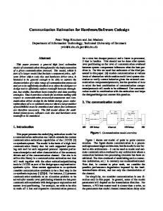
The user guided transformational methodology assumes that the designer starts with an initial speci cation and an architectural solution in mind. System design from speci cation to implementation is performed through a set of primitives allowing the designer to transform the system, following an incremental re nement scheme, in a distributed model that matches the architectural solution. All the re nement transformations are performed automatically. The decisions are made by the designer who uses his knowledge and experience to achieve the desired solution. Each step reduces the gap between speci cation and realization by xing some implementation details (communication protocol, generating software or hardware code) or by preparing future implementation steps (merging and scheduling several processes to execute them in a single processor). The transformations must satisfy the designer's imposed constraints without changing the functionality of the system. In the case of Cosmos, the user guided transformational approach makes use of three speci cation formats as shown in Figure 1. The initial speci cation is given in the system-level speci cation language SDL. The user controls the re nement process through a set of transformation primitives. All the re nement process is based on an intermediate form called Solar. The output is a virtual prototype of the architecture given in a distributed C/VHDL model. Within Cosmos, the partitioning steps are implemented through a set of primitives that performs basic transformations such as split, merge, move, at and map. The system provides three sets of primitives working on the system structure, behavior and communication. The designer guides the interaction process and chooses the transformations needed in order
SDL
SOLAR
INITIAL SPECIFICATION
C
INTERMEDIATE MODEL
VHDL INCREMENTAL
VIRTUAL PROTOTYPE
REFINEMENT
ARCHITECTURE
Figure 1: Speci cation models. to obtain the desired solution. A new implementation can be obtained by changing the primitives sequence activation. The organization of partitioning into several small steps reduces the complexity of the problem. The designer controls the partitioning history within an interactive environment, through ne grain control of the synthesis process. This methodology can be seen as a human guided compilation where the designer spends additional e�ort to produce an e�cient implementation ([18]). The designer has good design process control. To facilitate the user's interaction for incremental transformations, a graphical interface has been developed.
3 Internal Design Representations
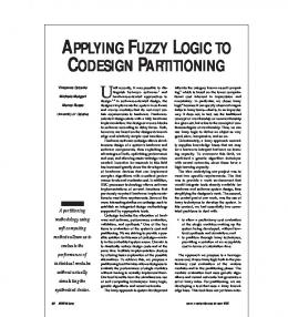
This section introduces a design model, called Solar, used for transformational partitioning ([16]). The di�erent re nement steps use Solar as an intermediate representation. Each step makes transformations on a Solar model. Solar supports high-level communication concepts including channels and global variables shared over concurrent processes. It is possible to model most system-level communication schemes such as message passing, shared resources and other more complex protocols. Solar models system-level constructions in a synthesis-oriented manner. The underlying model combines two powerful system-level concepts: extended nite state machine (EFSM) for behavioral description and, remote procedure call (RPC) for the speci cation of high-level communication (Figure 2). Design Unit Design Unit
Design Unit SEND
State Table
GET
PUT
State RECETable IVE
RESET
Remote Procedure Call Channel Unit
PROTOCOL
Channel Unit
PROTOCOL
Figure 2: EFSMs using RPC communication. The basic concepts are: State Tables, Design Units and Channel Units. � The State Table is the basic constructor for be-
�
�
havior descriptions. A state table is an EFSM composed of an unlimited combination of states and state tables (behavioral hierarchy). All of these states can be executed sequentially, concurrently, or both. A state table has attributes to handle exceptions, global variables, reset and default states. Transitions between states are not level restricted. In other words, transitions may traverse hierarchical boundaries (global transitions). The Design Unit construct allows the structuring of a system description into a set of interacting subsystems (processes). These subsystems interact with the environment using a well de ned boundary. A design unit can be speci ed as a set of communicating design units (structural hierarchy) or as a set of interacting state tables. The communication between design units can be performed in two di�erent ways, rst by means of classic port concept where single wires send data in one or two directions or by means of communication channels with a well de ned protocol. The Channel Unit performs the communication between any number of design units. The model mixes the principles of monitors and message passing, also known as remote procedure call ([2]). The use of a RPC to invoke channel services allows a exible representation, with a clear semantic. These communication schemes can be described separately from the rest of the system, allowing modular design and speci cation. A channel unit consists of many individual connections and it acts not only as a transport mechanism for the communicated data, it also provides a handshaking interface to ensure both the synchronization and the avoidance of access con icts. The channel is composed of a controller, a set of methods and a set of interconnected signals. The controller stores the resource's current state. The access to the channel is governed by a xed set of methods (services) that are the visible part of the channel. The utilization of an extensible library of protocols permits the reuse of existing components. If a communication unit that implements the protocol, services and average rate required is not found in the library, the designer can adapt an existing communication unit (increase the bus width or bu�er size for example) rather than building from scratch.
4 Transformation Primitives
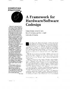
The partitioning process is composed of three types of transformations, these are: functional decomposition, structural reorganization and communication transformation. Functional decomposition acts on the state tables to allow re ned behavioral descriptions. Structural reorganization acts on design units to allow re ned structure of the system. Communication transformation acts on channel units to allow re ned communication protocols. All these re nements make use of a set of ve primitives called split, merge, move,
at and map to decompose, compose and transform Solar objects. Figure 3 summarizes these partitioning primitives. Functional
Interactive Decomposition Partitioning State Table
Structural Reorganisation
Design Unit a
st s1
Communication Transformation
Channel Unit
st
s1
s2
s2
Split
st
a
s1
s2
idle
idle
a1
st s1
a2
a
b
a
b
ab a
b
a
b
s2
Merge st
s12
a
st s1
c d
b
s2
e
Move a
st s1
s2
s1
s2
c d
b
a st
e
c d
b
e
Flat st
a s1
s2
c
b
e
a
b
a [Hw]
b [Sw]
Map
a
b
a
b
Conttr.
Figure 3: Decomposition, reorganization and communication primitives For each transformation an applicability condition is associated. It de nes constraints on the application of the transformations. Before the application of any transformation requested by the designer, the system checks the applicability conditions. The designer can apply the primitives in any order as long as the application conditions of these primitives are ful lled.
5 Functional Decomposition
The functional decomposition primitives are used to transform behaviors i.e. state tables. A brief description follows (the term machine is used to represent a state or a state table): � Split: decompose a sequential machine into a set of sub-machines. Each resulting machine can be placed in a di�erent partition. Control signals and wait states are added to each machine to represent the revised process control. � Merge: groups a set sequential machines into a unique machine to permit the sharing of resources (registers and functional units). � Move: transforms the hierarchy of a given machine. It can be used to move a code from a
�
software realization to a hardware realization and vice-versa. Flat: atten a machine's hierarchy.
5.1 Structural Reorganization
The structural re nement goal is to distribute the behavior into a set of design units that correspond to the nal processors. In this case, the application of these primitives transforms the structure hierarchy. Each primitive may be applied several times during structural reorganization. These primitives realize also an automatic reorganization of the interconnection between modules. Hereby follows a description of the structural reorganization primitives: � Split: works on the behavior of parallel processes (state tables) in order to split then into a set of independent modules (design units). Each module will communicate with the others by means of I/O signals and channels. The data shared between the split machines (global variables) are converted to abstract channels in the new representation. These abstract channels are usually mapped to a shared variable communication protocol. In each generated module, global variable accesses are replaced by calls to remote services o�ered by a channel. Basically a channel's read and write services are used to access these variables. � Merge: groups a set of modules into a new design unit. This operation is generally used to cluster the modules that will be assigned to the same processor into a single design unit. � Move: moves a design unit in the hierarchy. This primitive is usually used to prepare a merge operation. � Map: permits the identi cation of hardware and software realization options for each process. � Flat: performs a structural attening operation on the hierarchy.
5.2 Communication Transformation
This step transforms a system composed of processes that communicate via high-level primitives (through abstract channels) into interconnected processes that communicate via signals. Cosmos makes use of a channel library composed of basic protocol templates. Two primitives are available for the communication transformation: � Map: assign a physical communication unit to each high-level communication channel and generate the interfaces between the interconnected units. � Merge: allows replacement of two or more abstract channels by another abstract channel. In several cases this leads to a cost reduction. The application of this transformation is restricted, the resulting channel needs to have an implementation in the library.
6 Applications
This section details the application of the transformational approach to a co-design example, a Robot Arm Controller. In this example we will illustrate the overall design ow of Cosmos, from a systemlevel speci cation given in SDL to a distributed hardware/software architecture described in C/VHDL. The use of SDL allows for vefold reduction of the size of system speci cation when compared to distributed C/VHDL models. All the transformations applied in this section are fast enough to look instantaneous during an interactive session. None of the primitives require more than 5 seconds CPU time on a Sparc 20 workstation.
6.1 Robot Arm Controller example
The Robot Arm Controller is a system that adjust the position and speed parameters of eighteen motors belonging to a robot arm with three ngers. This computation is intended to avoid discontinuous motor operation problems. The change in a motor's speed should follow a smooth curve for acceleration and deceleration for mechanical reasons. This application requires that the system react in less than 6 ms. The basic block diagrams of this system, in SDL, is shown in Figure 4. Figure 4.a shows the overall process and blocks hierarchy of the SDL description. Figure 4.b shows a graphical representation of the top level of hierarchy of the SDL model. The system is made of three blocks that interacts through channels. Figure 4.c details the organization of the AdaptativeSpeedControl block into three processes communicating through \signalroute". These gures are made using a commercial SDL environment called ObjectGeode ([21]). In a brief functional description, the AdaptativeSpeedControl block receives positions from the HostMachine block. The AdaptativeSpeedControl calculates the speed required for each motor in order to make all the motors reaching the desired position at the same time. The motor with the longest distance to go runs at the maximal speed and the speed of the other motors are adapted to this one. The output speed desired for each motor is send in the form of speed control pulses to the MotorSender block. This block converts the pulses into control signals to each motor. The main blocks of this speci cation are: � HostMachine process is the interface between the user and the system, it takes care of segment storage and motors' constants calculation. � DistanceCalculation stores up to date information about the distance to go for every motor according to the current position. � DistributionControl process identi es the motor that must run at maximal speed and sends scaled commands to the other controllers. � SpeedControl process converts the input steps into a curve that respects the worst case maximum
(a) System structure
(b) ’Robot_Arm_Controller’ process structure
(a) ‘Robot_Arm_Controller’ structure
(b) ‘AdaptativeSpeedControl’ structure
(c) Results of structural Flat, Merge and channel Map
(c) ’AdaptativeSpeedControl’ block structure
Figure 4: Input SDL representation. load acceleration and deceleration curves of the motors. � MotorSender is the interface to the stepper motors that converts the speed into frequency pulses. The constraints for this design are: the time needed to complete the total movement must be minimal, the change in velocity must be as smooth as possible and the overshoot at the end position must be minimal. The SpeedControl block is responsible for computing the number of speed control pulses with a speci ed nal position and a current state of a motor. This block contains a digital lter based on a Fuzzy Logic algorithm to generate the smooth acceleration curve. During partitioning the SpeedControl and the MotorSender blocks were assigned to hardware and the other blocks to software. In this architecture implementation, the processes with extensive computation were assigned to have a hardware implementation to respect the system time constraints. Figure 5 shows the use of re nement primitives on the Solar representation. The results of the re nement steps is shown in Solar graphical representation. Figure 5.a-b shows the structure of the initial SDL model when translated into Solar. In this model, boxes represent design units, lines represent wires and bold lines represent channels. Figure 5.c shows the result of a set of transformations, including at and merge operations on the initial structure and, merge and map on the channels. The abstract channels were mapped on protocols from the library. In Figure 5.d-e we can see a graphical representation of the nite state machines resulting after the application of the structural merge operations.
(d) Behavior of the software part
(e) Behavior of the hardware part
Figure 5: Re nement steps. In Solar, the behavior is represented by state tables and shown as a hierarchy of nested boxes where each box represent a state or a state table. The SpeedControl and MotorSender blocks are allocated eighteen times. An instance for each motor was necessary to arrive at the desired throughput. In Figure 6 we can see the nal system structure and parts of the generated C/VHDL code. In this example, the descriptions size in number of lines were: 717 lines for the SDL initial input, 2848 lines for the resulting C le resulted and, 853 lines in VHDL for each motor instance.
7 Evaluation
This work is related to design methodology for mixed hardware/software system. Our objective has been to bridge the link between the system-level spec-
(a) ’Robot_Arm_Controller’ final structure
sign examination and control over the operation
ow. 3. Use of designer expertise: If the designer has a solution in mind he/she can force it through the use of the appropriate sequence of transformations. The initial solutions obtained by the system can be used by the designer in order to explore new solutions. 4. Design exploration of implementation options: The user guided transformational approach allows the user to force the co-design process in order to obtain a given solution. The Cosmos system is fast enough to allow the exploration of several solutions. The main limitation of the present version is the lack of good and reliable estimation functions. In present version the user needs to produce a C/VHDL model in order to have a realistic estimation of his solution.
8 Conclusion
(b) Partial C-code of ’distancecalculation’ process
(c) Partial VHDL-code of ’speedcontrol’ process
Figure 6: Virtual prototype. i cation and hardware/software architecture design, providing a short design time and fast exploration of the design space. In order to achieve this goal we employ a user guided transformational approach. The co-design methodology described for incremental re nement satis es the challenges outlined in Section I.A, we have: 1. Semi-automatic approach to partition a functional speci cation: The designer's interaction is though needed because realistic estimation methods are not available. It is possible to manipulate complex systems in a wide range of application domains. 2. Predictability of partitioning results: The user selects the elements that will be transformed by each operation. The result is immediately obtained and a graphical viewer permits a quick de-
We presented a realistic semi-automatic methodology for co-design capable to handle multiprocessor distributed systems. This methodology is based on a powerful set of primitives for functional partitioning, structural reorganization and communication transformation. The co-design starts with a system-level speci cation given in SDL. This initial model is re ned through a user guided compilation process in order to produce a distributed hardware/software architecture described in C/VHDL. The use of this approach was illustrated through an example. In contrast with other co-design approaches, the transformational approach provides an elegant solution for the main challenges imposed by co-design of distributed systems, i.e. 1. using the expertise of the designer for partitioning; 2. allowing the user to understand the details of the co-design process; 3. taking into account partial solutions; 4. fast exploration of the co-design space.
Acknowledgments
This work was supported by: France Telecom/CNET under Grant 941B113; SGS-Thomson; Esprit program under project COMITY (23015) and project CODAC (OMI 24129) and; MEDEA program under project SMT AT403.
References
[1] M. Abid, A. Changuel, A. A. Jerraya, Exploration of Hardware/Software Design Space Through a Codesign of Robot Arm Controller, In Proceedings European Design Automation Conference with EURO-VHDL'96, Geneva, Switzerland, pp. 42-47, September 1996.
[2] Andrews, Concurrent Programming, Principles and Practice, Benjamin/Cummings (eds), Redwood City, Calif., pp. 484-494, 1991. [3] E. Barros, W. Rosentiel, X. Xiong, A Method for Partitioning UNITY Language in Hardware and Software, Proceedings of European Design Automation Conference (Euro-DAC), 1994. [4] T. Ben-Ismail, K. O'Brien, A. A. Jerraya, PARTIF: Interactive System-level Partitioning, VLSI Design Vol. 3 no 3-4, pp. 333-345, 1995. [5] K. Buchenrieder, A Prototyping Environment for Control-Oriented HW/SW Systems using StateCharts, Activity-Charts and FPGA's, Proceedings of European Design Automation Conference with Euro-VHDL, Grenoble, France, pp. 60-65, September 1994. [6] J. Buck, S. Ha, E. Lee, Ptolemy: A framework for simulating and prototyping heterogeneous systems, International Journal of Computer Simulation, January 1994. [7] P. Camurati, F. Corno, P. Prinetto, C. Bayol, B. Soulas, System-Level Modeling and Veri cation: A Comprehensive Design Methodology, Proceedings European Design & Test Conference (EDACETC-EuroASIC), Paris, France, February 1994. [8] M. Chiodo, D. Engels, A. Vincentelli, A case Study in Computer Aided Codesign of Embedded Controllers, Design Automation for Embedded Systems, Vol. 1, No. 1-2, pp. 51-67, January 1996. [9] J. M. Daveau, T. Ben-Ismail, G. F. Marchioro, A. A. Jerraya, Protocol Selection and Interface Generation for HW-SW Codesign, IEEE Transactions on VLSI Systems, Special issue on Design Automation of complex integrated systems, September 1996. [10] DeMan, I. Bolsens, B. Lin, K. Van-Rompaey, S. Vercauteren, D. Verkest, Co-design for DSP systems, NATO ASI Hardware/Software Codesign, Tremezzo, June 1995. [11] R. Ernst, J. Henkel, Th. Benner, M. Trawny, The COSYMA Environment for Hardware/Software Cosynthesis, Journal of Microprocessors and Microsystems, Butterworth-Heinemann, 1995. [12] D. Gajski, F. Vahid, S. Narayan, J. Gong, Speci cation and Design of Embedded Systems, PrenticeHall, Inc. Englewood Cli�s, New Jersey, 1994. [13] J. Gong, D. Gajski, S. Narayan, Software Estimation from Executable Speci cations, Proceedings European Design & Automation Conference (EuroDAC), IEEE CS Press, Grenoble, France, September 1994. [14] R. Gupta, G. DeMicheli, Hardware-Software Cosynthesis using Reprogrammable Components, IEEE Design & Test of Computers, vol. 10, n. 3, pp. 29-41, September 1993.
[15] D. Harel, Statecharts: a Visual Formalism for Complex Systems, Science of Computer Programming, n. 8, North-Holland, pp. 231-274, 1987. [16] A. A. Jerraya, K. O'Brien, Solar: An Intermediate Format for System-Level Modeling and Synthesis, in "Computer Aided Software/Hardware Engineering", J. Rozenblit, K. Buchenrieder (eds), IEEE Press, Piscataway, N. J. , pp. 147-175, 1994. [17] A. Kalavade, E. A. Lee, The Extended Partitioning Problem: Hardware/Software Mapping, Scheduling, and Implementation-bin Selection, Proceedings of Sixth Workshop on Rapid Systems Prototyping, pp. 12-18, June 1995. [18] C. W. Krueger, Software Reuse, ACM Computing Surveys, vol. 24, no. 2, pp. 131-183, June 1992. [19] E. D. Lagnese, D. E. Thomas, Architectural partitioning of system-level synthesis of integrated circuits, IEEE Trans. CAD/ICAS, vol. 10, no. 7, pp. 847-860, July 1991. [20] P. Marwedel, G. Goessens, Code Generation for Embedded Processors (DSP), Kluwer Academic Publishers, 1995. [21] ObjectGeode, http://www.verilogusa.com/og/og.html. [22] P. Paulin, C. Liem, T. May, S. Sutarwala, DSP Design Tool Requirements for Embedded Systems: A Telecommunication Industrial Perspective, in Journal of VLSI Signal Processing (special issue on synthesis for real-time DSP), Kluwer Academic Publishers, 1994. [23] R. Saracco, P. A. Tilanus, CCITT SDL: an Overview of the Language and its Applications' Computer Networks and ISDN Systems, Special issue on CCITT SDL, vol. 13 No 2, pp. 65-74, 1987. [24] M. Srivastava, R. Brodersen, SIERA: A uni ed framework for rapid-prototyping of systemlevel hardware and software, IEEE Transactions on Computer-Aided Design of Integrated Circuits and Systems, pp. 676-693, June 1995. [25] P. A. Subrahmanyam, W. Wolf, HardwareSoftware Codesign for Embedded Systems, in ASP-DAC'95, Makuhari Messe, Chiba, Japan. pp. 1-72, 1995. [26] C. A. Valderrama, A uni ed model for cosimulation and co-synthesis of mixed hardware/software systems, ED&TC'95, Paris France, 6-9 March 1995. [27] W. Wolf, Hardware-Software Co-Design of Embedded Systems, PROCEEDINGS OF THE IEEE, vol. 82, no. 7, pp. 967-989, July 1994. [28] W. Wolf, Object-Oriented Co-Synthesis of Distributed Embedded Systems, in Proceedings CHDL'95, IFIP, 1995.