Author manuscript, published in "6th International Conference on Field and Service Robotics - FSR 2007, Chamonix : France (2007)"
Tree Measurement and Simultaneous Localization and Mapping System for Forest Harvesters 2 ¨ Matti Ohman , Mikko Miettinen2 , Kosti Kannas3 , Jaakko Jutila4 , Arto 5 Visala and Pekka Forsman6 1 2 3 4 5
inria-00258924, version 1 - 26 Feb 2008
6
Helsinki Helsinki Helsinki Helsinki Helsinki Helsinki
University University University University University University
of of of of of of
Technology Technology Technology Technology Technology Technology
(TKK) (TKK) (TKK) (TKK) (TKK) (TKK)
[email protected] [email protected] [email protected] [email protected] [email protected] [email protected]
Summary. For the last decades, measurement and automation systems in Nordic cut-to-length forestry machines have evolved gradually. These heavy duty machines are lighter, faster and more accurate than ever before but the basic technologies and operation have remained the same. In many respects, their current automation systems have reached their limits. The Forestrix project studies how advances in mobile robotics could be applied in the field of forestry machine automation. Machine vision systems and scanning laser range finders have established themselves as standard equipment in mobile robotics. With the new sensor and computing technologies it is possible to get information about the surrounding forest, such as tree diameters, positions and stand density. This information can be used on-line in operator’s decision support system, or off-line in a forest asset management system. This paper describes the prototype measurement platform and the software algorithms developed in the Forestrix project. Results from tests with an all terrain vehicle are also presented.
1 Introduction The Forestrix project studies advanced sensor systems for forest harvesters. One of the sensors used is a scanning laser range finder (henceforth a laser scanner). As the machine is moving in the forest the laser scanner can take multiple scans of the trees it passes from different directions. This allows the measurement system to use stochastic models to greatly improve the quality of the collected information. However, combining the different measurements requires that the system is able to reliably relate the measurements to correct trees. In the literature this is known as the data association problem. It is easy to solve if the path of the moving sensor is known, in which case we
2
¨ Ohman, Miettinen, Kannas, Jutila, Visala, Forsman
inria-00258924, version 1 - 26 Feb 2008
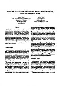
have a simple mapping problem. Unfortunately, the path cannot be directly measured without a very accurate and expensive navigation sensor, such as RTK-DGPS[1]. However, if the association problem can be solved without the exact sensor path, the sensor path can be calculated relative to the trees being measured. In the literature, this is known as the simultaneous localization and mapping (henceforth SLAM) problem. In the Forestrix project the laser scanner is used for SLAM[2]. A machine vision system is used to augment the map generated by the SLAM algorithm. With the help of the laser scanner, the machine vision system divides camera images into sub images. Each sub image contains one dominant tree trunk. Different edge detection algorithms are used to extract the vertical edges of the dominant tree trunk. Using a calibrated camera and range information from the laser scanner, it should be possible to measure the actual diameter of the tree trunk with greater accuracy that is attainable with a laser scanner alone. The machine vision system should also be able to identify the tree type i.e. whether it is pine, spruce, birch, or other deciduous tree. This additional information should be stored in the tree map that is incrementally built by the SLAM algorithm. 1.1 Data Collection System The data collection system consists of 2D and 3D laser scanners, machine vision camera, differential GPS receiver, MEMS inertial measurement unit and PC computer. The 2D laser scanner is used continuously while the 3D laser scanner is used only for reference measurements while the platform is stationary. The 3D scanner is unsuitable for continuous measurements because it takes several minutes to create a single 3D scan. The data collection system is build on an all terrain vehicle which is shown in Figure 1.
Fig. 1. ATV test platform
Tree Measurement and SLAM System for Forest Harvesters
3
The machine vision camera is synchronized to the 2D scanner. A special hardware frequency divider is used to transform the synchronization signal from the laser scanner so that it can be used to trigger the camera which operates at a much lower frequency. The differential GPS is the same model that is commonly used in forest harvesters. It has higher sensitivity than most consumer level receivers so that it can maintain better satellite fix even in demanding forest environments. MEMS inertial measurement unit is used to provide information of the pose of the platform.
inria-00258924, version 1 - 26 Feb 2008
2 Feature Based SLAM The overall structure of the feature based SLAM algorithm is shown in Figure 2. The SLAM is based on the raw 2D laser scanner data. The first step is the feature extraction. In this application, the features are the surrounding trees. The tree features identified from a single scan are called echoes due to their uncertain nature. In a clean forest with little or no underbrush it is a relatively simple task to find the tree trunks from the raw laser scans. An example scan and its segmentation are shown in Figure 3. However, in more dense forests, finding the trunks can be extremely difficult if not impossible. The dense vegetation also reduces the effective measurement range drastically. Even in relatively clean forests the blind areas behind the nearest trunks can be substantial.
Raw Laser Data
Echo Extraction
Nearest Neighbour Search
Projection to Map Coordinates
Updating Tree Graph • new nodes • old nodes
Updating Tree Graph • new edges • old edges
Old Pose Estimate
New Pose Estimate
Matching Echos to Trees
Estimating New Pose
Fig. 2. Information flow in feature based SLAM
While it is straightforward to extract the echoes from the raw scans, it is very difficult to identify individual trees. This problem of matching features is usually referred as the association problem in the SLAM literature. Many SLAM applications get around of this problem by using beacons that can
4
¨ Ohman, Miettinen, Kannas, Jutila, Visala, Forsman
be unambiguously identified. However, this approach is not feasible in the proposed forest mapping application. A single tree trunk is difficult to identify because they all look the same for the laser scanner. Even the variation of trunk diameter can be very small in a well managed forest.
inria-00258924, version 1 - 26 Feb 2008
Fig. 3. The segmentation of a single scan from a well-managed pine forest
2.1 Tree Group Matching Instead of trying to identify individual trees, it is better to identify groups of trees. These groups are identified in the third step in Figure 2. The tree groups offer a variety of features that can be used for identification: distances and angles between adjacent trees and trunk diameters. One of the central challenges in this approach is that the tree groups are not constant. Depending on current position, not all trees may be visible because of the blind areas. For this reason, the tree groups are formed dynamically based on locality: a tree and its nearest neighbors form a group. Group sizes from six to eleven have been tested. The angular resolution is of the laser scanner is 1 , 0.5 , or 0.25 degrees depending on its operating mode. The measurement uncertainties make it harder to identify trees at greater distances. The matching of echoes to the tree map is done in the fourth step. The matching is done a group at a time starting with the closest one. The tree map is stored as a graph structure which makes this a graph matching problem. However, there are some issues that will have to be taken into account. First, the echo graphs are usually incomplete because of the blind areas. Second, also the tree graph is usually incomplete, because the map is incrementally built. The matching algorithm uses distances between adjacent tree trunks to match tree groups. Distances between trees are easy to work with because they are translation and rotation invariant. Relative angles are more difficult
Tree Measurement and SLAM System for Forest Harvesters
5
to work with because they need an additional reference point. If three trees are matched together in a triangular configuration, as shown in Figure 4, the distance information alone describes the full geometry making the relative angles completely redundant. For this reason, the relative angles are not used for matching tree groups. Absolute angles (e.g. relative to magnetic North) could be useful for matching purposes, but the current sensor platform does not have a reliable and accurate instrument for measuring absolute angles.
inria-00258924, version 1 - 26 Feb 2008
Fig. 4. Distances and relative angles contain the same information
After the echoes have been matched to trees, a simple algorithm is used to estimate the new pose. First, the ”centers of gravities” of both set of points are calculated and the echo set is then translated so that the CoGs coincide. Second, the average angle between all echo-tree pairs is calculated and the echo set is then rotated by this angle. Care should be taken that all the angles are calculated on the correct cycle. This algorithm is based on the realistic assumption that the subsequent scans differ only by a translation and a rotation. 2.2 Tree Graph Updates In the final phases the echoes are projected to map coordinates. At this point they are classified either as new or old trees. New trees are added to the tree graph and diameter information is accumulated to old trees. The closer the scan is taken, the better the diameter information usually is. New edges are also inserted into the tree graph and old edges are updated to reflect the new information. Currently only the distances between the trees are recorded but later angles will be used as well. One of the problems of the presented algorithm is that it makes the optimistic assumption that all echoes really are trees. This helps the algorithm to acquire new trees and to keep going, but if echoes of branches are falsely interpreted as trees they will be added permanently to the tree map. To solve this problem another algorithm was added to remove false positives from the tree map. The principle of this algorithm is shown in Figure 5. The algorithm works by projecting laser scans to map coordinates and then using a collision detection algorithm to find intersections between the ”rays” and the trees in the map. If there are more ”rays” passing through a tree than there are valid measurements of that tree, the tree is removed from
6
¨ Ohman, Miettinen, Kannas, Jutila, Visala, Forsman
Raw Laser Data
Projection to Map Coordinates
Collision Detection
Updating Tree Graph • removing nodes
Fig. 5. Removal of false trees in feature based SLAM
inria-00258924, version 1 - 26 Feb 2008
the map. This second algorithm was added as an afterthought and it reflects the inability of the first algorithm to record what is sometimes referred as negative information. Future improvements of the algorithm may use local occupancy grids to keep track of areas that are known to be free of trees. The tree graph is a hybrid data structure. The graph structure contains the nodes and the edges between them. Each edge has length and in future versions also direction. However, each node has also position in Cartesian coordinates. The possible mismatch between Cartesian positions and edge lengths can be used by a third algorithm to distribute the accumulated error evenly e.g. when a large loop is being closed. Currently this is done with a simple iterative algorithm that tries to minimize and distribute the tensions in the tree graph. 2.3 SLAM Results The current version of the software is written in the Java programming language. The software can read input data either from data files or from the actual sensors. The data files are essential for testing the system in a laboratory environment. The software can connect to the 2D laser scanner and the DGPS receiver. The SLAM path can be matched to the DGPS path. As a result the algorithm also gives the tree positions in absolute map coordinates. The resulting absolute accuracy is mostly limited by the DGPS receiver. A tree map produced by Forestrix SLAM is shown in Figure 6. The DGPS path is marked with a narrow line and the SLAM path is drawn with a bold line. Measured tree positions are also shown. These positions and diameters can be compared to hand measured tree information provided by METLA (Finnish Forest Research Institute). At a measurement distance of 1m, the maximum observed diameter error is 1cm. The error increases linearly with distance up to 10m, where it is 6cm. After that the error increases more rapidly. These tests were done using 0.5 laser scanner resolution. A higher 0.25 resolution is expected to improve performance. At this time the described SLAM algorithm works in well defined forests.
3 Machine Vision System Forest is one of the hardest environments for computer vision as it is extremely organic and unpredictable. It is structured in the sense that most trees grow
Tree Measurement and SLAM System for Forest Harvesters
7
inria-00258924, version 1 - 26 Feb 2008
Fig. 6. Tree map produced by Forestrix SLAM (the path is traversed twice)
in nearly vertical direction but otherwise the vegetation is very diverse in shape and density. The ground is not flat and there are arbitrarily shaped objects such as big rocks. The shooting is done in varying lighting and weather conditions and there are a lot of occlusion and shadows that complicate the situation. Taking images while moving introduces its own problems as well. 3.1 Tree Edge Extraction To measure the tree diameter from an image, the feature extraction algorithm has to find the edges that correspond to the borders of the tree. The problem is, despite of all the filtering, that there are usually many edges to choose from, and the correct edges are not necessarily the strongest ones. The contrast between occluded trees is usually very poor while the contrast between the lower part of the trees and the ground is generally quite good. Seasonal variation, weather, time of the day and many other aspects make sure fixed parameters cannot be used for feature extraction. There are many approaches to edge detection from traditional gradient based methods to neural networks and other more complex methods[3]. They are based on different assumptions and use different edge models or different optimality criteria. Assessing edge detector performance is difficult because there is no available ground truth of which pixels should really be edges and which not. Movement during exposure, uneven lighting, quantization errors and noise make the edges more difficult to detect. The feature extraction part of the implemented algorithm starts with optional homomorphic filtering followed by vertical Fourier filtering. After the filtering stage the algorithm has a choice of using either Canny[4] or phase congruency based edge detector[5], [6]. In the default setting the algorithm will first use Canny with no prior homomorphism. If the algorithm doesn’t seem to find enough features, it makes another pass with homomorphism enabled and
8
¨ Ohman, Miettinen, Kannas, Jutila, Visala, Forsman
inria-00258924, version 1 - 26 Feb 2008
Canny replaced by phase congruency edge detector. The Canny edge detector is chosen as the main edge detector here because it is well known and tested, it is fast and it performs well. The more advanced phase congruency based detector is chosen as an alternative approach which produces considerably different results than Canny. The idea is to tackle the easy situations quickly with Canny and try the phase congruency detector with the hard low contrast cases. The MATLAB implementations of both edge-detectors are made by Kovesi[7]. The Canny algorithm used here implements the enhancements proposed by Fleck[8]. The raw output of both edge detectors were iterated with varying hysteresis threshold values until enough edge features were detected. Figure 7 illustrates how phase congruency can manage low contrast situations better than Canny.
Fig. 7. A comparison between Canny edge detector algorithm (left) and phase congruency (right)
3.2 Tree Edge Selection For selection, the edges are projected to form a 1D signal. Choosing the right edges, when the data can be quite arbitrary, is the hardest part of the algorithm. In this approach, the strongest edge is selected first and it is matched with as strong edge as possible when constrained by the minimum and maximum estimates of the tree width provided by the laser scanner. The chosen edges are required to be more than 5 pixels strong. The final measuring point is chosen by taking into account the neighborhood of the chosen edge in a form of a weighted average filter. The size of the filter depends on the distance of the tree in question and can vary between 3 for trees far away to 9 bins for trees very near. Figure 8 shows how the left side edge is shifted more to the left because of its strong neighborhood (chosen points are marked with diamonds). This edge selection method totally loses the vertical dimension and
Tree Measurement and SLAM System for Forest Harvesters
9
inria-00258924, version 1 - 26 Feb 2008
assumes that the trees are positioned straight along the window. That is the price of a simplified approach. Lens distortions are corrected[9] for the chosen two points and the measurement is transformed to metric units with pinhole camera model and calibration information. Processing one image takes usually a few seconds with a mid-level PC.
Fig. 8. Edge selection from 1D signal (vertical pixel sum vs. x-axis pixel)
3.3 Machine Vision Results A data set of 191 images was analyzed with automatic batch processing and also with manual classification where unreliable cases were not included. In the hand picked case the mean diameter error is 20mm with 20mm standard deviation, while for the automatic processing the figures are 0.4mm and 34mm respectively. The automatic results are not as good as they seem as the maximum errors for diameters can be as large as 100mm, because the algorithm often measures something completely different than the desired tree. The reliability of the system does not meet any useable levels. However, the system has demonstrated that a laser scanner and a camera can work together in an intelligent and usable way. This research has also uncovered some fundamental problems of digital forest imaging and paved the way for further studies.
4 Conclusions and Future Work The current algorithms implemented in Java programming language run somewhat slower in modern laptop computers than what is required for real-time applications. Some parts of the presented SLAM algorithm can be easily tuned
10
¨ Ohman, Miettinen, Kannas, Jutila, Visala, Forsman
inria-00258924, version 1 - 26 Feb 2008
for better performance. Java is a safe language which makes it easy to program with but it is not the best programming language performance-wise. Also interfacing it with exotic hardware such as 2D laser scanners can be difficult. C++ implementation may have to be considered in later phases of the project. A forest is very tough environment for precision instruments. Luckily there are 2D laser scanners and DGPS receivers that are designed for outdoor use. The forest terrain is often quite rough, which adds additional challenge for the sensor system. It may be necessary to tilt the sensor package when the harvester is working in an inclined position or traversing slopes. More development work is needed to find better solutions to the association problem. The current system works well for small loops (50m x 100m). However, the accumulation of errors may be a problem for larger loops. Identifying trees may also be a problem in more dense and cluttered forest environments. Digital forest imaging has turned out to be very challenging research area, but it is essential for future forest mapping systems which will require features such as tree species recognition. Digital imaging systems have the ability to see textures and other tree qualities that laser scanners cannot perceive.
References 1. Hellstrm T, Johansson T, Ringdahl O, Georgsson F, Prorok K and Sandstrm U (2005) Development of an Autonomous Path Tracking Forest Machine. The 5th International Conference on Field and Service Robotics (FSR’05). Port Douglas, Australia, July 29–31 ¨ 2. Miettinen M, Ohman M, Visala A, Forsman P (2007) Simultaneous Localization and Mapping for Forest Harvesters. The 2007 IEEE International Conference on Robotics and Automation (ICRA’07). Rome, Italy, April 10–14 3. Ziou D and Tabbone S (1998) Edge detection techniques – an overview. International Journal of Pattern Recognition and Image Analysis 8:537–559 4. Canny J (1986) A computational approach to edge detection. IEEE Trans. Pattern Analysis and Machine Intelligence, 8:679-698 5. Kovesi P (1999) Image features from phase congruency. Videre: Journal of Computer Vision Research, vol. 1, num. 3 6. Kovesi P (2002) Edges are not just steps. The 5th Asian Conference on Computer Vision (ACCV’02), January 7. Kovesi P (2006) MATLAB and Octave functions for computer vision and image processing. School of Computer Science & Software Engineering, The University of Western Australia. http://www.csse.uwa.edu.au/∼pk/research/matlabfns/ (Referenced 4.12.2006) 8. Fleck M (1992) Some defects in finite-difference edge finders. IEEE Trans. Pattern Analysis and Machine Intelligence, vol. 14, num. 3, March 9. Mallon J and Whelan P (2004) Precise radial un-distortion of images. In: Proc. the 17th Int. Conf. on Pattern Recognition (ICPR’04)