Tuning Cascade PI(D) Controllers in PMDC Motor Drives: A Performance Comparison for Different Types of Tuning Methods Taha Nurettin G¨ucin1 , Muhammet Bibero˘glu1 , Bekir Fincan2 , Mehmet Onur G¨ulbahc¸e2 1
Energy Systems Engineering Department, Yalova University
[email protected],
[email protected] 2 Electrical Engineering Department, Istanbul Technical University,
[email protected],
[email protected] Abstract This work presents a comparison between different tuning methods for cascade PI(D) controller parameters of the permanent magnet direct current (PMDC) motor drives. First, the classical method (CM) for cascade PI(D) tuning is explained and applied. It has been shown that the classical tuning approach requires some assumptions. Next, a heuristic optimization technique, the Bacterial Foraging Algorithm (BFA), has been introduced and implemented for the problem. Lastly, for the comparison, the Genetic Algorithm (GA) is applied for the cascade PI(D) tuning problem. The results for these three methods are compared and discussed. It is shown that the controller designed by BFA showed better dynamic performance.
1. Introduction The PMDC machines have a simpler construction since the field winding of a DC motor is replaced by permanent magnet (PM). Consequently, they have become one of the most commonly used machines in many applications such as electric vehicles, robotic manipulators, trams or motion controller devices etc. [1] - [3]. Some of these applications require robustness, reliability and precision so that the process of tuning the controller parameters is of big importance. The proportional-integral-derivative (PID) controllers have been widely used for industrial processes due to their simplicity of operation and robust performance. Thus, tuning the PID parameters has been an attractive research area for a long time [4] - [7]. It is important to design a controller for restraining the speed of DC motor at desired the level under wide variable load conditions. On-off control firstly makes sense as the simplest control scheme but this control has less accuracy and stability. On the other hand, PID control method gives very accurate results for speed control but produces high starting current which can be dangerous for the motor and control circuitry. One of the best features of PID controllers is the ability of applying cascade PID configuration by using more PID blocks together. The cascaded PID configuration achieves a better dynamic performance, gives best point tracking, disturbance regulation and reduced starting current that can be used for low and high capacity motors when compared with single PID [8]. In this configuration, the controllers are placed in the manner that the input of one PID is controlled by another PID block. Mainly, cascaded control systems contain integrated sets of control loops. The advantages of cascade systems compared to single loop are flexibility, anti-jamming capability and rapidity. Moreover, this control configuration reduces the time con-
stant of the system [9]. Speed, torque, current and position of PMDC motor are generally controlled by cascade connected controllers. In these applications, PI controllers are preferred instead of PID controllers. However, it has still been a problem to achieve optimal PID parameters for both single and cascaded PID controllers due to fact that many plants are often saddled with problems such as high order, time delays, and nonlinearities [4]. When the cascaded loops are poorly tuned, the loops start influencing each other, oscillations occur and eventually neither variable is properly controlled. In order to tune cascade PID parameters, classical approaches make certain assumptions. Although, these approaches require a lot of insight on the plant and some precalculations, they are very fast when implemented to a computational software. On the other hand, due to the assumptions, the controllers may not result in the desired performance parameters or they may not deal with conditions that are not considered due to assumptions. Thus, usually a further tuning process is required [5]. Additionally, the PID parameters can be tuned by computational or optimization techniques such as artificial neural network, fuzzy logic, genetic algorithm and bacterial foraging algorithm, which are used for data modeling and optimization of a cost function [5, 6]. Kadiyala et al. have proposed a single loop PID controller for a current driven PMDC and applied particle swarm optimization (PSO) and bacterial foraging algorithm (BFA) in order to tune the PID parameters [10]. They have shown that BFA tuning method gives less overshoot and less steady state error. The study [11] has offered a BFA based PI controller for high speed permanent magnet synchronous machine speed control. They have shown that BFA based control works well in a wide speed range. Bhushan et al. have introduced BFA and genetic algorithm based speed control systems for a DC motor and compared the results of each method [12]. They have shown that BFA based controller works more effectively for tracking the desired trajectory with less computational time. Some of the researchers have studied the PID parameter tuning of servo systems based on Bacterial Foraging Algorithm. They have compared BFA with standard GA by simulations and shown that BFA has global search ability better than GA [13, 14]. Precup et al. have proposed BFO based tuning of both PID and sliding mode controllers for the shaft angle control of a pancake DC torque motor, which focused on minimizing an objective function expressed as the weighted sum of overshoot plus the integral of the squared (ISE) error. The PID controller parameters found by the BFO repeated for different numbers of bacteria population, and sliding mode controller parameters calculated for fixed and random swim steps [15]. In conclusion, a study,
which contributes to tuning the parameters of the cascade PID controllers by BFA in comparison with different methods, has not been included in the literature.
frequency of the Gcol (s). Thus, the integral and proportional constant of current control loop can be calculated using Eq. 4 and Eq. 6.
2. Classical PI(D) Tuning Method In this section, the guidelines of [16] are followed and modified. The general control system is illustrated in Fig. 1. Here, controller transfer function is Gc (s) and system transfer function is Gs (s). The open loop transfer function Gol (s) is obtained using Eq. 1. The amplitude of the open loop transfer function at crossover frequency is supposed to be 1.
X ∗ (s)
Gs (s)
Gc (s)
(1) X(s)
Firstly, the current control loop, the innermost loop, is interpreted. The current and torque are proportional in PMDC motor because of constant field flux so that the current can be considered as a control element. The current control loop seen in the Fig. 2 is simplified by neglecting the load torque, TL , acting as T disturbance and writing s.Jkme k+B instead of back electromom tive force (EMF), Ea (s). If the mechanical inertia, Jm is big enough, the effect of Ea (s) can be neglected. As a result, the simplified current control loop seen in the Fig. 3 is obtained. PI
V (s)
1 sLa +Ra
Ia (s)
Te
kT
Ea (s)
1 sJm +Bm
kic s.Ra
(5)
kic = ωcc Ra
(6)
PI
Ia∗ (s)
1
Ia (s)
kT
Te (s)
1 sJm +Bm
ωm (s)
Figure 4. Speed Control Loop.
Figure 1. The Control System.
Ia∗ (s)
(4)
Gcol (s) =
∗ ωm (s)
Gol |wc = Gc (s)|wc .Gs (s)|wc = 1
1 τe
kic /kpc =
Secondly, the speed control loop is reviewed. According to Fig. 4, the open loop transfer function of this loop, Gsol (s), can be written like in Eq. 7. Due to the designed current controller (by pole cancellation) the current reference is successfully followed by the controlled system. Here, kis is the integral constant, whereas kps is the proportional constant of the controller. The mechanical time constant, τm , is calculated using Eq. 8. The Eq. 9 is used to cancel the pole of the open loop transfer function seen in Eq. 7, a process similar to the one in current loop. Next, Gsol (s) becomes like Eq. 10. Finally, Eq. 11 is obtained in accordance with Eq. 1. Thus, kis and kps can be calculated using Eq. 9 and Eq. 11. The crossover frequency of the speed control loop, ωcs can be chosen to be 10 times smaller then ωcc .
ωm (s)
Gsol (s) =
TL
1/Bm kT .kis s (1 + k ) is s 1 + 1/τs m k
(7)
ps
ke
Jm Bm 1 kis /kps = τm kis kT Gsol (s) = s.Bm kis kT ωcs = Bm τm =
Figure 2. The Current Control Loop.
Ia∗ (s)
kic s
(1 +
s ) kic /kpc
Va (s)
1 sLa +Ra
Ia (s)
Figure 3. Simplified Current Control Loop. The open loop transfer function of the current control loop, Gcol (s), of Fig. 3 can be written like in Eq. 2. Here, kic is the integral constant, kpc is the proportional constant of the controller and the electrical time constant, τe , is calculated using Eq. 3.
(2)
La Ra
(3)
τe =
The Eq. 4 is used to cancel the pole of the Gcol (s), which is formulated in Eq. 2. After the pole cancellation Gcol (s) can be expressed as in Eq. 5. Finally, Eq. 6 is obtained in accordance with Eq. 1. The ωcc in this equation is defined as the crossover
(9) (10) (11)
The position control loop is illustrated in Fig. 5. Due to the designed speed controller (by pole cancellation) the speed reference is successfully followed by the controlled system. The open loop transfer function of position control loop is given in Eq. 12. Due to the presence of an integrator in the open loop transfer function, Gpol (s), only a proportional controller is sufficient for position control loop. ∗ θm (s)
1/Ra kic s Gcol (s) = (1 + ) s s kic /kpc 1 + 1/τ e
(8)
kpp
∗ ωm (s)
1
ωm (s)
1 s
θm (s)
Figure 5. Position Control Loop. The proportional constant, kpp , as seen in Eq. 13 is equal to the crossover frequency position control loop, ωcp , in account of Eq. 1. The ωcp can be chosen ten times smaller than ωcs .
kpp s = ωcp
Gpol (s) = kpp
(12) (13)
In this method, the system response to control input is accurate, as long as the input is a step function. Nevertheless, it is evidently seen that the steady state error is present if the input signal is a ramp function, parabolic function or a function of higher levels. The value of wcc should be chosen according to the switching frequency of the system. For example, when a DC machine is driven by a DC-chopper, it would be a reasonable approach to choose wcc to be ten times lower than switching frequency of the chopper.
3. Bacterial Foraging Algorithm The BFA originates from the phenomenon of the bacterial chemotaxis which is basically the movement of the bacteria in a solution with the purpose of finding nutrition. In a chemical solution, bacteria constantly detect the concentration of chemical substances and adjust their directions accordingly. Their movement can be categorized into two classes: swimming and tumbling. The major difference between these two movements is that the swimming is movement in which the bacteria intends to move towards a direction, whereas the tumbling represents a movement towards a random direction. As the bacteria constantly compare the amount of chemical substances in the previous and current steps, they detect the concentration change of beneficial or harmful substances. If an increasing concentration of beneficial substances are detected, they intend to increase the swimming cycle and to reduce the tumbling process. Therefore, a movement towards the area, where the concentrations of beneficial substances are high, is ensured. Consequently, this behaviour also ensures the drifting away from the area with higher concentrations of harmful substances. The BFA is comprised of three major mechanisms which are chemotaxis, reproduction and elimination-dispersion [14].
increases the oppurtinity for finding the global optima. This mechanism involves a certain amount of randomly chosen bacteria to be killed and replaced to other positions. Ned is the repetation number of reproduction stage.
4. Genetic Algorithm Genetic algorithm (GA) is a heuristic search that is inspired by natural evolution such as mutation, inheritance, crossover etc. This algorithm is usually used to achieve convenient solutions for the optimization and search problems [6]. The GA begins to search a random population. Almost 20100 individuals are selected for random population. This random population is also performed by real valued number or binary string called chromosome. The evolution begins with generating a random population, which is an iterative process called generation. The fitness of every individual, which is a predetermined objective/fitness function, is calculated at each generation step. The individuals with better fitness conditions are stochastically selected. Recombination and random mutation processes performed on the genome of each selected individual create a new generation. Generally, this process is repeated until the maximum number of generations has been produced or an desired result for the fitness function has been reached for the population [7].
5. Design Examples 5.1. Parameters For the PMDC motor, the parameters given in Table 1. are used. The PMDC model, shown in Fig. 6, is implemented in Matlab-Simulink. The Fig. 7 illustrates the cascade PI(D) control of the PMDC motor. V (s)
1 sLa +Ra
Ia (s)
Ea (s)
Te
kT
1 sJm +Bm
ωm (s)
TL ke
Figure 6. The Block diagram of the PMDC motor. 3.1. Chemotaxis As mentioned previously, moving a unit in random direction is tumbling, whereas moving a unit in the same direction of the last step is swimming. Swimming occurs if the result of the fitness function is getting better by the last step. Otherwise, the swimming stops and bacterium tumbles. NC is the maximum step number in a chemotaxis process. NS is the maximum number of swimming steps. 3.2. Reproduction Throughout the whole life of each bacteria, the sum of all step fitness functions are recorded. These represent the health status of each bacteria. In the reproduction stage, only the healthiest half of bacteria are retained, while others are killed. Then, new bacteria are placed in the same locations of the remaining healthiest ones. This stage ensures that the solution is converging to the optimal areas. Nre is the repetation number of reproduction stage.
Table 1. Parameters of PMDC Motor Motor Parameters
Value
Torque Constant
K = 2.35 N m/rad
Armature Inductance
La = 2.61 ∗ 10−3 H
Armature Resistance
Ra = 2.61 Ω
Inertia of the Motor
Jm = 0.068 kg.m2
Friction Constant
Bm = 0.008
Nominal Load
17.6 N m
Nominal Voltage
230 V
5.2. Implementation of the Methods 5.2.1. Design by Classical PI(D) Tuning Method
3.3. Elimination-Dispersion The first two mechanisms are not enough for bacteria to avoide the local optima. The elimination-dispersion mechanism
For the calculation with the classical approach, the parameters are chosen to achieve a critically damped system with no overshoot and the fastest settling time possible.
∗ θm (s)
P
θm (s)
∗ ωm (s)
PI
Ia∗ (s)
PI
V (s)
ωm (s)
1 sLa +Ra
Ia (s)
Te
kT
Ea (s)
ωm (s)
1 sJm +Bm
TL ke 1 s
Figure 7. Illustration of the cascade PI(D) controller implementation for PMDC motor. Table 3. Parameters of Genetic Algorithm Method
5.2.2. Design by Bacterial Foraging Algorithm The BFA mentioned previously is written in MATLAB code. The code runs the simulated PMDC motor and checks the fitness function, which is one of the most critical steps. Authors preferred to use the integral time-weighted absolute error (ITSE), steady-state error (SSE) and system overshoot. Each criteria is summed up by multiplying with a preferred weight coefficient. The coefficients are ”1” for each parameter. Table 2. contains the values of the parameters used for the BFA. F = ”IT SE” + ”overshoot” + ”steady state error” (14) Table 2. Parameters of Bacterial Foraging Algorithm BFA Property
Value
Number of Bacteria
50
Number of Chemotic Steps
10
Maximum Number of Swimming Steps
10
Number of Reproduction Steps
10
Number of Elimination-Dispersion Steps
5
Probability of Elimination
0.2
5.2.3. Design by Genetic Algorithm In this paper, the GA Toolbox of Matlab is used for optimization of controller parameters to minimize the performance index and simulation diagram in Fig. 7 is built in Simulink to execute the optimization. The performance index is the same with the fitness function at previous step. In order to initialize GA, certain parameters need to be determined. It contains the population size, number of iterations, selection, crossover and mutation types etc. determination of these parameters are important due to great extent the ability of designed controller. These paramaters are given in Table 3. 5.3. Calculated Controller Parameters The calculated parameters for the methods involved in this study are summarized in Table 4.
GA Property
Value/Method
Population Size
100
Number of Generations
250
Selection Method
Stochastic Uniform
Crossover Method
Arithmetic
Mutation Method
Uniform
Mutation Probability
0.2
Table 4. Calculated Controller Parameters Parameter Prop. Gain for Position Cont. Prop. Gain for Speed Cont. Int. Gain for Speed Cont. Prop. Gain for Current Cont. Int. Gain for Current Cont.
CM 7 2.0255 2.383 1.827 1827
BFA 3.7892 1.6457 11.9908 25.3501 19.6581
GA 3.8520 23.8321 7.9571 19.2127 37.0134
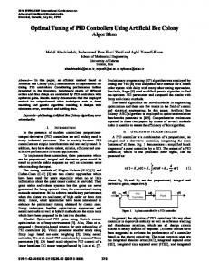
The results of the simulation show that the heuristic methods, the BFA and GA, has successfully achieved to tune the cascade PI(D) parameters of the controller, as well as the classical method. For the nominal load case the BFA achieves a system response with no overshoot, whereas the controllers designed by CM and GA achieve overshoots of 10.6 % and 2.8 %, respectively. The overshoots of the controllers designed by CM and GA are relatively high and these values may not be tolerable for applications with high precision position tracking requirements. Neither controller has steady state error. The speed and current plots show that all responses are limited in required ranges. For the zero load (unloaded) case, again the controllers designed by BFA and GA have no overshoot, whereas controller by CM yields an overshoot of 2.6 %. Neither controller has steady state error. The worst current and speed characteristic is observed at the controller by designed by CM. Once again, the BFA solution is the closest result to the targeted dynamic performance.
7. Conclusion 6. Simulation Results The previously mentioned PMDC motor is simulated for the nominally loaded and unloaded cases. In the simulations, it is aimed to simulate one full rotation of the PMDC motor, which corresponds nearly to 6.28 rad. The results are given in Fig. 8 and Fig. 9.
This study presented a comparison of different methods, which are the classical CM, BFA and GA, for tuning the PMDC motor cascade PI(D) controller parameters. For the case of the position control of a PMDC motor, it is shown that the BFA resulted in the closest solution to the desired dynamics. In the aspect of the computational convenience, the CM
Ref CM BFA GA
7 6
Position [rad]
5
4 3 2 1 0
0
0.5
1
1.5 Time [s]
2
2.5
3
2
2.5
3
2
2.5
3
(a) 40 35 30 25 Speed [rad/s]
requires some hand written pre-calculations and good insight on the plant to be controlled, so that assumptions for simplifying the problem can be made. For example, in this study the CM made assumptions that the effects of load torque, TL and back EMF Ea are neglectable. Although a stable controller for the machine parameters given in Table 1 could be achieved by CM, a successful controller design is not guaranteed for other machines, where TL and Ea can not be neglected. Moreover, the dynamics of the PMDC motor can be expressed in block diagrams which are relatively simple compared to other machines or plants. For more complex systems, hand written precalculations and assumptions may not lead to easy solutions. On the other hand, the complexity of the machine or plant is not a big issue for the BFA and GA, if a dynamic model can be implemented for the machine or plant. The only drawback of the applying the BFA and GA for more complex systems would be that the problem may require fast computers and longer computational times. It is also worth mentioning that the BFA re-
20 15 10
Ref CM BFA GA
7 6
5 0
Position [rad]
5
−5
0
0.5
1
1.5 Time [s]
4
(b)
3 12
2
10 1 8 0
0.5
1
1.5 Time [s]
2
2.5
6
3 Current [A]
0
(a)
4 2 0
30 −2 −4
25
−6 20 Speed [rad/s]
−8 15
0.5
1
1.5 Time [s]
(c)
10
5
Figure 9. Simulation results for zero load case (a) position (b) speed (c) current values.
0
−5
0
0
0.5
1
1.5 Time [s]
2
2.5
3
(b)
quired less computation time than the GA in the design example case within this study. Additionally, the heuristic methods are good options for controller tuning problems, especially for more complex systems. However, the methods may require a good starting point for converging to a solution. Moreover, when repeated, these methods usually result in slightly different solutions with similar performance parameters.
12
10
Current [A]
8
6
4
2
0
0
0.5
1
1.5 Time [s]
2
2.5
3
(c)
Figure 8. Simulation results for nominal load case (a) position (b) speed (c) current values.
In conclusion, although the heuristic methods have some disadvantages, they are very suitable options for PI(D) tuning or similar applications. Once the dynamic model of the plant is obtained, these methods can be easily implemented and solutions for very complex problems can be obtained. In this work, it is intended to design a system with critical damping ratio. As the controller designed by BFA ensured system responses with no overshoot and least settling time, it is obvious that the controller designed by BFA is the most successful one in this study.
8. References [1] A. E. Fitzgerald, Electric Machinery. 2003.
McGraw-Hill,
[2] J. J. Cathey, Electricmachines: Analysis and Design Applying MATLAB. McGraw-Hill, 2001. [3] A. F. Mergen and D. A. Kocabas¸, Elektrik Makinaları 4: Dogru Akım Makinaları. Birsen, 2006. [4] B. Niu, Y. Zhu, X. He, and X. Zeng, “Optimum design of pid controllers using only a germ of intelligence,” in Intelligent Control and Automation, 2006. WCICA 2006. The Sixth World Congress on, vol. 1, 2006, pp. 3584–3588. [5] H. O. Bansal, R. Sharma, and P. R. Shreeraman, “Pid controller tuning techniques: A review,” Journal of Control Engineering and Technology, vol. 2, no. 4, pp. 168 – 176, 2012. ˜ [6] G. A. M. Ismeal, K. Kyslan, and V. FedA¡k, “Cad of cascade controllers for dc drives using genetic algorithm methods,” Procedia Engineering, vol. 96, no. 0, pp. 182 – 189, 2014, modelling of Mechanical and Mechatronic Systems. [7] N. NithyaRani, M. GirirajKumar, and N. Anantharaman, “Modeling and control of temperature process using genetic algorithm,” International Journal of Advanced Research in Electrical, Electronics and Instrumentation Engineering, vol. 2, no. 11, pp. 5355 – 5364, 2013. [8] L. S. Patel and K. C. Dave, “Cascade control technique for d.c.motor speed control,” in Proc. of the International Conference on Science and Engineering (ICSE 2011), 2011, pp. 599 – 603. [9] Y. V. P. Kumar, A. Rajesh, S. Yugandhar, and V. Srikanth, “Cascaded pid controller design for heating furnace temperature control,” IOSR Journal of Electronics and Communication Engineering, vol. 5, no. 3, pp. 76 – 83, 2013. [10] V. Kadiyala, R. Jatoth, and S. Pothalaiah, “Evolutionary soft computing tools based tuning of pid controller for ema-afc,” in TENCON 2009 - 2009 IEEE Region 10 Conference, Jan 2009, pp. 1–6. [11] F. Aymen and S. Lassaad, “Bfo control tuning of a pmsm high speed drive,” in Electrotechnical Conference (MELECON), 2012 16th IEEE Mediterranean, March 2012, pp. 273–276. [12] B. Bhushan and M. Singh, “Adaptive control of dc motor using bacterial foraging algorithm,” Applied Soft Computing, vol. 11, no. 8, pp. 4913 – 4920, 2011. [13] Z. Chen, Y. Luo, and Y. Cai, “Optimization for pid control parameters on hydraulic servo control system based on bacterial foraging oriented by particle swarm optimization,” in Information Engineering and Computer Science, 2009. ICIECS 2009. International Conference on, Dec 2009, pp. 1–4. [14] H. Mo and Y. Yin, “Research on pid tuning of servosystem based on bacterial foraging algorithm,” in Natural Computation (ICNC), 2011 Seventh International Conference on, vol. 3, July 2011, pp. 1758–1762. [15] R.-E. Precup, A.-L. Borza, M.-B. Radac, and E. Petriu, “Bacterial foraging optimization approach to the controller tuning for automotive torque motors,” in Industrial Electronics (ISIE), 2014 IEEE 23rd International Symposium on, June 2014, pp. 972–977.
[16] N. Mohan, Electric Drives - An Integrative Approach. MNPERE, 2003.