Studies in Informatics and Control 26 (3) 277-286, September 2017
ISSN: 1220-1766 eISSN: 1841-429X
277
Tuning of Robust PID Controller with Filter for SISO System Using Evolutionary Algorithms RATHINAM Muniraj1*, MARIA SILUVAIRAJ Willjuice Iruthayarajan2, RAMAVEERAPATHIRAN Arun3 (*Corresponding author) Assistant Professor (Senior Grade), Department of EEE, National Engineering College, K.R.Nagar, Kovilpatti – 628 503, Tuticorin District, Tamil Nadu, India. e-mail:
[email protected] 2 Professor & Head of the Department, Department of EEE, National Engineering College, K.R.Nagar, Kovilpatti – 628 503, Tuticorin District, Tamil Nadu, India. e-mail:
[email protected] 3 Associate Professor, Department of EIE, National Engineering College, K.R.Nagar, Kovilpatti – 628 503, Tuticorin District, Tamil Nadu, India. e-mail:
[email protected] 1
Abstract: This paper discusses the performance comparison of Evolutionary Algorithm techniques with a view to tuning the desired design parameters of robust PID controller with filter. The design parameters of robust PID controller such as proportional gain KP, integral time constant Ti, derivative time constant Td and filter time constant td/N for Single Input Single Output (SISO) system are computed using Real coded Genetic Algorithm (RGA), Differential Evolution (DE) algorithm and Particle Swarm Optimization (PSO) algorithm. The design parameters are optimized using the statistical measures in twenty independent simulation runs. The computed design parameters obtained using Evolutionary Algorithms are used to determine the performance specifications of the Robust PID controller. The performance specifications determined are robustness with respect to model uncertainties and disturbance attenuation, set point tracking, load disturbance rejection and control energy. The test systems used to ascertain the performance specifications are Phase Locked Loop (PLL) system with motor control and Magnetic Levitation system (MLS). For PLL system, the output response obtained using the computed design parameters by RGA algorithm has proved to be better than DE and PSO. For MLS system, the output response obtained using the computed design parameters by DE algorithm has been better than PSO and RGA. Keywords: Single Input Single Output (SISO) system; Real coded Genetic Algorithm (RGA); Differential Evolution (DE); Particle Swarm Optimization (PSO).
1. Introduction Most of the industrial controllers are still designed and utilized depending on PID control algorithms. The desirable features of PID controllers are their amiability, clear functionality, applicability and ease of use. The PID controllers perform several important functions like elimination of steady state offset through integral action and anticipation of deviation and generation of corrective signals through derivative action [28]. Most of the real world problems are vulnerable to external disturbances and the robustness property of PID controller provides an efficient means of solution. Robustness of a PID controller is defined as the system’s ability to maintain its functionalities under conditions of varying internal or external parameters [9]. Minimum parameter tuning for control processes is a desirable feature of the PID controller. The three parameters to be tuned are Kp, Ki and Kd. In most cases PID controllers are used as PI controllers by switching off the derivative action. The usefulness of the robust PID controller to https://doi.org/10.24846/v26i3y201703
meet out the performance specifications of the given system mainly depends on the tuning of the controller .Since the system has nonlinear plant and various uncertainties the tuning of the robust PID controller becomes difficult. This leads to poor tuning. The reasons of the poor tuning is due to a) lack of knowledge among operators and commissioning personnel b) variety of PID structures that leads to error during tuning c) in some cases the nature of tuning method do not meet the requirement of the process involved [3]. Out of the installed PID controllers in industry, nearly one third controllers are tuned manually and remaining two third are tuned automatically. But the automatically tuned PID controllers are not effective [7].To overcome these limitations optimization algorithms are used for the tuning of robust PID controller. In the past many researchers have used different optimization algorithm for tuning the parameters of robust PID controller. But the parameter tuned to meet out the performance specifications of the system is different in each case. Many researchers have considered set ICI Bucharest © Copyright 2012-2017. All rights reserved
278
Rathinam Muniraj, Maria Siluvairaj Willjuice Iruthayarajan, Ramaveerapathiran Arun
point tracking and load disturbance rejection has the performance specifications. Few have also taken in to account the robustness against model uncertainty has performance specification of the system [18]. Amal Moharam et al in his work proposed a hybrid DE-PSO algorithm based robust PID controller [19].Jimenez et al suggested a novel method of auto tuning of PID controller using genetic algorithm [13]. Yang et al tuned the controller parameters using cuckoo search algorithm [29]. Kiam et al modelled a PID control system and tuned the parameters of the control system using intelligent control techniques [14]. Sugie et al designed a fixed structure controller with H∞ norm and tuned the deign parameters using constrained PSO algorithm [24]. Chen et al designed a PID controller structure with mixed H2 / H∞ norm and used GA algorithm to tune the design parameters for a SISO system [6]. Hultmann et al proposed a multi objective algorithm for tuning of PID controller [10]. Zhao et al tuned a robust PID controller using multi objective PSO [30]. Krohling et al designed a GA based optimal disturbance rejection PID controller for a servo motor system [16]. Kristiansson et al. proposed a structured PID controller for different plants and tuning method to find out the performance parameters [15]. Alberto Herreros et al presented a PID controller for a multi objective problem [2]. Qi Bing-Jin et al. tuned the PID controller using improved cuckoo search algorithm and observed that the overshoot and the transient time much smaller when compared to Ziegler–Nichols tuned PID controller [20]. Huang et al. suggested a robust PID controller for nonlinear system which is capable of self-tuning [25]. In this paper, Evolutionary algorithm is used to determine the optimal parameters for the robust optimal controller. Evolutionary Algorithms used are Particle Swarm Optimization (PSO), Real coded Genetic Algorithm (RGA) and Differential Evolution (DE). The main focus of this paper is to determine the design parameters of robust PID controller using evolutionary algorithm such that it meet out the system performance specifications like robustness with respect to model uncertainties and disturbance attenuation, set point tracking, load disturbance rejection and control energy. The performance of the tuned controller using evolutionary algorithm is tested on PLL and MLS system. http://www.sic.ici.ro
The main contribution in this paper is the formation of objective function by considering the robustness to model uncertainty, load disturbance rejection, set point tracking and control energy as performance specifications. Each performance specification is treated as a separate individual single objective function and a collective measure of all the performance specifications is also considered. The other noted contribution of this paper is the inclusion of a derivative filter in the robust PID controller structure. The addition of this filter alters the position of zeros in the controller such that the stability of the system is enhanced [1]. The remaining part of the paper is organized as follows: Section 2 introduces the Robust PID controller structure. Section 3 describes the formulation of objective function which meets out the performance specifications such as. Section 4 portrays the implementation of the different Evolutionary algorithms for the problem ascertained. Section 5 details about the Test system used to evaluate the performance of the tuned robust PID controller. Section 6 gives a detailed view on results and discussion. Section 7 details the inferred result of the robust controller design problem as conclusion.
2. Robust PID Controller 2.1 Structure of PID Controller A PID controller is otherwise considered as an extreme form of a phase lead-lag compensator with one pole at the origin and the other at infinity. A standard PID controller is also known as three term controller. The transfer function for standard PID controller is parallel form is given by
G(s) = K p + K I
1 + KDs s
(1)
In Ideal form it is given by
1 G ( s ) = K p 1 + + Td s Ti s where
Kp
= Proportional gain,
K I = Integral gain, K D = Derivative gain,
(2)
Tuning of Robust PID Controller with Filter for SISO System Using Evolutionary Algorithms 279
where the closed loop system is also asymptotically
Ti = Integral time constant,
stable with ∆P (s ) and d (t ) , where W1 ( s ) is a stable weighting function matrix specified
Td = Derivative time constant. The ‘‘three term” of a PID controller are highlighted below [5]:
by the designers. S (s ) and T ( s ) = 1 − S ( s ) are the sensitivity and complementary sensitivity functions of the system respectively.
--
S ( s ) = (1 + P( s )Gc ( s ) )
The proportional term – providing an overall control action proportional to the error signal through the all pass gain factor.
--
The integral term – reducing steady state errors through low frequency compensation by an integrator.
--
The derivative term – improving transient response through high frequency compensation by a differentiator.
2.2 Structure of Robust PID Controller Consider a control system with ni inputs and no outputs as shown in Figure 1, where P(s ) is the plant transfer function, ∆P(s ) is the change in plant,
Gc (s ) is the controller transfer function , r (t ) is the reference input signal, u (t ) is the control input, e(t ) is the error signal, d (t ) is the external disturbance and y (t ) is the output of the system [17].
−1
(6)
T ( s ) = P( s )Gc ( s ) (1 + P( s )Gc ( s ) )
−1
(7)
H ∞ norm in (3) and (4) is defined as
A(s ) = aX ω σ ( A( j ω )) ∞
(8)
2.3 Control structure of Robust PID controller with filter The transfer function of Robust PID controller with filter is given as
T s 1 d + K ( s ) = K p 1 + Ti s 1 + t d s N
(9)
where
Ti = Integral time constant Td = Derivative time constant td
Figure 1. Control system with plant perturbation and external disturbance
The change in plant or plant perturbation is bounded by a known stable function matrix W1 ( s ) .
σ (∆P( jω ) ) ≤ σ (W1 ( jω ) ), Vω (0, ∞) ,
(3)
where σ ( A) denotes the maximum singular value of a matrix A. The controller Gc (s) is designed by considering an asymptotically stable nominal feedback control system (ΔP(S) = 0 and d(t) = 0) is, the robust stability performance satisfies the following inequality
W1 ( s ) S ( s ) ∞ < 1
(4)
W2 ( s )T ( s ) ∞ < 1
(5)
N
= Filter time constant
Mostly in PID controllers the derivative part is switched off since the tuning of the controller in the derivative section is difficult. Also the inherent amplification of the measurement noise if not filtered properly can cause damage to the actuator. Therefore there is a need to connect a derivative filter in the Robust PID controller design. The zeros of the PID controller without derivative filter are determined by solving equation 10. The zeros obtained are given by equation 11. The zeros of the PID controller with derivative filter are determined by solving equation 12. The zeros obtained are given by equation 13.
TiTd S 2 + Ti ( s ) + 1 = 0
(10)
The zeros are Z1, 2
1 2 − Ti Ti − 4TiTd = 2 TiTd
(11)
ICI Bucharest © Copyright 2012-2017. All rights reserved
Rathinam Muniraj, Maria Siluvairaj Willjuice Iruthayarajan, Ramaveerapathiran Arun
280
If the derivative filter is applied, the zeros of the controller are the solution of the equation.
3.2 Set point tracking
The usage of the filter along with the robust PID Controller significantly enhance the load disturbance rejection performance with a modest increase of a control energy i.e., addition of the filter reduces the control energy for increase in load disturbance rejection [8].
Set point tracking is expressed in terms of the integral performance index J2 for a step change in set point that always a large initial error. These initial errors are weighted to give a stable output response. Here, the error is defined as the difference between the PV and a user-defined first order reference trajectory yr (t) connecting the actual PV and the set point. By specifying the time constant of the trajectory, the user can affect the speed of the response to set point changes. The relative importance of each specification depends on the specific control application. Set point changes are more important in other applications such as motion control systems [21].
3. Problem Formulation
J 2 = ∫ y (t ) − r (t ) dt
T 1 TiTd 1 + S 2 + Ti + d N N
S + 1 = 0
(12)
The zeros are Z 1, 2
1 2 − Ti N − Td ± (Ti N − Td ) − 4Ti Td N 2 2 = Ti Td (1 + N )
(13)
∞
The problem formulation involves the tuning of the design parameters of robust PID controller to meet out the desired performance specifications. In this paper, the tuning of a robust PID controller has taken into account the following performance specifications such as robustness with respect to model uncertainties and disturbance attenuation, set point tracking, load disturbance rejection and control energy. These specifications are analysed and characterized in terms of norms of signals and systems. The improvement of these performance specifications is formulated as a single objective problem with mixed H2 and H∞ norm.
3.1 Robustness with respect to model uncertainties and disturbance attenuation This is a crucial objective in the design of robust PID controller. Conventional methods like Ziegler Nichols and Cohen - Coon methods failed to produce robust controller designs with guaranteed robustness degree. Hence stability of the control system gets affected [31]. Minimize J1 = (J + Jb ) 2 a
2 1/2
(14)
where J1 = robustness with respect to model uncertainties and disturbance attenuation Ja = model uncertainty in H ∞ norm Jb = disturbance attenuation in H ∞ norm
J1 =
W1 ( s ) S ( s )
∞
+ W2 ( s )T ( s )
∞
1 2
(15)
subjected to the constraints in eqns. (4) and (5). http://www.sic.ici.ro
0
(16)
where y (t ) = output process variable
r (t ) = reference input
3.3 Load disturbance Rejection In process control the important performance specification required for a PID controller is load disturbance rejection. It is expressed in terms of J3 It is an integral performance measure of the output to unit step disturbance input when any other input is zero. There are no detailed assumptions made about the load disturbances except that they are low frequency [27]. ∞
J 3 = ∫ w(t ) − y (t ) dt 0
(17)
where y (t ) = output process variable
w(t ) = unit step disturbance
3.4 Measurement of control energy The fourth performance measure determined by Robust PID controller is control energy (J4) . It is energy required for the disturbance to settle down [27]. To evaluate control energy, compute the Total Variation (TV) of the input U(t), which is sum of all its moves up and down.
TV = U ( k + 1) − U (k )
(18)
The Total Variation is a good measure of the smoothness of the signal and it should be
281 Tuning of Robust PID Controller with Filter for SISO System Using Evolutionary Algorithms
small. A control system exhibits high degree of performance if it provides rapid and smooth response to input changes. The control energy is computed as the total variation of set point tracking and load disturbance rejection.
3.5 Objective function In this paper, the performance specifications are treated as individual objective functions J1, J2, J3 and J4. These objective functions are treated as minimization function. The output response of the designed robust PID controller is obtained by the summation of individual functions J1, J2, J3 and J4. Hence the objective function of the problem under study has been formulated as Minimize Jall = {J1 + J 2 + J 3 + J 4 } ,
(19)
where J1 = Robustness with respect to model uncertainties and disturbance attenuation
J 2 = Set point tracking
J 3 = load disturbance rejection J 4 = control energy
Jall = Performance of Robust PID controller PID controller with equal weightage.(i.e. J1, J2, J3 and J4 have equal weightage as 0.25).
4. Tuning of design parameters of robust PID controller using Evolutionary Algorithms Evolutionary algorithms are now widely used by the researchers to tune the robust PID controller to meet out the desired performance specifications of the system used. These algorithms are better than traditional analytical methods, since these algorithms make use of population of solutions and not a single point solution. Evolutionary algorithms search for the optimum solution in the search space and hence it has least possibility to converge into local optima. Many evolutionary algorithms have different methodologies to weed out poor off springs and generate fittest population. For solving global functional optimization problems, algorithms like RGA, PSO and DE have been developed. Using these algorithms the convergence rate of obtaining global optimum solution is increased. In this paper RGA, DE and PSO algorithms are used to find out the design parameters of robust PID controller with filter.
4.1 Real coded Genetic Algorithm with SBX crossover Genetic Algorithm (GA) was introduced by John Henry Holland in the early 1970’s. GA is inherently parallel, because it simultaneously evaluates many points in the parameter space and thus has reduced the probability of getting trapped in to local optimum. Real-number encoding is superior for optimization problems with respect to other binary, and grey coded GAs. GA helps to converge to the global optimum [26] with five components. Step 1: Representation of solutions according to the optimization problem. Step 2: Initialisation of population of solutions. Step 3: Evaluation of solution based on the fitness. Step 4: Select parents using Tournament selection for taking up reproduction. Step 5: Generate offspring using genetic operators (SBX crossover and polynomial mutation operators) by altering the genetic composition of children during reproduction. They are explained as under.
4.1.1 Simulated Binary crossover In SBX crossover, two offspring solutions are generated from two parents. Choose a random number uu i ε 0;1 and calculate βqi as given below: 1 ηc +1 , 2 uu uu i ≤ 0.5 ( ) i 1 ηc +1 βqi = 1 , otherwise 2(1 − uu i )
(20)
where βqi is spread factor and ηc is the crossover index. Then compute the children,
Xi
2 , g +1
Xi
1, g +1
and
using
(2,g ) ( 1 , g +1 ) (1 , g ) Xi = 0.5 1 + βqi X i + 1 − βqi X i (2,g ) ( 2 , g +1 ) (1 , g ) = 0.5 1 − βqi X i + 1 + βqi X i Xi
(
(
)
)
(
(
)
)
(21)
ICI Bucharest © Copyright 2012-2017. All rights reserved
Rathinam Muniraj, Maria Siluvairaj Willjuice Iruthayarajan, Ramaveerapathiran Arun
282
4.1.2 Polynomial Mutation
Two multipliers c1 and c2
Offspring thus generated from crossover needs to undergo polynomial mutation operation. Like in the SBX operator, the probability distribution is a polynomial function, rather than a normal distribution. The new offspring is given as
Subroutine: PSO update
y
(1,t +1) i
=x
(1,t +1) i
(
)
+ x − x δi U i
L i
(22)
)
ri < 0.5 ri ≥ 0.5
(23)
where, xiU and xiL are the upper and lower limit values; and ηm is the mutation index. Step 6: Generate new population with replacement mechanism, wherein 80% of the fitter off springs and 20% of the best initial population become the individuals for the next generation. Procedure gets repeated until the stopping criterion is satisfied.
4.2 Particle Swarm Optimization (PSO) PSO is a population-based search procedure in which individuals called particles fly and change their positions in a multidimensional search space with respect to time. During flight, each particle adjusts its position based on its own learning and the experience of neighbouring individuals, thus make use of the best location encountered by own self and its neighbours [12]. The swarm direction of a particle is defined by the set of individuals neighbouring the particle and its experience history. The PSO algorithm requires the parameters followed below: Maximum and minimum velocity that limit vi (t ) within the range [Vmin, Vmax] An inertial weight wt, and maximum number of iterations Two random numbers r1 and r2 which decide the influence of pi (t ) and g i (t ) on the velocity updating http://www.sic.ici.ro
for all particles do Perform fitness evaluation Calculate pi by identifying the best position of ith individual at iteration kth and gi by finding the best position of the group until iteration ‘k’.
nm
1 ( nm + 1 ) − 1, if ( 2ri ) 1 ( nm + 1 ) δ i = 1 − 2 (1 − ri ) , if
while stopping condition is not met do
Set iteration count, say, ‘k’
where, factor ‘ δ i ’ is found using
P(δ ) = 0.5(n m +1)(1 − δ
Initialize randomly particle’s position and velocity xi(0) and vi(0)
Update the velocity using v i (t + 1) = wv i (t ) + c 1r1 ( pi (t ) − x i (t )) + c 2r2 ( g i (t ) − x i (t ))
(24)
Calculate the movement of the swarm by updating the position of the particle using
xi (t + 1) = xi (t ) + vi (t + 1)
(25)
since each individual moves from the current position to the next one with the modified velocity end for Check with the maximum iteration count and if not satisfied, increase the iteration count and repeat the procedure from Step 3. end while Return: Optimum attractiveness
4.3 Differential Evolution DE is an efficient population-based stochastic search technique for global optimization in many real problems. Differential Evolution is developed from Ken Price’s attempts to find out solution for Chebychev Polynomial fitting Problem [23]. When Ken got an idea of using vector differences for perturbing the vector population, a breakthrough has come up. DE is considered better, since random direction is generated by simple vector subtraction and more variation in population leads to more search over solution space. Step 1: Generate the initial population ( Np ) by
{
}
X i ,G = xi1,G ,...., xin,G , where i = 1, 2,Np
(26)
Tuning of Robust PID Controller with Filter for SISO System Using Evolutionary Algorithms 283
n = Dimension, which is chosen randomly and must bound the complete parameter space constrained by the specified minimum and maximum limits. Step 2: Mutation Operation At each generation, after initialization DE uses mutation to produce a mutant vector, Vi G for each target vector, X i G . The mutant vector can be produced by several mutation strategies. The basic mutation operation is given as
Vi = X r1 + F .( X r 2 − X r 3 )
(27)
where, r1 , r2 , r3 are three random indexes between
i = 1, 2,Np , excluding, ‘i’; F is a scaling factor. Step 3: Crossover operation Crossover operation is applied to each pair of the target vector X i G and its corresponding mutant vector Vi G to generate a trial vector, U i G DE generally employs the binomial crossover defined by u
j i ,G
v ij,G , j = x i ,G ,
if (rand j 0, 1) ≤ CR or (j = j rand ) otherwise
(28)
where f (U i ,G ) is the fitness function value of the ith trial vector; and f ( X i ,G ) is the fitness function value of the ith target vector. The loss of the superior individuals in the subsequent iteration is prevented by the selection process, since the fitter individuals replace the inferior individuals. This process continues until the maximum function evaluations or generations are reached.
5. Test Systems In order to validate the performance of the robust PID controller with filter, two SISO test systems are considered.
5.1 Test System 1 The transfer function of the test system 1 i.e., phase locked loop motor speed control system [4] is given as
P (s ) =
68.76 S (1 + 0.05s )
Also the system suffers from an external disturbance d(t) = 0.1 e -0.1t sin (0.8πt) and the plant perturbation transfer function is given as
∆P ( s ) =
j = 1, 2,...., n
The crossover rate is a user-specified constant within the range [0,1), which controls the fraction of parameter values copied from the mutant vector. jrand is a randomly chosen integer in the range [1,n]. The condition j = jrand is introduced to make sure that the trial vector will vary from its corresponding target vector by at least one parameter. Otherwise, new parent vector would not be generated and the population will not vary. Step 4: Selection A selection phase is necessary to decide, if the trial vector enters the next generation population or not. In the selection phase each trial vector is compared to the corresponding target vector and the better vector will come into the population of the next generation. ,
(29)
(30)
0.6 s + 0.2s + 8
(31)
2
The plant perturbation transfer function is bounded between two weighting function namely
W1 ( s ) and W2 ( s )
W1 ( s ) =
0.6 s + 0.2s + 8
(32)
2
0.5s + 0.05 (33) s + 0.2s + 6.3265 The controller transfer function is given by
W 2 (s ) =
2
Td s 1 K (s) = K p 1 + + Ts T i 1 + d s N 5.2 Test System 2
(34)
Consider the Magnetic Levitation system as test system 2 [11,22] and its linearized model about an equilibrium point of y = 0.018 is given as P (s ) =
7.147 s s 22 55 − . ( ) ( + 20.9) (s + 13.99)
(35)
ICI Bucharest © Copyright 2012-2017. All rights reserved
Rathinam Muniraj, Maria Siluvairaj Willjuice Iruthayarajan, Ramaveerapathiran Arun
284
The PID controller transfer function is given by x 1 10 2 s x K (s ; x ) = 10 1 1 + x + 10 2 s 1 + 10( x 3 − x 4 ) s
(36)
where X = ( x1 , x2 , x3 , x4 ) denotes the design parameter vector. T
Suppose the initial search space of the design parameter vector is given by
D := {x ∈ R
4
T T | (2,−1,−1,2) ≤ x ≤ (4,1,1,3) }
(37)
The design parameter x which satisfies the following multiple H ∞ constraints given in eqns. (4) and (5) are determined. The plant perturbation is unknown in fact, but bounded by the following known stable function.
W 1( s ) = 5 (s + 0.1)
Table 1. Design Parameters obtained for PLL system using different optimization algorithms S1 Algorithm No 1. 2. 3.
RGA DE PSO
Design parameters KP 0.1196 0.1464 0.1152
Ti 0.3405 0.5723 0.3273
Td 0.6559 0.4733 0.6736
td/N 4.8694 3.8388 4.9647
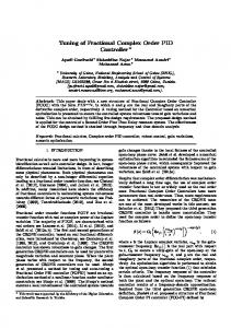
The convergence characteristics obtained using PSO, DE and RGA is shown in Figure 2. From the convergence characteristics it is clear that RGA converges faster than PSO and DE.
(38)
W2(s ) = 4.3867 × 10⁻⁷ ( s + 0.066 ) ( s + 31.4 ) s 88 + ( ) 104 s + 104
(
3
)
(39)
6. Simulation Results The performance of the proposed evolutionary algorithm tuned Robust PID controller is validated using two different test systems. The two different test systems used are phase locked loop motor speed control system and simple magnetic levitation system. The evolutionary algorithms used for the determination of best design parameters are RGA, DE and PSO. The coding is run using MATLAB 7.10.0 software on Pentium 4 PC 2.16 GHZ with 2 GB RAM. Since the solutions obtained using evolutionary algorithm is probabilistic in nature, many trials with independent population initializations are used to check the constant performance of algorithms. As the number of design parameters is four, the population size is fixed as 40. In this work 20 trials are conducted and feval max is fixed as 4000. 6.1 Simulation results for Test System 1 The design parameters like proportional gain KP, integral time constant Ti, derivative time constant Td and filter time constant td/N obtained for the PLL motor speed control system using RGA, PSO and DE are given in Table 1. http://www.sic.ici.ro
Figure 2. Convergence characteristics for PLL system
The overall response (Jall) of the system with plant perturbation ΔP(s) and the performance specification parameters like robustness with respect to model uncertainties (J1), set point tracking (J2), load disturbance rejection (J3) and control energy (J4) using DE, PSO and RGA tuned controller is shown in Table 2. Table 2. Performance parameter specifications of robust PID controller obtained using RGA, DE and PSO for PLL System
The output response of the PLL system obtained using the design parameters computed by RGA, DE and PSO is shown in Figure 3.
Figure 3. Output response of PLL system
Tuning of Robust PID Controller with Filter for SISO System Using Evolutionary Algorithms 285
From the overall (Jall) value and the output response, it is clear that RGA algorithm is better than DE and PSO to meet out the system specifications i.e., RGA tuned robust PID controller performs better with plant perturbation and model uncertainties for PLL system.
6.2 Simulation results for Test System 2 The design parameters like proportional gain KP, integral time constant Ti, derivative time constant Td and filter time constant td/N obtained for the magnetic levitation system using RGA, PSO and DE are given in Table 3. Table 3. Design Parameters obtained for MLS system using different optimization algorithms Design parameters
Sl No
Algorithm
Ti
Td
td/N
1.
RGA
3.2452
-0.9991
-0.7023
2.2815
2.
PSO
3.2467
-1.000
-0.7047
2.2771
3.
DE
3.2477
-0.9764
-0.7155
2.4099
KP
The overall response (Jall) of the system with plant perturbation ΔP(s) and the performance specification parameters like robustness with respect to model uncertainties (J1), set point tracking (J2), load disturbance rejection (J3) and control energy (J4) using DE, PSO and RGA tuned controller is shown in Table 5. Table 5. Performance parameter specifications of robust PID controller obtained using RGA, DE and PSO for MLS System S1 No
Algorithm J1
J2
J3
J4
Jall
1.
RGA
1.3428
0.3518
0.000205
10.8478
12.5426
2.
PSO
1.3401
0.3552
0.000208
11.0520
12.7475
3.
DE
1.5270
0.3429
0.000211
10.0615
11.9316
The output response of the MLS system using the design parameters computed by RGA, DE and PSO is shown in Figure 5.
The convergence characteristics obtained using RGA, PSO and DE is shown in Figure 4. From the convergence characteristics it is clear that DE has the lowest fitness characteristics than RGA and PSO.
Figure 5. Output response of MLS system
From the overall (Jall) value and the output response, it is clear that DE algorithm is better than RGA and PSO to meet out the system specifications i.e., DE tuned robust PID controller performs better with plant perturbation and model uncertainties for MLS system.
7. Conclusion Figure 4. Convergence characteristics for MLS system
In Magnetic Levitation System the PID controller structure is given by eqn. (36), where x=(x1, x2, x3, x4)T denotes the design parameter vector. Here Kp=10x1, Ti=10x2, Td=10x3 and td/N=10(x3-x4). The modified transfer function obtained by substituting the computed design parameters using RGA, PSO and DE for robust PID controller with filter is given in Table 4. Table 4. Modified Transfer function obtained for robust PID controller with filter using RGA, PSO and DE S 1 Algorithm Transfer function of robust PID with filter No obtained using the design parameters 1.
RGA
K(s)=1758.7*(1+(1/0.1002s)+(0.1985s/ (1+(1/0380*10-3)s))
2.
PSO
K(s)=1764.8*(1+(1/0.1s)+(0.1973s/ (1+(1.0427*10-3)s))
3.
DE
K(s)=1768.9*(1+(1/0.1056s)+(0.1925s/ (1+(0.7492*10-3)s))
The performance comparison of Evolutionary Algorithm techniques to tune the desired design parameters of robust PID controller with filter is discussed in this paper. The design parameters of robust PID controller with filter structure for Single Input Single Output (SISO) system is computed using Real coded Genetic Algorithm (RGA), Differential Evolution (DE) algorithm and Particle Swarm Optimization (PSO) algorithm. Simulation results show that the overall performance of the robust PID controller obtained by the computed design parameters using RGA is better than PSO and DE for PLL system and for MLS system DE tuned robust PID controller performance is better than RGA and PSO.
REFERENCES 1. Aidan O Dwyer, (2006), Handbook of PI and
PID controller tuning rules, Imperial College Press, London. 2. Alberto Herreros, Enrique Baeyens, & Jose R. Peran, (2002), Design of PID – Type controllers ICI Bucharest © Copyright 2012-2017. All rights reserved
286
Rathinam Muniraj, Maria Siluvairaj Willjuice Iruthayarajan, Ramaveerapathiran Arun
using Multi objective GA, ISA Transactions, 41, pp. 457-472. 3. Astrom, K. & Hagglund, T. (1995), PID Controllers: Theory, Design, and Tuning, 2nd Edition. Instrument Society of America, Research Triangle Park, NC. 4. Bor – Sen Chen & Yu – Min Cheng, (1998), A structure – specified H∞ Optimal control design for practical applications: A genetic approach, IEEE Transactions on Control Systems Technology, 6(6). 5. Cheng-Ching yu, (2006), Auto Tuning of PID controllers – A relay feedback approach, Springer, 2nd Edition. 6. Chen, Yu Min Cheng, & Ching Hsiang Lee, (Oct.1995), A Genetic Approach to mixed H2/ H∞ optimal PID control, IEEE control systems, pp. 51-59. 7. Coelho, L.S. & Pessôa, M.W. (2011), A tuning strategy for multivariable PI and PID controllers using differential evolution combined with chaotic Zaslavskii map”, Expert Systems with Applications, 38(11),13694–13701. 8. Ding yu Xue, Yang Quan-Chen, Derek, P. & Atherton, (2002), Linear feedback control – Analysis and Design with MATLAB, Springer Verlag. 9. Felix, M.A. & Wagner, A. (2008), Robustness and evolution: Concepts, insights and challenges from a developmental model system, Heredity, 100(2), 132–140. 10. Helonvicente Hultmann, Ayala & Leandro dos Santos Coelho, (Aug.2012), Tuning of PID controller based on a multi objective genetic algorithm applied to a robotic manipulator, Expert systems with applications, 39(10), 8968 – 8974. 11. Ichiro Maruta,Tae Hyoung Kim,Toshiharu (2009), Fixed-structure H∞ controller synthesis: A meta-heuristic approach using simple constrained particle swarm optimization, Automatica 45, 53-559. 12. James Kennedy & Russell Eberhart (1995), Particle Swarm Optimization, Proceedings of International Conference on Neural Networks, Perth, Australia. 13. Jimenez, (Dec.2015), An auto-tuning PID control system based on genetic algorithms to provide delay guarantees in Passive Optical Networks, Expert Systems with Applications, 42(23), 9211-9220. 14. Kiam Heon Ang, G. & Chong, Yun Li, (2005), PID control system analysis, design and technology, Published in IEEE Transactions on Control Systems Technology, 13( 4), pp. 559 – 576. 15. Kristiansson, B. Lennartson, (2002) “Robust and optimal tuning of PI and PID controllers”, Proceedings in IEEE Control Theory Applications, vol. 149, no. 1, pp. 17-25. 16. Krohling, (1997), Design of PID controller for disturbance rejection: A genetic Optimization approach, 2nd International Conference on Genetic Algorithms in Engineering Systems, pp. 498-503. 17. Ming Hao Hung, Li Shun Shu, Shinn Jang Ho, Shiow Fen Hwang & Shinn Ying Ho, (Mar.2008), A Novel Intelligent Multi objective Simulated Annealing for designing robust PID controllers, http://www.sic.ici.ro
IEEE Transactions on Systems, MAN and Cybernetics –Part A, Systems and Humans, 38(2). 18. Moharam Mostafa A. El-Hosseini & Hesham A. Ali, (2015), Design of optimal PID controller using NSGA II Algorithm and Level Diagram, Studies in Informatics and Control, 24(3), 301-308. 19. Moharam,Mostafa A.EI- Hosseini, Hesham A. Ali,(2016),Design of optimal PID controller using hybrid differential evolution and particle swarm optimization with an aging leader and challangers”,Appied Soft Computing, 38(C), 727-737. 20. Qi Bing–Jin, Lin Feng–Qi, Beiyan–Jiang & Qi– Wang, (2014), Novel improved Cuckoo search for PID controller Design, Transactions of the Institute of Measurement and control, 37(6), 721-731. 21. Rainer Dittmar, A. Shabroz Gill, Harpreet Singh & Mark–Darby, (2012), Robust Optimization – Based Multi-loop PID controller tuning: A new tool and its industrial application, Control Engineering Practice, 20, 355-370. 22. Sreepriya, S. Baskar S. & Willjuice Iruthayarajan M. (2010), Covariance matrix adopted evolutionary strategy based design of robust optimal fixed structure controller, Proceedings of Second International Conference on Computing, Communication and Networking Technologies. 23. Storn, R. & Price, K. (1997), Differential Evolution - A simple and efficient heuristic for global optimization over continuous spaces, Journal of Global optimization, 11(4), 341-359. 24. Tae-Hyoung Kim, Ichiro Maruta, & Toshiharu Sugie (2007), Robust PID controller tuning based on the constrained Particle Swarm optimization, Automatica, 44(4), 1104-1110. 25. Tan, K. K. Huang, S. & Ferdous, R. (2002), Robust self-tuning PID controller for non linear systems, Journal of process control, 12(7), 753-761. 26. Thomas Back & Hans-paul schwefel, (1993), An overview of Evolutionary Algorithms for parameter optimization, Evolutionary computation, 1(1), 1-23. 27. Vijayakumar, V. Rao, V.S.R. & Chidambaram, M. (2012), Centralized PI controllers for interacting multi variable processes, ISA Transactions, 51, 400-409. 28. Wang, L. Barnes, T.J.D. & Cluett, W.R. (1995), New frequency-domain design method for PID controllers,” Proceedings of Institute of Electrical Engineers in Control Theory Applications, 142(4), pp. 265–271. 29. Yang, X.S. & Deb, S. (2010), Engineering optimisation by cuckoo search, International Journal of Mathematical Modeling and Numerical Optimisation, 1(4), 330–343. 30. Zhao, Y. & Liu, H.L. (2013), Multiobjective particle swarm optimization based on population decomposition, Lecture Notes in Computer Science, 8206, Springer, Berlin, Heidelberg. 31. Zhao, S. Z. Willjuice Iruthayarajan, M. S. Baskar, S. & Suganthan, P.N (2011), Multi- Objective Robust PID controller tuning using Two Lbests Multi – objective Particle Swarm Optimization”, Information sciences, 181, 3323-3335.