UML collaboration diagram syntax: an empirical study of comprehension Helen C. Purchase*, Linda Colpoys†, Matthew McGill† and David Carrington† *Department of Computing Science, University of Glasgow † School of Information Technology and Electrical Engineering, University of Queensland
[email protected],
[email protected]
Abstract The UML syntactic notation used in texts, papers, documentation and CASE tools is often different, despite UML being considered a software engineering standard. Our initial empirical study considered variations in the notation used for UML class diagrams; the experiment reported here concentrates on UML collaboration diagrams. The decision as to which of the semantically equivalent notational variations within the UML standard to use appears to be according to the personal preference of the author or publisher, rather than based on any consideration of the ease with which the notation can be understood by human readers. This paper reports on an experiment that takes a human comprehension perspective on UML collaboration diagrams. Five notations were considered: for each, two semantically equivalent (yet syntactically or stylistically different), variations were chosen from published texts. Our experiment required subjects to indicate whether a supplied pseudo-code specification matched each of a set of experimental UML collaboration diagrams. The results reveal that our informal, personal intuitions (which were based on our view of the complexity of the notation) are validated with respect to confirming that a specification matches a diagram, but not when errors in a diagram are to be identified. The subjects' preferences are in favour of the more concise notational variants.
1. Introduction In recent years, the Unified Modelling Language (UML) has emerged as the defacto standard for the representation of software engineering diagrams [15]. While adopted as a standard by the membership of the OMG (Object Management Group) in 1997 [15], a glance through different texts that use UML, or an
investigation of current CASE tools, reveals a number of notational variations [2, 4, 9, 10]. As a standard, UML is still evolving, and within each version of the standard are many semantically equivalent notational variations from which authors or publishers may choose, according to their personal preference. There seems to be no basis for the choice of one notational variation over another. It may be that one notational variation is easier to comprehend than another. Our previous study [14] investigated notational variants of UML class diagrams, and found that the best performing notation may depend on the task for which it is used, and that our personal, intuitive predictions were partly confirmed. This study considers various notations for UML collaboration diagrams in a similar manner, and aims to determine which notational variants are easier for humans to understand. The research reported in this paper attempts to determine whether there are any comprehension differences between five notational variations for UML collaboration diagrams, through an empirical study of subjects' performance on a specification matching task. The notational variants may be equally as good as each other, in which case, it does not matter which one is used. But, if there are comprehension differences, the results of this study could assist in the definition of appropriate notational standards (from a human understanding point of view), and in determining the most suitable notation to use in UML texts, CASE tools, and practical software engineering tasks. Some theoretical analytical work has been performed on software engineering notations and visual programming languages, but no empirical studies on human comprehension of these notations have been found. While software engineering notations (including UML) have been analysed and compared using the Cognitive Dimensions framework [1, 5], this framework is theoretical, and these analyses, while providing interesting structured perspectives on the notational features, are not based on experimental data [3, 6, 7, 8]. The experiment reported here complements such analytical work.
Proceedings of the First International Workshop on Visualizing Software for Understanding and Analysis (VISSOFT’02) 0-7695-1662-9/02 $17.00 © 2002 IEEE
5: displayAge(i)
showAge(name:String)
2: s:=getStudent(name)
1: showAge(name) ui:UI
User
sys:System
los:ListOfStudents
3: getName()
4: i:=getAge()
s:Student
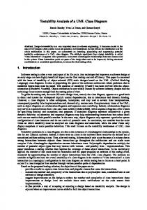
Figure 1. Example of a UML collaboration diagram. •
1.1. Experimental aim and definitions Our previous study [12] considered user preferences for some UML class and collaboration notations and layout features. This experiment concentrates on user performance, rather than preference, and focuses on collaboration diagrams. We identified two syntactically different ways of representing each of five different semantic constructs in UML collaboration diagrams. The aim of this experiment was to determine which of the two variants of each of these five notations is more suitable with respect to human performance. By asking subjects to perform comprehension tasks on a number of semantically equivalent UML collaboration diagrams that vary with respect to the notations used, we aimed to identify the notational variants that resulted in the best performance. UML collaboration diagrams describe the interactive view of a UML class diagram [15], detailing the objects and interactions of the software system. UML collaboration diagrams demonstrate how objects in the system interact with each other, and the order in which interactions occur by way of message passing. Figure 1 is an example of a small UML collaboration diagram, showing the interactions between the objects in a simple system that finds and displays the age of a student, whose name is entered by the user.
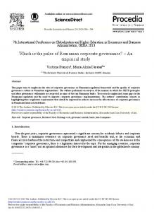
1.2. Notational variations Five independent notational variations for UML collaboration diagrams were considered (see Figure 2): each notation (N1, N2, N3, N4, N5) has two variations (a) and (b), with identical semantics. • N1(a) and N1(b) represent the syntax of two different notational variants for numbering messages.
• • •
N2(a) and N2(b) represent the syntax of two different notational variants for depicting message arrows. N3(a) and N3(b) represent the syntax of two different notational variants for depicting selfmessages. N4(a) and N4(b) represent the syntax of two different notational variants for associating message labels with arrows. N5(a) and N5(b) represent the syntax of a further two different notational variants for associating message labels with arrows.
All notational variations had been found in published UML documents, except N5(b), which was used in a prior experiment which considered user preference of notational variations [12]. Our informal predictions, based purely on our personal intuition and experience, and on informal discussions with colleagues, were that the (a) notations would produce better performance, as we considered them to be more concise.
2. Experimental task The comprehension task was to match a given textual code description against a set of diagrams, indicating whether each diagram correctly matches the description or not. The set of diagrams included both correct and incorrect diagrams.
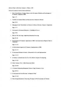
2.1. Experimental materials 2.1.1. The application domain The collaboration diagram used was based on a simple domain, which models a preferential voting system, in which the voter must rank the candidates in order of preference. The example includes an actor, 7 objects, 11 links and 13 messages (see Figure 3). It would be infeasible to use large diagrams in a
Proceedings of the First International Workshop on Visualizing Software for Understanding and Analysis (VISSOFT’02) 0-7695-1662-9/02 $17.00 © 2002 IEEE
Notational Difference
Variation (a)
Variation (b)
1: message1() a:Class1
Message numbering: whole or partial (N1)
1: message1() b:Class2
a:Class1
b:Class2
1.1: message2()
2: message2 2: message3()
3: message3()
c:Class3
c:Class3
(Larman, 1998)
(Fowler, 2000) 1: message1()
1: message1()
Arrows associated with messages: placement and size(N2)
a:Class1
a:Class1
b:Class2
b:Class2
2: message2() 2: message2
3: message3()
3: message3() c:Class3 c:Class3
(Booch et al., 1999)
(Larman, 1998)
1: message1() 1: message1() a:Class1
a:Class1
(Page-Jones, 2000)
(Maciaszek, 2001) 1: message1()
Broken arrows, placement of message text (N4)
a:Class1
self:Class1
1: message1()
b:Class2
a:Class1
b:Class2
2: message2()
2: message 3: message3()
3: message3()
c:Class3
c:Class3
(Maciaszek, 2001)
(Fowler, 2000)
1: message1()
1: message1()
Message adjacency, horizontal or vertical placement of text (N5)
a:Class1
b:Class2
a:Class1
3:
2: message2 3: message3()
me ss ag e3 ()
c:Class3
c:Class3
(Booch et al., 1999)
b:Class2 2: message2()
Representation of selfmessages (N3)
(Purchase et al, 2000)
Figure 2. The five notational variations. comprehension task like that used in this experiment, as a large domain would take too long for the subjects to read and comprehend. In addition, the modularity principle encourages designers to partition large diagrams into multiple smaller ones, so the size of the application used in this study is realistic A textual code description of this application domain was produced in pseudo code, along with a short description of the system being modelled. The subjects were asked to match the experimental diagrams against this specification. 2.1.2. UML tutorial and worked example A tutorial sheet explained the meaning of UML collaboration diagrams, and, using a simple example, described the semantics of all the notational variations.
While the subjects had some prior knowledge of UML as part of their studies, this tutorial provided all the UML background information they required for the experimental task, and was intended to ensure that all subjects had a consistent base of UML knowledge. A worked example demonstrated the task that the subjects were to perform, by presenting a small specification with four different diagrams, and for each diagram indicating whether it matched the given specification or not. Where the diagram did not match the specification, the errors were explained. Care was taken to ensure that neither the tutorial nor the worked example would bias the subjects towards one notational variation over another by using all notational variations equivalently.
Proceedings of the First International Workshop on Visualizing Software for Understanding and Analysis (VISSOFT’02) 0-7695-1662-9/02 $17.00 © 2002 IEEE
startCount() ui:UI
Moderator
12: dropLowest() [there's no clear winner]
1: startCount()
5: dropLowest() [there's no clear winner] sys:System
2: assignVotes()
cs:CandidateSet
7: dropped(c) [c has the smallest number of votes]
6: i:=getCount() 9: reassignVotes()
4: add(v) vs:VoteSet
3: c:=getFirstPref()
c:Candidate
10: d:=getNextPref()
11: add(v)
8: remove(c)
v:Vote
d:Candidate
Figure 3. The application domain for the experiment.
2.2. The experimental diagrams The UML diagram representing the experimental domain was drawn four times, in four differing layouts. Each layout was constructed with a view to minimising the potential for any confounding layout factors. Thus, each layout had no edge bends, a similar number of sloping lines, no edge crosses, comparable orthogonality (the property of fixing nodes and edges to the intersections and lines of an invisible unit grid), and was of a similar size. Different layouts were required so that the subjects would not merely use visual pattern matching in performing the comprehension tasks: if all the diagrams had identical layout, the differences between them would be visually obvious and detectable without the subject needing to understand the information embodied in the diagram. Using these four layouts of the diagram, the following experimental diagrams were produced: 2.2.1. Correct diagrams (24) o 1 diagram using all the (a) notations, in four different layouts (N0t) o 1 diagram using the (b) notation for N1, (a) notation otherwise, in four different layouts (N1t)
o 1 diagram using the (b) notation for N2, otherwise, in four different layouts (N2t) o 1 diagram using the (b) notation for N3, otherwise, in four different layouts (N3t) o 1 diagram using the (b) notation for N4, otherwise, in four different layouts (N4t) o 1 diagram using the (b) notation for N5, otherwise, in four different layouts (N5t)
(a) notation (a) notation (a) notation (a) notation
The naming convention of these diagrams is that the number (0-5) indicates which notation is being varied (where 0 represents that none of the notations is varied, that is, the (a) notation is used throughout), and the letter (t) indicates that these are true (correct) diagrams. 2.2.2. Incorrect diagrams (20) o For N1: For two of the layouts of N0t, errors were introduced which affected the representation of sequence order (N0d1). For the corresponding two layouts of N1t, the same errors were introduced (N1d). The error introduced was that two of the message numbers (but not the actual messages) were swapped and propagated throughout the diagram. o For N2: For two of the layouts of N0t, errors were introduced which affected the representation of message direction (N0d2). For the corresponding
Proceedings of the First International Workshop on Visualizing Software for Understanding and Analysis (VISSOFT’02) 0-7695-1662-9/02 $17.00 © 2002 IEEE
o
o
o
two layouts of N2t, the same errors were introduced (N2d). The error introduced was that two of the arrows adjacent to the links, indicating the flow of the diagram, were reversed. For N3: For two of the layouts of N0t, errors were introduced which affected the representation of self-loops (N0d3). For the corresponding two layouts of N3t, the same errors were introduced (N3d). The error introduced was that two of the nodes were swapped, one being involved in the self-loop. For N4: For two of the layouts of N0t, errors were introduced which affected the representation of sequencing (N0d4). For the corresponding two layouts of N4t, the same errors were introduced (N4d). The error introduced was that two of the messages were exchanged. For N5: For two of the layouts of N0t, errors were introduced which affected the representation of sequencing (N0d5). For the corresponding two layouts of N5t, the same errors were introduced (N5d). The error introduced was that two of the messages were exchanged
The naming convention of these diagrams is that the letter (d) indicates that these are "defective" (incorrect) diagrams. Diagrams beginning with N0 are those that use the (a) variation throughout, with the final number (1-5) indicating to which notation the diagram alteration relates. The other diagrams (N1-N5) indicate which notation has been varied to use (b) instead of (a).
2.3. Experimental procedure 2.3.1. Preparation The students were given preparatory materials to read as an introduction to the experiment. These materials consisted of a consent form, an instruction sheet, a tutorial on UML collaboration diagrams and notation, and a worked example of the experimental task. As part of this document set, the subjects were also given the textual pseudo-code specification of the UML case study to be used in the experiment: this was the specification against which they would need to match the experimental diagrams. The subjects were asked to study this specification closely, and memorise it if possible, The subjects were given 20 minutes to sign the consent form, read through and understand the materials, ask questions, take notes, or draw diagrams as necessary.
2.3.2. Online task The subjects then used an online system to perform the experimental task. A copy of the textual description of the process in pseudo-code was placed in front of the computer for easy reference, and UML collaboration diagrams were presented in random order on the computer screen for each subject. The subjects gave a yes/no response to each presented diagram, indicating whether they thought the diagram matched the specification or not: two keys on the keyboard were used for this input. 16 practice diagrams (randomly selected from the 44 experimental diagrams) were presented first. The data from these diagrams was not collected, and the subjects were not aware that these diagrams were not part of the experiment. These diagrams gave the subjects an opportunity to practise the task before experimental data was collected. All 44 experimental diagrams were then presented in a different random order for each subject, in blocks of eight, with a rest break between each block (the length of which was controlled by the subject). The final block was four diagrams in length. Each diagram was displayed until the subject answered Y or N, or 60 seconds had passed. A beep indicated to the subject when the next diagram was displayed after a timeout (which was recorded as an error). The practice diagrams helped the subjects get used to the length of the allocated time period. The timeout period and the time needed for the subjects to prepare for the experiment were determined as appropriate through extensive pilot tests. A within-subjects analysis was used to reduce any variability that may have been attributed to differences between subjects: thus, each subject's performance on one notation was compared with his or her performance on the alternative notation. The practice diagrams and the randomisation of the order of presentation of the experimental diagrams for each subject helped counter the learning effect (whereby subjects' performance on the task may improve over time, as they become more competent in the task). 2.3.3. Data collection The response time and accuracy of the subjects' responses to the 44 experimental diagrams were recorded by the online system.
2.4. Subjects The 35 subjects were second and third year Computer Science and Information Systems students at the University of Queensland. The subjects were paid $15 for their time, and, as an incentive for them to take the experiment seriously, the best performer was given a CD voucher.
Proceedings of the First International Workshop on Visualizing Software for Understanding and Analysis (VISSOFT’02) 0-7695-1662-9/02 $17.00 © 2002 IEEE
3. Results
3.1.1.
Identifying the correct diagrams: Average Times
Time (sec)
Both the speed and accuracy of each subject's responses were measured, enabling the analysis of two different measures of understanding. Analysis was performed on both the subjects' performance in identifying the correct diagrams and their performance in identifying the incorrect diagrams. Preference data was also collected: students were asked which of the variants they preferred for each notation, and they were asked to state reasons for their preference.
(a) (b)
1
2
3
4
5
Notation Notational Accuracy 100
Accuracy (%)
3.1. Performance Data:
80 60
(a) (b)
40 20 0 1
2
3
4
5
Notation
Figure 4. The time and accuracy results for subject performance on the correct diagrams.
3.1.2.
Identifying the incorrect diagrams: Average Times
Time (sec)
25 20 15
(a) (b)
10 5 0 1
2
3
4
5
Notation
Notational Accuracy 100
Accuracy (%)
Figures 4 and 5 show the time and accuracy results for each notation, for both the correct diagrams and the incorrect diagrams. They show the average time taken for the subjects to respond to the diagrams embodying each of the notational variants, and the average accuracy of their responses. To determine whether any of the performance differences between the (a) and (b) variants for any of the notations could be attributed to chance (and therefore could not contribute anything meaningful to our analysis), we conducted a two-tailed t-test to identify which of these results are statistically significant. The statistically significant results are: ¾ Notation 1: accuracy o for matching the specification to correct diagrams: (a) is better than (b) (p