World Academy of Science, Engineering and Technology 42 2008
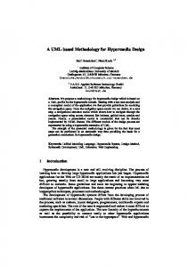
UML Modeling for Instruction Pipeline Design Vipin Saxena, and Deepa Raj The present research work is an attempt for proposing a model for instruction pipeline design through the concepts of UML. This model is designed for the execution of multiple instructions of software programs. These instructions can be executed either in sequential or parallel manner. The class and sequence diagrams are designed and a case study is also reported for the verification of the proposed UML model and performance is also evaluated for the instructions executed in the sequential or parallel manner. By the use of proposed model one can increase the efficiency of the computer system. Earlier software and hardware architecture models are designed on the basis of top down approach but the present model is based upon the bottom up approach which is much faster in comparison of the existing approaches.
Abstract—Unified Modeling language (UML) is one of the important modeling languages used for the visual representation of the research problem. In the present paper, UML model is designed for the Instruction pipeline which is used for the evaluation of the instructions of software programs. The class and sequence diagrams are designed & performance is evaluated for instructions of a sample program through a case study.
Keywords—UML, Instruction Pipeline, Class Diagram & Sequence Diagram. I. INTRODUCTION ML is a powerful modeling language used to represent the research problems visually. A lot of literature is available on modeling problems by the use of UML, but limited research papers are reported in literature on applications of UML for the computer architecture research problems. By the use of UML, software and hardware architecture problems can be solved and performance can be judged after modeling of the problem. Real time system based on UML model is described by Selic and Rumbaugh[1]. The first represented of UML in the field of telecommunication sector is proposed by Holz [2]. The concept of UML was first invented by the Greddy Booch et al. [3]. The UML application is also proposed by the researchers for the web based application & one of the important papers on this is [4]. Various computer architecture models which can be used for the further research work are available in [5]. The latest research in 2007 on distributed computing is reported by the researchers [6]. UML based Vehicle control system is also reported in the literature by Walther et al. [7]. OMG is an important active group for inventing the different versions of the UML. The research papers on these are [8, 9] in which group describes the UML diagram based on XML meta data specification. Performance modeling and prediction tool for parallel and distributed programs are described by Planna et al. [10, 11] and also describe customizing the UML for modeling performance oriented applications. Recently Saxena et al. [12] proposed a UML model with performance computation for the Multiplex System for the processes which are executing in the distributed environment.
U
II. BACKGROUND A. Process Let us first define the process which may be the group or block of instructions of program, macro, sub programs and subroutines. For defining the process, there is a need of the processing element. The processing element is defined as a stereotype and generally used to handle the concurrent processes executing in the parallel and distributed environments. The famous approach to handle the concurrent processes is Torus Topology. Fig. 1 shows the definition of processing unit Base Class
processing_unit process_id :integer process_type :string process_cardinality :integer
Fig. 1 Definition of Processing Unit
Vipin Saxena, Reader & Head, Department of Computer Science, B.B. Ambedkar University (A Central University), Vidya Vihar, Rae Bareli Road, Lucknow, 226025 India (corresponding author, phone:+91-9452372550; fax:+91-522-2440821; e-mail:vsax1@ rediffmail.com). Deepa Raj, Lecturer, Department of Computer Science, B.B. Ambedkar University (A Central University), Vidya Vihar, Rae Bareli Road, Lucknow, 226025 India (e-mail:
[email protected]).
263
World Academy of Science, Engineering and Technology 42 2008
In the Fig. 5 instruction is first fetched (F) from cache memory generally one per cycle and then decoded (D) the instruction according to the resources. In the issue (I) stage, pipeline reserves the right to issue the secure instruction and after this in the several stages, instructions are executed (E) and finally write (W) the results by the Write Back Method. Any Instruction of a program like c = a+b, and c = axb can be computed by the use of the above diagram.
The class diagram of process is defined in Fig. 2. process process_id process_size process_in_time process_out_time process_priority
: integer : integer : string : string : integer
III. PROPOSED UML MODEL The UML modeling is necessary to judge the performance of the instruction pipelining design. The portion of the UML Class Model for the Instruction Pipeline Design is shown below in Fig. 6. In this figure the block or group of instructions of a process are fetched by the Cache Memory which may be the type of instruction cache (I_Cache) and data cache (D_Cache). Instruction cache handles the number of instructions of a program while data cache handles the required data used for execution of the corresponding instruction.
process_create() process_delete() process_update() process_join() process_suspend() process_synchronize()
Fig. 2 Class definition of process
The instance of the process is defined by the use of object xyz which is shown in Fig. 3:
Cache
xyz:process Fig. 3 Instance of class The set of the instances of the class process is modeled by the use of multiple objects which is shown below:
_:process Fig. 4 Multiple instances of object
In above figure _:process shows the name of multiple objects. B. Instruction Pipeline Design Let us define the concept of the instruction pipeline design. In this design, stream of instructions are executed in the overlapped manner by the use of different kinds of buffer. These instructions are executed either in sequential manner or in parallel manner. There are seven stages in the instruction pipeline design which are needed to be model by the use of UML for increasing the efficiency of computer system. The seven stages of instruction pipeline design are shown below in Fig. 5. Fig. 6 UML Class Diagram for Instruction Pipeline Fetch F
Decode D
Issue I
Execute E
Execute E
Execute E
Fig. 5 Seven stages of Instruction Pipeline design
264
Write Back
World Academy of Science, Engineering and Technology 42 2008
Relationships among the classes are shown in given Figure. After fetching the instructions, these are decoded and finally executed in the Arithmetic Logical Unit (ALU class) and outputs are stored into the register file by the use of Write Back Method. The Sequence Diagram for the execution of the instructions of a program is also given in Fig. 7.
ai
bi
R2
R1
0 Multiply unit
R3
R5
R4
s
Add
R1 = a(1) R2 = b(1) ( R1) x (R2) I1: R3 I2 :R4 (R3) I3: R5 (R5) + (R4) Fig. 8 Without Data Forwarding
I1' and I2' can be executed simultaneously with the internal data forwarding. In this, these three instructions are fetched directly into the input register file R4 of above class model. The output of the multiplier is also routed through the register R3. This reduces the total execution time of the three instructions.
Fig. 7 Sequence Diagram of Instruction Pipeline
R 1 = a(1) R2 = b(1) I'1 : R3 I'2: R4 I'3: R5
IV. A CASE STUDY Let us consider the example which is to be executed by the use of proposed UML model. In the instruction pipeline design, there are two techniques used to evaluate the block or group of instructions. These two techniques are known as With Internal Data Forwarding and Without Data Forwarding. In the example, one wants to evaluate S= ∑ aixbi where the range of i=1(1)n. Without data forwarding, the instructions are written by the use of register file in which major portion for the computations are shown by three instructions as shown in Fig. 8. In the block of instructions as shown in figure, the three instructions are executed in the sequential manner and in looping structure by the use of ALU class of above model. With Internal Data Forwarding, the instructions are written below by the use of register file in which major portion for the computations are shown by three instructions. These instructions are shown below as per following Fig. 9. In this
(R1) x (R2) (R1) x (R2) ( R4) + ( R5) ai
bi
R1
R2
0 Multiply unit
R3
R4 R5
Add Unit
Fig. 9 With Internal Data Forwarding
265
World Academy of Science, Engineering and Technology 42 2008
& Software Engineering. Currently he is proposing software designs by the use of Unified Modeling Language for the various research problems related to the Software Domains & Advanced Computer Architecture. He has published more than 60 International and National publications.
In both of the techniques, the numbers of instructions are same but executed in the different manner. The second technique is most popular technique and performance is evaluated and found that the Internal Data Forwarding reduced the total execution time of these three instructions.
Deepa Raj is a Lecturer, Deptt. of Computer Science, Babasaheb Bhimrao Ambedkar University, Lucknow, India. She got her M.Sc. degree in Computer Science from J.K. Institute of Applied Physics & Technology, Allahabad Central University, Allahabad. She has more than eight years teaching experience in field of Computer science. Currently she is solving software designs research problems by the use of Unified Modeling Language (UML). She has several outstanding research papers in this field.
V. CONCLUSION From the above, it is concluded that the UML Class model is a powerful model used to depict the software development problems and the hardware problems. In the Instruction Pipelining Designing, the Internal Data Forwarding saves the execution time of the block or group of instructions of the process. The present work is further extended by considering the different kinds of instructions executed in the different kinds of the buffer known as sequential buffer, loop buffer, target buffer, etc. The present work is considered only for the linear Instruction Pipeline Design therefore, the UML modeling application for Instruction Pipeline Designing can be further extended for the non-linear Instruction Pipeline Designing. REFERENCES [1]
B. Selic, and J. Rumbaugh, "UML for Modeling Complex Real Time Systems", Available Online Via www.rational.com/Products/ Whitepapers/100230.Jsp. [2] E. Holz, "Application of UML within the Scope of New Telecommunication Architectures", GROOM Workshop on UML, Mannheim:Physicaverlag, 1997. [3] G. Booch, J. Rumbaugh and I. Jacobson, "The Unified Modeling Language User Guide", Addision Wesley, Reading, MA, 1999. [4] J. Conallen, "Modeling Web Application Architectures with UML", Communication of the ACM 42(10), pp. 63-70, 1999. [5] K. Hwang. "Advanced Computer Architecture", Tata Mc-Graw Hill, Inc Publishing, 1993. [6] M. Jesus, M. Pedro and S. Alberto, "Applying MDE Methodologies to Design Communication Protocols for Distributed Systems", IEEE Transaction of Software Engineering, April 2007. [7] M. Walther, J. Schirmer, P.T. Flores, A. Lapp, T. Bertram and J. Peterson. "Integration of the Ordering Concept for Vehicle Control System CARTRONIC into the Software Development Process using UML Modeling methods", SAI 2001 World Congress Detroit, Michigan, USA, 2001. [8] OMG ,"Unified Modeling Language Specification", Available Online Via www.omg.org , 2001 [9] OMG," OMG XML Metadata Interchange (XMI) Specification", Available Online Via. www.omg.org, 2002. [10] S. Pllana and T. Fahringer, "UML based Modeling Performance Oriented Applications", 2002 Model Engineering Concepts and Tools, Springer Verlag, Dreseden, Germany, 2002. [11] S. Pllana and T. Fahringer, "UML based Modeling of Performance Oriented Applications", Winter Simulation Conference, USA, 2002. [12] V. Saxena, D. Arora and S. Ahmad, "Object Oriented Distributed Architecture System through UML", IEEE Proceedings International Conference on Advanced in Computer Vision and Information Technology, pp. 305-310, ISBN:978-81-89866-74-7, India, 2007.
Vipin Saxena is a Reader & Head, Deptt. of Computer Science, Babasaheb Bhimrao Ambedkar University, Lucknow, India. He got his M.Phil. Degree in Computer Application in 1991 & Ph.D. Degree work on Scientific Computing from University of Roorkee (renamed as Indian Institute of Technology, India) in 1997. He has more than 12 years teaching experience and 16 years research experience in the field of Scientific Computing
266