IEEE TRANSACTIONS ON POWER DELIVERY, VOL. 29, NO. 4, AUGUST 2014
1901
Unsynchronized Fault Location Based on the Negative-Sequence Voltage Magnitude for Double-Circuit Transmission Lines Behnam Mahamedi and Jian Guo Zhu, Senior Member, IEEE
Abstract—This paper describes a new approach to fault location for double-circuit transmission lines based on only the voltage data of both ends of the faulted circuit. The ratio between the magnitudes of negative-sequence voltages measured at both ends of the faulted circuit is utilized to estimate the fault location. Since only the magnitudes are used, the data of both ends are not required to be synchronized, which removes any concern about data synchronization. Moreover, since only the voltage data are required, the errors caused by current transformers can be avoided. The proposed method can effectively locate the single-phase-to-ground, doublephase-to-ground, and phase-to-phase faults disregarding the fault resistance and prefault conditions and without any need for fault classification and phase selection. Unlike the iterative methods, the proposed method is fully analytical and does not cause much computing burden to the line relays. The accuracy and practicality of the proposed method make it an attractive function to implement in numerical relays. Index Terms—Double-circuit transmission line, fault location, negative-sequence reactance, negative-sequence voltage magnitude, unsynchronized measurement.
NOMENCLATURE and
Negative-sequence reactance behind relays and , respectively. Negative-sequence reactance of a transmission line.
and
Negative-sequence voltage measured by relays and , respectively. Negative-sequence voltage at the fault point.
and
and
Negative-sequence capacitance and capacitive reactance of a transmission line, respectively. Equivalent capacitance at the sending and receiving ends, respectively.
Manuscript received June 09, 2013; revised October 30, 2013; accepted December 04, 2013. Date of publication January 28, 2014; date of current version July 21, 2014. Paper no. TPWRD-00660-2013. B. Mahamedi was with the School of Electrical, Mechanical and Mechatronic Systems, University of Technology Sydney, Ultimo NSW 2007, Australia. He is now with the Iran Grid Management Company, Tehran IR-15175-648, Iran (e-mail:
[email protected]). J. G. Zhu is with the School of Electrical, Mechanical and Mechatronic Systems, University of Technology Sydney, Ultimo NSW 2007, Australia (e-mail:
[email protected]). Digital Object Identifier 10.1109/TPWRD.2013.2294972
Ratio between the magnitudes of negative-sequence voltages at the local and remote ends. Fault location in the faulted circuit of the double-circuit transmission line in per unit. I. INTRODUCTION
D
OUBLE-CIRCUIT transmission lines have been adopted in modern power systems to increase the transmission capacity and to enhance reliability and security. However, protecting double-circuit lines, in particular locating faults on them, are always challenging due to the mutual coupling between zero-sequence components of the two circuits. Whether they are for single-circuit or double-circuit transmission lines, there are two types of fault-location methods known as one-end-based and two-end-based ones. The one-end-based methods [1], [2] may suffer from errors due to the variations of source impedance, fault incidence angle, and loading conditions while their major merit is that they need data of only one end [3]. To overcome the shortfalls of one-end-based methods, two-end-based methods were introduced. They can be classified into unsynchronized and synchronized ones. Unsynchronized methods do not need the data of both line ends to be synchronized while data synchronization is the first step in the synchronized methods. Up till now, several methods have been proposed for fault location on double-circuit transmission lines, most of which require data of both voltage and current [4]–[11]. The magnetic saturation of current transformers (CTs) always presents challenges of having reliable current data and, thus, a strong desire for possible approaches based on only voltage data exists. Chen et al. [4] presented a fault-location method based on the distributed line model. This method requires the phasor measurement units (PMUs) for synchronized data and continuous monitoring of the line under normal operation. Funabashi et al. [5] presented two algorithms for multiterminal double-circuit transmission lines based on “impedance calculation” and “current diversion ratio.” The synchronization for voltages and currents at all terminals is required. Kang et al. [6] developed a fault-location algorithm for untransposed double-circuit transmission lines based on the lumped parameter model of transmission lines by ignoring the line shunt capacitances. This may cause significant errors in long transmission lines. Besides, fault classification is required for fault location. Izykowski et al. [7]
0885-8977 © 2014 IEEE. Personal use is permitted, but republication/redistribution requires IEEE permission. See http://www.ieee.org/publications_standards/publications/rights/index.html for more information.
1902
IEEE TRANSACTIONS ON POWER DELIVERY, VOL. 29, NO. 4, AUGUST 2014
proposed a method which requires the voltage and current data of faulted and healthy circuits, but the measurement from the healthy circuit is not always available. Apostolopoulos and Korres [8] put forward an algorithm based on the positive-sequence current without utilizing the line parameters, which requires prefault and postfault data. Kang and Liao [9] proposed a method using synchronized current phasors. The data synchronization of various busbars, however, requires PMUs to be installed on these busbars. Apostolopoulos and Korres [10] proposed an iteration-based method, but multiple iterations can cause heavy computing burden on the relays. Song et al. [11] described a time-domain fault-location algorithm for parallel transmission lines using currents of both ends based on a differential component net. The sampling frequency required for the method is much higher than the practical one that is around 1 kHz [12]. Assuming both relays are provided with the source impedance behind them, which are available at load dispatch centers [13], this paper presents a new fault-location method for double-circuit transmission lines using the magnitudes of negative-sequence voltages measured at both ends of the faulted circuit. The faulted circuit is assumed to be known based on distance relays action and circuit-breaker (CB) status. In this method, fault classification is not required to estimate fault location. This is a specific feature in comparison to the fault locators that need to first classify the fault type. One interesting attribute of the proposed method is that the fault-location accuracy still remains high for long transmission lines even when the lumped model is employed. It is true since the proposed method uses only the voltage data and the ratio between voltages of both ends. Moreover, the proposed method is fully analytical even when the shunt capacitances are considered. The accuracy of the method, together with its practicality, makes it an attractive option to implement in the relays as a fault-location function. The proposed method is a modified and extended version of the one proposed in [14]. The rest of this paper is organized as follows. Section II presents a detailed description of the proposed method, and Section III investigates the effects of the line shunt capacitances on the derived equations. Section IV is devoted to studying the sensitivity of the proposed method to the parameters which are required for fault location. Section V presents the numerical simulation to demonstrate the proposed method. The simulation results were obtained by using the steady-state data of postfault analysis carried out in MATLAB/SIMULINK. Finally, conclusions are drawn in Section VI.
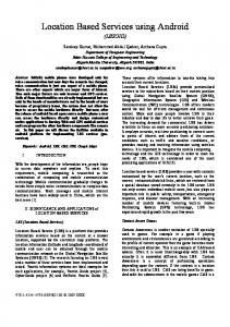
Fig. 1. Double-circuit transmission line protected by the distance relays of and . sending and receiving ends,
Fig. 2. Negative-sequence circuit of the double-circuit transmission line for an . unbalanced fault occurring at location (in per unit) from relay
negative-sequence circuit can thus be modeled as shown in Fig. 2. Converting the delta connection formed by the healthy circuit reactance and the source reactances to Y connection, the negative-sequence circuit can be represented in a new form as shown in Fig. 3, where , and can be obtained from Fig. 2 as (1) (2) (3) and (4)
II. PROPOSED METHOD Consider a double-circuit transmission line as shown in Fig. 1, which is protected by distance relays and . The relays are fed by only voltage transformers to emphasize that the proposed method is based on only the voltage data. In transmission systems, the resistances are negligible in comparison to the reactances [15], and the mutual coupling between the negative-sequence components of each circuit is also negligible [16]. If an unbalanced fault occurs at distance [per unit (p.u.)] from relay in one circuit of the line, the
From Fig. 3, the following equations can be derived:
(5)
MAHAMEDI AND ZHU: UNSYNCHRONIZED FAULT LOCATION BASED ON THE NEGATIVE-SEQUENCE VOLTAGE MAGNITUDE
1903
Fig. 4. Line shunt capacitances considered in the negative-sequence circuit of the double-circuit transmission line.
Fig. 3. Negative-sequence circuit of the double-circuit transmission line after converting the delta connection to the Y connection.
(6) is the voltage between the fault point and the star where point of the Y connection in the negative-sequence circuit. Considering only the phasor magnitudes and dividing (5) by (6) yields
(7) Solving (7) in terms of
leads to (8)
As a result, knowing (the ratio between the magnitudes of negative-sequence voltages at the sending, S, and receiving, R, ends of the faulted circuit) and the negative-sequence reactances of the sources and that of the line, the fault location in a doublecircuit transmission line can be estimated by using (8).
Here, it can be argued that the same results can also be obtained by using the zero-sequence circuit. The following outlines the reasons why the negative-sequence circuit rather than the zero-sequence one was chosen. The first and an evident one is that the zero-sequence circuit does not exist in the case of ungrounded faults. The second is that there is mutual coupling between zero-sequence components of two circuits in double-circuit transmission lines. The third is that the zero-sequence parameters are not as accurate as the negative-sequence ones due to some unknown parameters that contribute to the zero-sequence circuits. Finally, it should be mentioned that the zero-sequence resistances cannot be assumed negligible in comparison to the zero-sequence reactances for developing a fault-location method since it might result in a large error. This assumption may, however, work well in other applications, such as fault detection and classification [17]. III. CONSIDERATION OF SHUNT CAPACITANCES To consider the effects of the line shunt capacitances on the proposed method, a PI model for the double-circuit transmission line is used. The PI model is quite accurate to obtain steadystate results where the shunt capacitances should be considered [18]. Based on the PI model, if an unbalanced fault occurs at location m (in p.u.) from relay in one circuit of the doublecircuit transmission line, the negative-sequence circuit will be as shown in Fig. 4. The capacitances of the healthy circuit are parallel to those of the faulted circuit at the sending and receiving ends. The equal capacitances at the sending and receiving ends will then be obtained as follows: (9) (10)
1904
IEEE TRANSACTIONS ON POWER DELIVERY, VOL. 29, NO. 4, AUGUST 2014
The equal capacitances given in (9) and (10) are parallel with the source reactances and , respectively. Thus, two new source reactances and will be formed by the parallel combination of the source reactances and the equal capacitances as
TABLE I DIFFERENT FAULT CASES CONSIDERED FOR EVALUATION STUDIES
(11)
(12) Substituting obtains as
and
as
and
in (8), one Similarly, sensitivity factors can be obtained by using (13) when line shunt capacitances are considered. (13)
IV. SENSITIVITY ANALYSIS It is a worthy practice to study the sensitivity of the proposed method to the required parameters. As shown in (8) and (13), the source parameters and and line parameters and are required for estimation of fault location. The line reactance and capacitance can be accurately measured but the source reactances may not be obtained as accurately as the line parameters. Therefore, the sensitivity of fault-location estimation to the source reactances should be studied. Here, one-at-a time (OAT) normalized local sensitivity analysis is adopted, which is a basic approach in sensitivity analysis. It is assumed that the expected value of (the ratio of negative-sequence voltage magnitude at the sending-end relay to the one at the receiving-end relay) is first measured while the fault location varies along the line. Having known the variation of , the sensitivity of fault location to the aforementioned parameters will be obtained as follows. Taking the derivative of (8) in terms of yields the sensitivity factor to the source reactance behind the sending-end relay as
(14) The sensitivity factor to the source reactance behind the receiving-end relay is obtained by taking the derivative of (8) in terms of as
(15)
V. EVALUATION AND SIMULATION RESULTS A 400-kV, 50-Hz double-circuit transmission line of 200-km length illustrated in Fig. 1 was chosen to evaluate the accuracy of the proposed method. The parameters of the transmission line and those of the sources are given in the Appendix. Since the proposed method is based on the voltage data, capacitive voltage transformers (CVTs) were modeled in detail as per data given in [19]. Also, the fault inception time was chosen as 0.1 s. The negative-sequence voltage magnitude was calculated by the discrete Fourier transform (DFT) as one of the most common approaches. Different fault cases presented in Table I were considered to evaluate the proposed method. A. Accuracy Evaluation Figs. 5–13 show the estimation errors of fault location for the different fault cases of Table I. The errors were calculated by Estimation error% Actual location - Estimated location Total line length (16) To provide a better vision of the accuracy of the method, here it is preferred to present the real value of the percentage errors, not their absolute values. The absolute values of the estimation errors Error (%) have been used to provide the maximal and mean values of the errors shown in Table II. The mean values for each fault case have been calculated by averaging out all of the absolute errors obtained at different fault locations (every 1 km along the line). The results confirm that the proposed fault-location method is independent of the fault type and fault resistance. This can also be inferred from the discussion presented in Sections II and III. The small difference in the estimation errors when the fault type and fault resistance vary can be attributed to the errors generated by the instrument transformers (CVTs) and numerical calculation. It can be seen that the accuracy of the method will be quite high if the required parameters are close enough to their real values.
MAHAMEDI AND ZHU: UNSYNCHRONIZED FAULT LOCATION BASED ON THE NEGATIVE-SEQUENCE VOLTAGE MAGNITUDE
Fig. 5. Estimation errors for Case 1 based on the lumped and PI model.
Fig. 9. Estimation errors for Case 5 based on the lumped and PI model.
Fig. 6. Estimation errors for Case 2 based on the lumped and PI model.
Fig. 10. Estimation errors for Case 6 based on the lumped and PI model.
Fig. 7. Estimation errors for Case 3 based on the lumped and PI model.
Fig. 11. Estimation errors for Case 7 based on the lumped and PI model.
Fig. 8. Estimation errors for Case 4 based on the lumped and PI model.
B. Sensitivity Evaluation Fig. 14 shows the measured value of for different fault locations in the simulated system. The normalized sensitivity factors to and are, respectively, represented by and and shown in Figs. 15 and 16. It can be seen that for fault locations of more than 0.2 p.u., both sensitivity factors are less than 1,
1905
which indicates a low sensitivity of the method to the variation of source reactances. For instance, and are, respectively, calculated as 0.66 and 0.75 at 0.3. If is given with 10% tolerance, the fault location will be estimated in the range of [0.280, 0.320]. For with a tolerance of 10%, the fault location will be estimated in the range of [0.277, 0.323]. In case of a fault location farther from relay , the accuracy will even be higher. The aforementioned sensitivity factors were obtained based on OAT sensitivity analysis illustrated in Section IV. Here, it is worth investigating how much the estimation errors would be if both source reactances simultaneously deviate from their real values and . To do this, it was assumed that the source reactances used for estimation are given either 110% or 90% of their real values. In this sense, four possible cases for the source reactances emerged as 1) 1.1 X , 1.1 X ; 2) 0.9 X , 0.9 X ; 3) 1.1 X , 0.9 X ; and 4) 0.9 X , 1.1 X . Figs. 17–20 show the estimation errors for each case. As shown, even though both source reactances
1906
IEEE TRANSACTIONS ON POWER DELIVERY, VOL. 29, NO. 4, AUGUST 2014
Fig. 12. Estimation errors for Case 8 based on the lumped and PI model.
Fig. 15. Sensitivity factor to the source reactance behind the sending-end relay for different fault locations based on the lumped model.
Fig. 13. Estimation errors for Case 9 based on the lumped and PI model. TABLE II MAXIMAL AND MEAN VALUES OF ABSOLUTE ERRORS FOR EACH FAULT CASE BASED ON THE LUMPED AND PI MODELS
Fig. 16. Sensitivity factor to the source reactance behind the receiving-end relay for different fault locations based on the lumped model.
Fig. 17. Estimation errors for a deviation of 10% in source reactances (case: 1.1 X and 1.1 X ).
VI. CONCLUSION
Fig. 14. Variation of
for different fault locations.
deviate 10% from their real values at the same time, the estimation errors still fall in a reasonable range with a maximum error of 5%.
A new fault-location method for double-circuit transmission lines is proposed in this paper. It is a steady-state-based method based on the ratio of negative-sequence voltage magnitudes at both ends of the line. The evaluation results are encouraging and have shown the practicality of the proposed method for implementation in real applications. The proposed concept can be readily developed for single-circuit transmission lines as well. The major advantages of the proposed method can be summarized as follows. • The proposed method considers the lumped parameter and PI models of a transmission line. It was found that even
1907
MAHAMEDI AND ZHU: UNSYNCHRONIZED FAULT LOCATION BASED ON THE NEGATIVE-SEQUENCE VOLTAGE MAGNITUDE
• Another interesting feature of the proposed method is that it requires only the magnitudes of negative-sequence voltages, which completely removes the need for synchronization. • The proposed method is a purely analytical method, which effectively eliminates the computing burden to the relay. • The only type of fault that cannot be located by the proposed method is the three-phase fault which hardly occurs on transmission lines.
Fig. 18. Estimation errors for deviation of 10% in source reactances (case: 0.9 X and 0.9 X ).
APPENDIX The parameters of the simulated system are given as follows. The positive-, negative- and zero-sequence impedances behind relay are
The voltage of the source behind relay
is
The positive-, negative- and zero-sequence impedances behind relay are Fig. 19. Estimation errors for deviation of 10% in source reactances (case: 1.1 X and 0.9 X ).
The voltage of source behind relay
is
The distributed model parameters of the double-circuit transmission line: The positive-, negative-, and zero-sequence impedances are
Fig. 20. Estimation errors for deviation of 10% in source reactances (case: 0.9 X and 1.1 X ).
by considering the lumped parameter model the estimation errors are small for a long transmission line. The reason is that the proposed method does not use the current data and requires only the ratio between voltage magnitudes. Other existing methods may fail for long transmission lines if they do not consider shunt capacitances. • Most of the existing methods require both voltage and current data at either one or both ends of a transmission line. Since the proposed method needs only the voltage data at both ends of the line, it eliminates the errors produced by the CT measurement. • One of the attributes of the proposed method is that it is independent of the fault resistance and fault type. The small differences in the estimation errors for different fault types and fault resistances are due to CVT measurement affected by the transients which contribute to computing errors.
The mutual coupling impedance between the zero-sequence circuits is
The positive-, negative-, and zero-sequence capacitances are
The mutual coupling capacitance between the zero-sequence circuits is
REFERENCES [1] T. Kawady and J. Stenzel, “A practical fault location approach for double circuit transmission lines using single end data,” IEEE Trans. Power Del., vol. 18, no. 4, pp. 1166–1173, Oct. 2003.
1908
[2] G. Song, J. Suonan, and Y. Ge, “An accurate fault location algorithm for parallel transmission lines using one-terminal data,” Elect. Power Energy Syst., vol. 31, no. 2–3, pp. 124–129, 2009. [3] J.-A. Jiang, J.-Z. Yang, Y.-H. Lin, C.-W. Liu, and J.-C. Ma, “An adaptive PMU based fault detection/location technique for transmission lines part I: Theory and algorithms,” IEEE Trans. Power Del., vol. 15, no. 2, pp. 486–493, Apr. 2000. [4] C. S. Chen, C. W. Liu, and J.-A. Jiang, “A new adaptive PMU based protection scheme for transposed/untransposed parallel transmission lines,” IEEE Trans. Power Del., vol. 17, no. 2, pp. 395–404, Apr. 2002. [5] T. Funabashi, H. Otoguro, Y. Mizuma, L. Dube, and A. Ametani, “Digital fault location for parallel double-circuit multi-terminal transmission lines,” IEEE. Trans. Power. Del., vol. 15, no. 2, pp. 531–537, Apr. 2000. [6] S. Kang, Y. Ahn, Y. Kang, and S. Nam, “A fault location algorithm based on circuit analysis for untransposed parallel transmission lines,” IEEE Trans. Power Del., vol. 24, no. 4, pp. 1850–1856, Oct. 2009. [7] J. Izykowski, E. Rosolowski, and M. M. Saha, “Locating faults in parallel transmission lines under availability of complete measurements at one end,” Proc. Inst. Elect. Eng., Gen., Transm. Distrib., vol. 151, no. 2, pp. 268–273, Mar. 2004. [8] C. A. Apostolopoulos and G. N. Korres, “A novel fault-location algorithm for double-circuit transmission lines without utilizing line parameters,” IEEE. Trans. Power. Del., vol. 26, no. 3, pp. 1467–1478, Jul. 2011. [9] N. Kang and Y. Liao, “Double-circuit transmission-line fault location utilizing synchronized current phasors,” IEEE. Trans. Power. Del., vol. 28, no. 2, pp. 1040–1047, Apr. 2013. [10] C. A. Apostolopoulos and G. N. Korres, “Accurate fault location algorithm for double-circuit series compensated lines using a limited number of two-end synchronized measurements,” Elect. Power Energy Syst., vol. 42, no. 1, pp. 495–507, 2012. [11] G. Song, J. Suonan, Q. Xu, P. Chen, and Y. Ge, “Parallel transmission lines fault location algorithm based on differential component net,” IEEE Trans. Power Del., vol. 20, no. 4, pp. 2396–2406, Oct. 2005. [12] I. Zamora, A. J. Mazón, V. Valverde, E. Torres, and A. Dysko, “Power quality and digital protection relays,” presented at the Int. Conf. Renew. Energies Power Qual., Barcelona, Spain, 2004. [13] S. M. Brahma and A. A. Girgis, “Fault location on a transmission line using synchronized voltage measurements,” IEEE Trans. Power Del., vol. 19, no. 4, pp. 1619–1622, Oct. 2004. [14] Y. Liao, “Fault location utilizing unsynchronized voltage measurements during fault,” Elect. Power Compon. Syst., vol. 34, no. 12, pp. 1283–1293, 2006. [15] H. Saadat, Power System Analysis, 2nd ed. New York: McGraw-Hill, 2002.
IEEE TRANSACTIONS ON POWER DELIVERY, VOL. 29, NO. 4, AUGUST 2014
[16] A. Apostolov, D. Tholomier, S. Sambasivan, and S. Richards, “Protection of double circuit transmission lines,” presented at the 60th Annu. Conf. Protect. Relay Eng., College Station, TX, USA, Mar. 2007. [17] B. Mahamedi and J. G. Zhu, “Fault classification and faulted phase selection based on the symmetrical components of reactive power for single-circuit transmission lines,” IEEE Trans. Power Del., vol. 28, no. 4, pp. 2326–2332, Oct. 2013. [18] O. Hevia, Alternative Transients Program—Comparison of transmission line models. [Online]. Available: www.iitreeunlp.org.ar/caue/Archivos/emodlin.pdf [19] D. Tziouvaras et al., “Mathematical models for current, voltage and coupling capacitor voltage transformers,” IEEE Trans. Power Del., vol. 15, no. 1, pp. 62–72, Jan. 2000.
Behnam Mahamedi was born in Tehran, Iran, in 1982. He received the B.Sc. degree in electrical engineering from Iran University of Science and Technology (IUST), Tehran, in 2005 and the M.Sc. degree in electrical engineering from Shahid Beheshti University (SBU), Tehran, in 2010. From 2012 to 2013, he was a Researcher with the University of Technology Sydney (UTS), Sydney, Australia, focusing on power system fault detection systems. Since 2008, he has been a Protection Engineer with the Iran Grid Management Company (IGMC), Tehran. His research interests are power system protection, power system transients, and wavelet-transform applications in power systems.
Jian Guo Zhu (SM’03) received the B.E. degree in electrical engineering from Jiangsu Institute of Technology, Zhenjiang, China, in 1982, the M.E. degree in electrical engineering from Shanghai University of Technology, Shanghai, China, in 1987, and the Ph.D. degree in electrical engineering from the University of Technology Sydney (UTS), Sydney, Australia, in 1995. Currently, he is a Professor of Electrical Engineering and Head of the School of Electrical, Mechanical, and Mechatronic Systems, UTS. His research interests include electromagnetic and magnetic properties of materials, electrical machines and drives, power electronics, and renewable energy systems.