2752
IEEE TRANSACTIONS ON POWER DELIVERY, VOL. 26, NO. 4, OCTOBER 2011
Wide-Area Backup Protection Algorithm Based on Fault Component Voltage Distribution Zhiqin He, Student Member, IEEE, Zhe Zhang, Wei Chen, Member, IEEE, Om P. Malik, Life Fellow, IEEE, and Xianggen Yin, Member, IEEE
Abstract—A new wide-area backup protection algorithm based on the fault component voltage distribution is proposed in this paper. It is helpful to overcome the problems of complex setting and maloperation under flow transfer of conventional backup protection. The measured values of fault component voltage and current at one terminal of the transmission line are applied to estimate the fault component voltage at the other terminal. Then, the fault element can be identified by the ratio between the measured values and the estimated values. In addition, the speed of fault element identification can be accelerated by a faulted area detection scheme. The proposed method has the advantage of easy setting and low requirement for synchronized wide-area data. The studies performed on the IEEE 39-bus system validate the proposed algorithm under various faults and flow transfer. Index Terms—Fault element identification, fault voltage ratio coefficient, faulted area detection, regional centralized, wide-area backup protection.
I. INTRODUCTION
ROTECTIVE relaying provides important safeguard for power grid operation. Conventional backup protection depends on local electrical information to make relevant decisions, and cannot securely distinguish an internal fault from heavy load during flow transfer [1]. This may cause cascading trip events and accelerate power system collapse. Moreover, the complex setting principle of conventional backup protection may induce hidden failures caused by setting mistakes [2], which would increase the risk of system instability during a disturbance. With the development of wide area measurement system (WAMS), novel system protection techniques based on wide-area information (WAI) have attracted significant attention [3], [4]. The current literature about it can be classified into two categories: 1) literature dedicated to enhancing the
P
Manuscript received February 11, 2011; revised May 14, 2011; accepted August 15, 2011. Date of current version October 07, 2011. This work was supported in part by the National Natural Science Foundation of China (No. 50837002, 50877031) and in part by the Fundamental Research Funds for the Central Universities (HUST: 2010MS120). Paper no. TPWRD-00102-2011. Z. He, Z. Zhang, W. Chen, and X. Yin are with the State Key Laboratory of Advanced Electromagnetic Engineering and Technology, Huazhong University of Science and Technology, Wuhan 430074, China (e-mail:
[email protected];
[email protected];
[email protected]. edu.cn;
[email protected]). O. P. Malik is with the University of Calgary, Calgary, AB T2N 1N4, Canada (e-mail:
[email protected]). Color versions of one or more of the figures in this paper are available online at http://ieeexplore.ieee.org. Digital Object Identifier 10.1109/TPWRD.2011.2165971
property of system stability control [5] and 2) literature dedicated to improving the performance of conventional protection [6]. The wide-area backup protection (WABP) based on fault element identification (FEI), a hot topic of investigation these days, belongs to the second category [7]–[13]. It works like this: first, the WAI is used to identify the fault element within the protected zone. Then, the fault isolation is realized by simple sequence coordination among incident breakers. This method could overcome the drawbacks of conventional backup protection and effectively prevent cascading outages. The kernel of WABP is to identify the fault elements based on WAI. Two most widely used algorithms are: wide-area current differential and wide-area directional pilot protection. In a distributed current differential scheme presented in [7], intelligent electronic devices (IEDs) in the same protected zone exchange information among each other through a multiagent approach to complete the computation and sequential trip function. A WABP system based on Agent Petri net, proposed in [8], uses a Petri net to establish a simulated environment to evaluate the property of protection agents within the WABP system. It also proposes a negotiation mechanism among protection agents in the case of information error or information loss, which improves the fault-tolerance ability of the current differential algorithm. Generally speaking, wide-area current differential protection has simple principle, but the high dependency on data synchronism and the large imbalance current caused by cumulative error of multipoint measurements can deteriorate its reliability and sensitivity [9]. Compared to the wide-area current differential method, the wide-area directional pilot algorithm could quickly identify fault elements through sequence directional criterion and impedance criterion without high requirement for data synchronization [10]. When a failure of the substation battery occurs, the direction comparison scope of the protection system will expand automatically to search faulty elements reliably [11], [12]. However, conventional directional pilot protection is subject to the influence of several factors, such as high-impedance earth faults, two-phase operation of transmission line, evolved faults (e.g., a fault starting as an external fault, and evolving to internal fault), etc. In order to simplify the calculation of FEI, the faulted area detection (FAD) algorithm has been proposed in recent years. The distribution characteristic of bus positive-sequence voltage is utilized in [13] to detect the bus closest to the fault location, thus reducing the number of lines requiring the calculation of current differential. However, the sensitivity of the substation pickup criterion and the reliability of the bus voltage sorting
0885-8977/$26.00 © 2011 IEEE
HE et al.: WIDE-AREA BACKUP PROTECTION ALGORITHM BASED ON FAULT COMPONENT VOLTAGE DISTRIBUTION
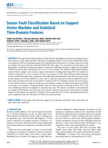
Fig. 1. Fault component network of a two-terminal system. (a) External fault. (b) Internal fault.
scheme remain to be further improved. Also, how to prevent communication congestion is another issue that remains to be solved. This paper presents a new WABP algorithm based on fault component voltage distribution, which mainly comprises two parts: FEI and FAD. The fault component voltage at one terminal of the transmission line is estimated by the fault component voltage and current at the other terminal. The ratio between the measured values and the estimated values is applied to identify the faulty element. Meanwhile, the faulted area is detected through FAD. Only the substations within the faulted area need to transmit information to the regional central station of the WABP system. Then, the regional central station will search the suspected faulty lines (SFLs) and identify actual faulty lines quickly. Simulation results validate the security and sensitivity of this method under several complex conditions, such as high-impedance earth faults, two-phase operation of line, evolved faults, and flow transfer.
Fig. 2. Distribution of the measured and estimated fault component voltages. (a) External fault. (b) Internal fault.
The fault component voltage at one terminal of the transmission line can be estimated by the fault component voltage and current at the other terminal and the line impedance. The estimation equation is given by (1) where , are the estimated values of the bus fault com, are the corresponding measured ponent voltage, and fault component voltages. The distribution of the measured and estimated fault component voltages is shown in Fig. 2. Define a fault voltage ratio coefficient (FVRC) for each end of the line as (2)
Then, the maximum value of FVRC of the two terminals can be adopted as the operating parameter of protection
II. FAULT ELEMENT IDENTIFICATION A. Basic Principle For a two-terminal system, the voltage at one terminal can be estimated correctly by the measured voltage and current at the opposite terminal when the system operates normally or an external fault occurs. However, the estimated and the measured voltages are quite different due to the presence of the fault branch when an internal fault occurs. The proposed FEI algorithm is established based on this characteristic. The fault component network of a two-terminal system is shown in Fig. 1 with the external and internal faults located at , , respectively. In Fig. 1, and represent the equivais the transmission lent system impedance of both terminals, is the ground fault resistance, and is line impedance. the fault component source at the fault point. , whose value, in the range represents the ratio of the distance from the fault point to side “m” and the total line length.
2753
(3) Obviously, the measured values and the estimated values are equal when an external fault occurs, that is . In conis greater than 1 when an internal fault occurs. Thus, trast, the faulty lines can be identified by means of . B. Comprehensive Criteria The principle of FEI is applicable to all types of fault components, including positive-, negative-, and zero-sequence fault components. A comprehensive criterion of FEI can be established by combining these three fault components. From (1), the estimation equation of fault components at side “m” is described as (4)
2754
IEEE TRANSACTIONS ON POWER DELIVERY, VOL. 26, NO. 4, OCTOBER 2011
From the aforementioned description, it is easy to prove the availability of this algorithm under the conditions of two-phase operation of line, evolved faults, and flow transfer. C. Characteristic Analysis 1) Effect of Ground Fault Impedance: As shown in Fig. 1(b), the measured values of fault component voltages of both terminals can be calculated by
Fig. 3. Tripping logic of the positive-sequence fault component.
where , , and represent the measured values of positive-, negative-, and zero-sequence component of the fault , correspond to the estimated voltage of side “n.” values of side “m.” Hence, the FVRC of side “m” is defined as
(5)
The FVRC of side “n” can be calculated similarly. The positive-sequence fault component could identify all types of faults, whether symmetrical or asymmetrical, but the duration of its existence is short [14] and additional measures are needed when it is applied as a backup protection. Therefore, the negativeand zero-sequence components can be used to identify asymmetrical faults because of their long-term existence. In order to guarantee the sensitivity of operating criterion, negative- and zero-sequence components are combined to identify earth faults
(9) can be where symbol “ ” denotes the parallel connection. estimated according to (1). Then, the FVRC of each of the two terminals can be expressed as follows:
(10)
(6) Likewise, the negative-sequence component can be applied to identify phase-to-phase faults (7) A symmetrical fault can be identified by the positive-sequence fault component criterion accompanied with the low-voltage auxiliary criterion (8) where is the setting value of criteria (6)–(8). In order to overcome the influence of the system operation mode switch should be set as 1.2 with a 20% and measurement errors, margin 1.2 1.0)/1.0 0.2 . , are the positive-seis the rated voltage magquence voltages of both terminals, is the low-voltage coefficient. In order nitude of line, and to distinguish the abnormal voltage state from normal voltage can be set as 0.5. The tripping logic of the fluctuations, positive-sequence fault component is shown in Fig. 3. For different types of faults, substations within a protected zone could estimate relevant fault component voltages, and then send the estimated and measured values to the regional central station of the WABP system. Obviously, the proposed scheme just needs to compare the magnitude of fault component voltages without requiring highly synchronized phasor information.
and are independent of . Therefore, It is clear that in theory, the FEI algorithm would not be affected by ground fault impedance. 2) Effect of Fault Position, System, and Line Impedance: should be In order to clear an internal fault correctly, greater than 1.2. According to (10), FVRC depends on system impedance, line impedance, and fault position. These parameters thus affect the performance of FEI. Suppose that the ratios of the system and the line impedances and , respectively. at two ends are Neglect the influence of system and line resistances, and can be expressed by real numbers, and the expression of FVRC can be changed into (11) . The distribuAssume that and are constants, and tion of FVRC is shown in Fig. 4. The sensitivity of the FEI algorithm decreases gradually when the fault position moves from one end to the middle of the line. , the operating parameter If an internal fault is located at will have the minimum value, creating the least favorable be equal to . Then, (10) can be condition for FEI. Let rewritten as (12)
HE et al.: WIDE-AREA BACKUP PROTECTION ALGORITHM BASED ON FAULT COMPONENT VOLTAGE DISTRIBUTION
2755
the approximate nonoperation zone of FEI corresponds to the shaded region in Fig. 5, and can be indicated as
(16) It is clear that the sensitivity deficiency of FEI would only occur when the system impedances of both terminals of the line are much greater than the line impedance simultaneously. However, the equivalent system impedance is generally smaller in the actual high-voltage and extra-high voltage (EHV) grid. Besides, the zero-sequence impedance of the transmission line is larger than positive-sequence impedance, and the zero-sequence system impedances of both terminals are restricted by the leakage reactance of transformers, the neutrals of which are grounded. Therefore, the earth fault whose frequency of occurrence is much higher than the other faults can be cleared with higher sensitivity. In short, the operating criteria of the FEI algorithm presented in this paper have high availability in a practical EHV network.
Fig. 4. Distribution of FVRC.
III. FAULTED AREA DETECTION
Fig. 5. Operation characteristic of FEI.
Therefore, it can be solved as
(13) According to (11) and (13), the minimum value of
is
The WABP system identifies fault elements by integrating multipoint information within a regional grid. For actual power grids, which are large in scale and contain a large number of substations, if every substation within the protected zone sends electrical information to the regional central station, communication congestion may occur, which may affect the performance of WABP. Therefore, the most important problem yet to be solved for the WABP system is to reduce the network communication traffic and accelerate FEI computation. A new FAD method based on sequence voltage distribution is presented here. When a fault occurs, the substation pickup detection will be implemented first, and only those pickup substations need to upload information. Then, the regional central station will detect the SFLs and realize the function of FEI. A. Substation Pickup Detection
(14)
Let
1.2, the nonoperation zone of FEI is
The bus voltages and branch currents of each substation in the protected zone will fluctuate to varying degrees when a fault occurs, but only the substations close to the fault point would pick up for their high sensitivity. Therefore, the faulted area can be detected according to the substation pickup criteria. The negative- and zero-sequence voltages and currents can be utilized to reflect asymmetrical faults, and the corresponding pickup criterion is defined as
(15)
(17)
In (15), and are 2-D variables. Let , be in the range (0, 10). The operation characteristic of FEI can be then shown as in Fig. 5. In order to demonstrate the influence of and intuitively, the operation boundary shown in Fig. 5 can be simulated approximately by three lines tangent to the actual boundary. Thus,
where and are the negative- and zero-sequence bus voltages of substation “m,” and stand for the maximum negative- and zero-sequence currents of incident and are the branches connected to substation “m,” and rated voltage magnitude of the bus and the rated current mag, , , and are the nitude of the branch.
2756
IEEE TRANSACTIONS ON POWER DELIVERY, VOL. 26, NO. 4, OCTOBER 2011
proportional coefficients of negative- and zero-sequence components, and can be set as 0.1. Taking advantage of the synthesized information from negative- and zero-sequence components and adopting low setting values could improve the sensitivity of pickup criterion under different complex conditions, such as high-impedance earth faults, etc. As shown in (7), phase-to-phase fault identification only uses negative-sequence components. Thus, a criterion shown in (18) is added to distinguish the fault type after substation “m” picks up (18) If criterion (18) is satisfied, the negative-sequence component should be uploaded. Otherwise, the negative and zero-sequence components should be sent together. If criterion (17) is not satisfied, each substation will implement symmetrical fault pickup criterion as
Fig. 6. Structure of the WABP system.
IV. WABP SCHEME (19) can be set as 0.5. where the proportional coefficient Adopting the high setting value in response to a symmetrical fault is adequate due to the high impedance being neglected under this condition [1]. On the other hand, it is helpful to avoid frequent pickup of the WABP system under normal switching of the power system. Afterwards, the measured fault component voltages of substation “m” and the estimated fault component voltages of adjacent substations are sent to the regional central station. Note and the posthat the positive-sequence voltage magnitude itive-sequence fault component voltage magnitude are both uploaded when a symmetrical fault occurs. The former is used to detect fault incident buses (FIBs) and the latter to identify fault elements. B. Suspected Faulty Lines Detection After collecting the uploaded data, the regional central station will sort the measured sequence voltages and locate the FIBs which are closest to the fault point. Ideally, the bus with the maximum negative- or zero-sequence voltage magnitude or with the minimum positive-sequence voltage magnitude would be regarded as FIB. But in the actual grid, the FIBs search is affected by several factors, such as measurement error from each substation. Therefore, the first three buses in the sorting series can be selected as FIBs to ensure the redundancy of the sorting computation. FIBs correspond to three buses with the highest zero-sequence voltage when earth faults occur, and to three buses with the highest negative-sequence voltage or lowest positive-sequence voltage when phase-to-phase or symmetrical faults occur. Let the number of branches connected to FIBs be , then the SFLs set can be established as (20). Obviously, only the SFLs need to be identified, thus dramatically reducing the computation amount of WABP (20)
The proposed WABP algorithm takes the regional grid as the protected object. The key substation within the regional grid is selected as the regional central station, which will exchange information with other substations through wide-area communication network. The whole structure of the WABP system is illustrated in Fig. 6. In this system, each substation implements pickup criteria with the electrical information sampled by relevant IEDs. When one substation picks up, it will send corresponding fault component voltages to the regional central station. If substations “m” and “n” are adjacent, the pickup procedure of substation “m” is described in Fig. 7. The central decision unit sorts the sequence voltages of pickup buses after receiving uploaded information. Then, the SFLs will be detected and the FEI computation will be implemented. Eventually, the central decision unit will send the trip command to corresponding substations to clear the internal faults. The operation procedure of the regional central station for coping with earth faults is shown in Fig. 8. The phase-to-phase and three-phase faults are identified similarly. V. SIMULATION STUDIES Verification of the proposed algorithm has been performed by using the electric power transient simulator PSCAD/EMTDC. The IEEE 10-generator 39-bus system [15], as shown in Fig. 9, is built for simulation studies. In this case, the nominal voltage of the transmission line is set as 500 kV, and all of the branches represents the regional within this system are protected. central station of the WABP system, and other buses represent the substations within the protected zone. Simulation tests include two sections: 1) comprehensive test for the WABP algorithm under different types of faults located at different points and a 2) special test for FEI under complex fault conditions and heavy load transfer. The fault situations include: high-impedance earth faults and faults on two-phase operation of line and evolved faults. The potential transformer hereafter is located on the line side, and the power frequency electrical quantities of buses and branches are calculated by discrete Fourier transform.
HE et al.: WIDE-AREA BACKUP PROTECTION ALGORITHM BASED ON FAULT COMPONENT VOLTAGE DISTRIBUTION
2757
Fig. 9. IEEE 10-generator 39-bus test system.
TABLE I COMPARISON BETWEEN PICKUP SUBSTATIONS AND TOTAL SUBSTATIONS
Fig. 7. Flowchart of substation “m” pickup procedure.
Fig. 8. Flowchart for earth fault identification of the regional central station.
A. Comprehensive Test for the WABP Algorithm A variety of disturbances at different positions in the simulated system is applied to perform a comprehensive analysis of the performance of FEI and FAD. Fault positions described as is located at follows are selected to be analyzed here: 0.25 (25%) to terminal on ; and are located at 0.5 (50%) on and , respectively; is located at = 0.75 (75%) to terminal on . The fault types include single-phase earth fault, phase-to-phase (to ground) fault and three-phase fault, and the time of fault inception is 0.5 s.
1) Faulted Area Detection: The number of pickup substations and the total number of substations within the test system are shown in Table I. For all types of faults, the substations close to the fault points will pick up reliably. Though the number of pickup substations will grow with increasing fault severity when an asymmetrical fault occurs, it is still far less than the total number of substations. And when the symmetrical fault occurs, the number of pickup substations will be effectively restricted because of the adoption of a special low-voltage pickup criterion. In this case, the number of substations that need to upload information is restricted within a limited range, thus dramatically reducing the WAI communication traffic. Results of FIBs detection are shown in Table II. It is clear that the buses at both terminals of the actual faulty lines are detected under different types of faults. Thus, the measurement error of one point will not cause the missing of a faulty line, and the tolerance of bus sorting can be effectively guaranteed. Meanwhile, the faulted area will be further narrowed after FIBs detection. The incident branches connected to the FIBs combine to constitute SFLs set . The number of suspected faulty lines and the total number of branches within the test system are compared in Table III. As can be seen, the number of SFLs under different faults is far less than the total number of branches, thus significantly accelerating the computation speed of FEI. 2) Fault Element Identification: Computation results of FEI, , , and which show that the actual fault branches ,
2758
IEEE TRANSACTIONS ON POWER DELIVERY, VOL. 26, NO. 4, OCTOBER 2011
TABLE II TEST RESULTS OF FAULT INCIDENT BUSES DETECTION
TABLE V TEST RESULTS FOR AG FAULTS
TABLE III COMPARISON BETWEEN SUSPECTED FAULTY LINES AND TOTAL LINES
TABLE IV RESULTS OF FAULT ELEMENT IDENTIFICATION
are identified successfully, are shown in Table IV. In comparison with the other kinds of faults, the earth faults are identified with higher sensitivity. In conclusion, the feasibility of the WABP algorithm based on fault component voltage distribution is validated. B. Special Test For Fault Element Identification FEI is the core of WABP. Hence, a special test for it under complex conditions is implemented here. FAD is omitted in order to simplify the analysis.
Fig. 10. Operating value of L
under two-phase operation.
1) Effect of Ground Fault Impedance: The established faults , are located at 0.25, 0.5, and 0.75 (25%, 50% and 75%) on respectively. The fault type is phase-A-to-ground. The operating under AG faults with different fault resistances values of are shown in Table V. Simulation results indicate that the FEI is not affected by fault resistance. Moreover, high sensitivity is maintained under these conditions. 2) Effect of Two-Phase Operation of Line: The characteristics of FEI algorithm under two-phase operation of line and further faults are tested. The circuit breakers of phase A at both open at 0.5 s, and the operating value of is terminals of switches to a two-phase state, the recorded in Fig. 10. When value of flutters slightly because of the cross-window problem (the data window contains prefault and postfault data simultaneously). However, the flutter magnitude is small and it will be back lasts for only a short time. Thereafter, to 1.0 and remain stable. Thus, the protection system can be blocked reliably. Suppose that different types of asymmetrical faults occur on at 0.8 s. Simulation results presented in Table VI indicate that the protection system operates correctly with high sensitivity. 3) Effect of Evolved Fault: Suppose that a phase-A-toat 0.5 s. Then, the fault evolves to ground fault occurs on at 0.52 s. The operating value of when a phase-C-to-ground fault occurs is shown in Fig. 11. is It can be seen from Fig. 11 that the value of kept around 1.0 when the fault occurs on . Later, it increases and becomes stable after rapidly when the fault evolves to is much greater one cycle. The steady-state value of , and the fault branch can be identified ultimately. than Simulation results of other faults shown in Table VII indicate the validity of FEI. 4) Effect of Flow Transfer: In order to prevent power grids from cascading outages, it is necessary to distinguish between flow transfer and the internal fault. The operating parameter
HE et al.: WIDE-AREA BACKUP PROTECTION ALGORITHM BASED ON FAULT COMPONENT VOLTAGE DISTRIBUTION
2759
TABLE VI TEST RESULTS FOR FAULTS ON THE TWO-PHASE OPERATION LINE
TABLE VII TEST RESULTS FOR THE EVOLVED FAULTS
Fig. 13. Operating value of L
under flow transfer.
finally becomes stable. Thus, the WABP system can be blocked correctly during flow transfer. VI. CONCLUSION
Fig. 11. Operating value of L
under the AG–CG fault.
A novel wide-area backup protection algorithm based on fault component voltage distribution is proposed. The criterion of fault element identification is determined by the ratio between the measured and the estimated fault component voltages at both terminals of the transmission line. The faulted area detection is also adopted to avoid communication congestion and speed up FEI computation. Compared to existing backup protection schemes, the proposed method exhibits excellent properties given below in increasing protection security and sensitivity as follows. • The relay has a simple setting principle, low requirement for data synchronism, and is less affected by the system operation mode switch. When two-phase operation of the line, external fault, or flow transfer occurs, it can be blocked reliably. • Fault elements can be identified accurately under various complex conditions, including high-impedance earth faults, faults on two-phase operation of the line, and evolved faults. REFERENCES
Fig. 12. Positive-sequence current magnitude of L .
of heavily loaded branches under the flow transfer condition is tested. The initial flow of the test system is calculated , are confirmed as heavily loaded lines. A first, and 0.5(50%) on , which occurs at three-phase fault is set at 0.5 s and is cleared at 0.58 s. The magnitude of the positive-seis shown in Fig. 12. quence current of When the fault branch is removed, the positive-sequence will become stable after a short period of oscillacurrent of tion. The magnitude of steady-state current is more than twice has been transthe initial value. It indicates that the flow of ferred to . The operating value of during flow transfer is shown in Fig. 13. of Affected by the cross-window problem, the flutters slightly when the external fault occurs on and when it is cleared. is strictly restricted in the fluttering, and
[1] S. H. Horowitz and A. G. Phadke, “Third zone revisited,” IEEE Trans. Power Del., vol. 21, no. 1, pp. 23–29, Jan. 2006. [2] D. Novosel, G. Bartok, G. Henneberg, P. Mysore, D. Tziouvaras, and S. Ward, “IEEE PSRC report on performance of relaying during widearea stressed conditions,” IEEE Trans. Power Del., vol. 25, no. 1, pp. 3–16, Jan. 2010. [3] J. D. Ree, V. Centeno, J. S. Thorp, and A. G. Phadke, “Synchronized phasor measurement applications in power systems,” IEEE Trans. Smart Grid, vol. 1, no. 1, pp. 20–27, Jun. 2010. [4] M. G. Adamiak, A. P. Apostolov, M. M. Begovic, C. F. Henville, K. E. Martin, G. L. Michel, A. G. Phadke, and J. S. Thorp, “Wide area protection-technology and infrastructures,” IEEE Trans. Power Del., vol. 21, no. 2, pp. 601–609, Apr. 2006. [5] A. D. Rajapakse, F. Gomez, K. Nanayakkara, P. A. Crossley, and V. V. Terzija, “Rotor angle instability prediction using post-disturbance voltage trajectories,” IEEE Trans. Power Syst., vol. 25, no. 2, pp. 947–956, May 2010. [6] A. G. Phadke and J. S. Thorp, Synchronized Phasor Measurements and Their Applications. New York: Springer, 2008, pp. 197–221. [7] S. Sheng, K. K. Li, W. L. Chan, Z. X. Jun, and D. X. Zhong, “Agent based self-healing protection system,” IEEE Trans. Power Del., vol. 21, no. 2, pp. 610–618, Apr. 2006. [8] X. Y. Tong, X. R. Wang, and K. M. Hopkinson, “The modeling and verification of peer-to-peer negotiating multiagent colored petri nets for wide-area backup protection,” IEEE Trans. Power Del., vol. 24, no. 1, pp. 61–72, Jan. 2009.
2760
[9] S. H. Miao, P. Liu, and X. N. Lin, “An adaptive operating characteristic to improve the operation stability of percentage differential protection,” IEEE Trans. Power Del., vol. 25, no. 3, pp. 1410–1417, Jul. 2010. [10] X. N. Lin, Z. T. Li, K. C. Wu, and H. L. Weng, “Principles and implementations of hierarchical region defensive systems of power grid,” IEEE Trans. Power Del., vol. 24, no. 1, pp. 30–37, Jan. 2009. [11] W. Cong, Z. C. Pan, and J. G. Zhao, “A wide area relaying protection algorithm based on longitudinal comparison principle,” Proc. CSEE, vol. 26, no. 21, pp. 8–14, Nov. 2006. [12] Z. L. Yang, D. Y. Shi, and X. Z. Duan, “Wide-area protection system based on direction comparison principle,” Proc. CSEE, vol. 28, no. 22, pp. 87–93, Aug. 2008. [13] M. M. Eissa, M. E. Masoud, and M. M. M. Elanwar, “A novel back up wide area protection technique for power transmission grids using phasor measurement unit,” IEEE Trans. Power Del., vol. 25, no. 1, pp. 270–278, Jan. 2010. [14] H. Gao and P. A. Crosslay, “Design and evaluation of a directional algorithm for transmission-line protection based on positive sequence fault components,” Proc. Inst. Elect. Eng., Gen. Transm. Distrib., vol. 153, no. 6, pp. 711–718, Nov. 2006. [15] M. A. Pai, Energy Function Analysis for Power System Stability. Boston, MA: Kluwer, 1989, pp. 223–227. Zhiqin He (S’10) was born in Jiangxi, China, in 1982. He is currently pursuing the Ph.D. degree at Huazhong University of Science and Technology, Wuhan, China. His research interest is wide-area protection and control.
IEEE TRANSACTIONS ON POWER DELIVERY, VOL. 26, NO. 4, OCTOBER 2011
Zhe Zhang received the Ph.D. degree in electrical engineering from Huazhong University of Science and Technology (HUST), Wuhan, China, in 1992. Currently, he is a Professor in the Department of Electrical Engineering, HUST. His interest is protective relaying.
Wei Chen (M’01) received the Ph.D. degree from Huazhong University of Science and Technology (HUST), Wuhan, China, in 2004. Currently, he is an Associate Professor with HUST. His research interests include protective relaying and wide-area communication technology.
Om P. Malik (M’66–SM’69–F’87–LF’00) received the M.E. degree from University of Roorkee, Roorkee, India, in 1962. the Ph.D. degree from the University of London, London, U.K, in 1965, and the D.I.C. degree from the Imperial College of Science and Technology, London, U.K. From 1952 to 1961, he was with electrical utilities in India. Currently, he is Professor Emeritus at the University of Calgary, Calgary, AB, Canada.
Xianggen Yin (M’07) received his the Ph.D. degree from Huazhong University of Science and Technology (HUST), Wuhan, China, in 1989. Currently, he is a Professor with HUST. His major areas include protective relaying and power system stability control.