Using a Personal Computer to Perform Real-Time Signal Processing in Cochlear Implant Research Adam R. Kaiser1 and Mario A. Svirsky1, 2, 3 Abstract: Cochlear implants are electronic devices that have enabled individuals with severe to profound hearing losses to regain some hearing. There is, however, substantial variability in speech perception performance among users of cochlear implants. One factor that may contribute to the individual differences is the way in which the device converts acoustic sound waves into electrical stimulation: the speech processing strategy. With the goal of improving these speech processing strategies, researchers have traditionally implemented them on specialized digital signal processors (DSPs). This approach requires specialized programming knowledge and is often expensive and time consuming. We have taken a new approach to simplify the implementation of real-time speech processing strategies by using a PC. This paper describes the functionality and construction of a cochlear implant (CI) speech processor based on a personal computer: a PC processor. This represents a new paradigm in the development of the next generation cochlear implants. Both the continuous interleaved sampling (CIS) and the n-of-m speech processing strategies, two clinically available strategies, were implemented. The n-of-m processing scheme was tested by several adult CI users. Results confirmed that the PC processor we designed and built functions within its specifications. New speech processing strategies developed using the PC processor may help specify and develop the next generation of neural auditory prostheses. Key Words—Cochlear Stimulation Strategies
Implants,
Speech
Processing,
I. INTRODUCTION Cochlear implants are electronic auditory prostheses that have enabled individuals with severe to profound hearing losses to regain the sensation of sound. They perform this function through a series of steps beginning with the reception of an acoustic sound wave and ending in the electrical stimulation of the cochlea. The specific way in which the device converts acoustic information into electrical stimulation is called the speech processing strategy. Since the first cochlear implant in 1957, researchers and implant manufacturers have developed new speech processing strategies that have resulted in increased speech perception performance for users of cochlear implants (Eddington, 1980; Loeb & Kessler, 1995; Kieffer et al., 1997; Wilson et al., 1991). To develop new and better speech processing
strategies it is often necessary to evaluate speech perception using both the old and new strategies. Developing hardware and software to digitize sound, process it, tailor stimulation for a specific subject, and finally to encode the information in a format compatible with a particular device is a timeconsuming task. In one approach, researchers have chosen to evaluate new strategies using a non real-time system by processing speech offline, generating digital files containing information that will be used to stimulate subjects at a later date (for one example see Fu & Shannon, 1999). This methodology enables complete algorithm flexibility and relieves the experimenter from implementing a real-time system; however, it does not allow the subject to practice using a new processing strategy in conversation, nor does it allow the subject to adjust parameters (such as volume) in real-time. In another approach, researchers have chosen to implement a real-time system on a dedicated digital signal processor (DSP) (see Eddington et al., 1998 for a summary). This method has the advantage of allowing complete flexibility and real-time parameter adjustments, but it has the disadvantage of requiring many resources including time, expertise, and money. The approach represented by the PC processor combines the best of both worlds: it allows complete algorithmic flexibility and real-time parameter adjustment with minimal cost and great ease of use. Since the speech processing algorithms are implemented in C++ on a PC, they are more easily adapted for specific signal processing research applications by less specialized programmers and engineers than required for DSP based development. The new paradigm represented by the PC processor may expedite the development of new speech processing algorithms and lead to increased speech perception performance for users of cochlear implants. All platforms implementing speech processing 1
Indiana University School of Medicine Department of Otolaryngology-HNS DeVault Otologic Research Laboratory Indianapolis, IN 46202 2
Purdue University Department of Biomedical Engineering West Lafayette, IN 47907 3
Purdue School of Engineering, EE Department Indianapolis, IN 46202 Acknowledgements: DRF, AHRF, NIH (T32-DC00012 and RO1DC03937), Motorola, Mehmet Aras3 for assistance in DSP programming. arkaiser @iupui.edu,
[email protected]
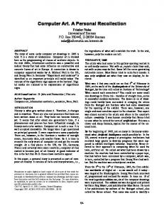
strategies for cochlear implants in real-time must perform several functions to convert sound into electrical stimulation. First, a microphone is used to convert an acoustic sound wave into an electrical representation. Second, in modern multi-channel speech processors, this analog representation is converted into digital samples. Third, the speech processor mathematically manipulates the digital samples according to the specified speech processing strategy. In general, these strategies use filter banks, envelope detectors, and additional steps to determine the sequence of pulses to be sent to the electrodes implanted in the cochlea. Fourth, the stimulation parameters (electrode, stimulus amplitude and stimulus duration) are encoded and transmitted via a radio frequency (RF) link to a device implanted beneath the subject’s skin. The implanted device, referred to as a receiver/stimulator, decodes the RF information and finally directs the delivery of the electrical stimulus to the implanted electrodes. The research platform described here performs all the functions that are normally performed by the external speech processor, the four steps outlined above, giving the researcher complete control. We anticipate that the processor that we designed and built can be adapted for use with any cochlear implant available in the market. While the bulk of speech processing and subjectspecific tailoring can be performed on a personal computer, a separate “driver” is needed to handle communication with specific CI devices. We have implemented such a driver for the Nucleus 22 CI, and plan to implement other drivers for the Nucleus 24, Clarion, and MedEl CI’s. One function performed by the driver sets the stimulation rate: the rate at which stimulation pulses will be directed to the electrodes in the implanted device. These are square biphasic pulses, with each phase having equal duration and opposite amplitude. Another function determines the inter-pulse interval: the delay between the positive going and negative going portions of the biphasic stimulus pulse. A third function directs a stimulation pulse at a given stimulation level to a specific electrode. The fourth, and last function, facilitates timing between the PC and the DSP driver by allowing the DSP to relay buffer status back to the PC. By using off-the-shelf components to the greatest extent possible, we have attempted to simplify the construction of this driver. With the exception of an RF pulse generator, the driver is implemented completely in software running on off-the-shelf components. II. MATERIALS Figure 1 depicts a simplified block diagram of the hardware used to implement the PC processor. There are two main components: the host PC, and the driver that allows the PC to communicate with the CI receiver/stimulator. The host PC was a DELL Inspiron 3500 laptop equipped with an Intel 350 MHz PII processor running Windows 98. It had 64 megabytes of RAM and a 4.5 gigabyte hard drive. In preliminary work the Sound Blaster Live! Value (Model SB4670) was used for sound capture and playback. These specifications are typical of generic PCs available at the time of this writing. This particular PC had more than enough power to implement the signal processing described here. An
updated version of the interface used a dedicated analog to digital board instead of the Sound Blaster board (Computer Boards PCM-DAS16D/16). The second hardware component, the driver, consists of a Motorola DSP56309EVM evaluation module. This digital signal processor (DSP) was only used to drive an RF pulse generator according to the communication protocol required by the Nucleus 22 receiver/stimulator. Thus, all the speech processing was done by the Intel processor in the laptop computer, and the DSP was only used to deliver the stimulation pulses to the cochlear implant. There are two communication lines between the PC and the DSP. The first is a serial cable between a PC COM port and the JTAG/OnCE port on the DSP. This connection is only needed during DSP program upload and initiation. Real-time communication, however, is maintained through the second connection, a Domain Technologies, Inc. Host Interface Adapter (DSP563xxEVM Host Port Interface Type B). This adapter allows fast bi-directional communication via the host PC’s printer port. This implementation uses the PC’s LPT1 port configured in EPP mode at address 0x378.
DSP
Parallel/ Serial Laptop PC
RF GEN. Implant Specific Driver
Receiver/ Stimulator
Figure 1. A microphone is connected to the PC via the sound card. The PC performs all A/D conversions and signal processing routines, leaving the implant-specific driver to generate the radio frequency (RF) pulses transferred to the receiver/stimulator. The implantspecific driver is initialized via the PC’s serial port. After initialization, commands that set the stimulation rate, inter pulse interval, and stimulation parameters are sent via the PC’s parallel port. Several software packages were used to implement the PC portion of the processor. The Microsoft Visual C++ V.6.0 compiler was used in conjunction with the runtime version of the Microsoft DirectX 7.1 software development kit to interface to the sound card and to implement all of the speech processing algorithms. In addition, Matlab version 5.2.1 was used to calculate filter parameters for the digital filters. Other software packages were used to develop, debug and load the driver software on the DSP. Domain Technologies, Inc. EVM563xx version 3.0 software was used to load the program that implements the driver on the DSP. The driver program code was written in assembly language and was compiled using the Motorola DSP56300 Assembler Version 6.2.0 that was provided with the DSP. PC side communications to the host port adapter on the DSP were implemented using the interface functions printed in the DSP563xxEVM Host Interface Adapter Reference Manual. No additional drivers were used for this purpose.
III. METHODS The PC processor consists of two main functional components: the PC running the speech processing software, and the driver that enables communication with the receiver/stimulator. The PC processor was designed so that it would not be a limiting factor in performance. For example, the maximum number of stimulation pulses delivered to the cochlear implant per unit time is determined by the electrical characteristics of the implanted receiver and the code used for RF transmission. The PC processor can deliver more stimulation pulses per unit time than the Nucleus-22 implanted receiver can handle, and this is also true for other CI models. The software used to implement the speech processing strategies will be described first. Each step in the signal processing pathway will be discussed in order from input to output. Following the description of the PC side algorithms, the functionality of the implant specific interface will be outlined. A configuration file was used to allow the experimenter to specify subject-specific parameters to be loaded at runtime. These parameters direct the modification of the speech information as it flows from input to output.
1 Preemphasis
AGC/ DRC
2 T
C
m
Filter Bank
H.W. Rectify
LPF Env. Detect
Channel Acoustic to Select/ Electric Order Mapping
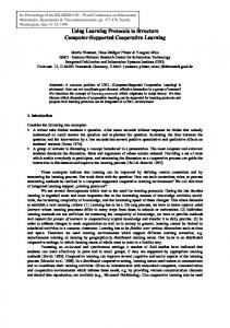
Figure 2. Signal Processing diagram. Data are sampled at 22050 Hz and 16 bits of resolution, and converted to single precision floating point. Preemphasis and automatic gain control/dynamic range compression (AGC/DRC), are then performed. Bandpass filtering and strategy-specific channel selection follow. The resulting channel envelopes are then logarithmically scaled and mapped to the subjects’s threshold and maximum comfortable stimulation levels. A. PC BASED SPEECH PROCESSING ALGORITHM It is impossible to anticipate the functionality required for all signal processing experiments, so only a basic system will be presented here. However, the steps described here are used in many speech processing algorithms. The signal processing performed with this platform is summarized in Figure 2. Processing begins by sampling incoming sound and converting it from integer to
single precision floating point. The use of floating point arithmetic simplifies the task of algorithm development by reducing the likelihood that unacceptably large or unacceptably small numbers will be generated during the process. Preemphasis is performed using a single tap Butterworth filter with Fc = 1200 Hz. This filter tends to decrease the prominence of the low frequency components of the incoming signal and has been implemented in most signal processing strategies for use in cochlear implants. (Eddington, 1998; Shannon, 1999). The next step is to perform automatic gain control/dynamic range compression (AGC/DRC). The algorithm used here is based heavily on earlier work by Eddington et al. (1993). This step normalizes the overall volume of the incoming signal by using three parameters: attack time, release time, and a dynamic range compression (DRC) table, and three variables: the current sample, the current envelope, and the previous envelope. First, an initial estimate of the envelope of the incoming signal is made based on a full wave rectified version of the incoming signal. The gain applied to the signal is then adjusted based on the previous estimate of the envelope and the current rectified signal as follows. When the rectified signal is greater than the previous envelope estimate, the gain is changed using a time constant equal to the attack time. When the rectified signal is smaller than the previous envelope estimate, the gain is changed using a time constant equal to the release time. The selected gain is such that the steady state transfer function of the AGC/DRC block follows the piecewise linear function described in the DRC table. A filter bank with m channels is next used to divide the incoming signal into its corresponding frequency components. These filters are four-tap infinite impulse response (IIR) filters implemented in a single direct form II stage for simplicity. In practice, different numbers of taps and filter implementations can be used, including FIR filter implementations. The characteristics of the filters are specified by the filter coefficients in the configuration file that is loaded at runtime. Once filtered, the resulting signal is half-wave rectified and subsequently low-pass filtered using a two tap IIR filter implemented in a single direct form II stage. The processing steps employed up to this point are identical for the two stimulation strategies we have implemented: CIS (continuous interleaved sampling, see Wilson et al., 1991) and n-of-m. These two stimulation strategies are the most commonly used in cochlear implants at present. At this point, the processor has created m channels of streaming data (up to 20 in this particular implementation) that can now be used to direct electrode stimulation. The following step of channel selection, however, is dependent upon which signal processing strategy is desired. CIS sequentially stimulates every available channel in the cochlear implant during every stimulation cycle. The amplitude at which each channel is stimulated is determined by the energy in the corresponding bandpass filter (Wilson, 1991). This means that each channel is stimulated once during each stimulation cycle.
In contrast, when n-of-m is selected only a subset of channels, those with the most energy in the corresponding bandpass filters, are stimulated during each stimulation cycle. Stimulation cycles typically last from 0.5 ms to 4 ms. The last step in the PC portion of signal processing maps the amplitude of the channel selected during the channel selection stage to an appropriate simulation level. Several subject-specific parameters are loaded during program initiation. For each channel, these parameters specify the electrode, mode, T level (the stimulation level that causes a barely perceptible sound in the corresponding channel), C level (the maximum stimulation level that is comfortable in the corresponding channel), acoustic minimum, and finally an acoustic maximum. The electrode simply refers to the actual electrode on the implanted receiver/stimulator. The mode refers to the way in which the electrodes are referenced. Each channel uses two electrodes, one positive and one negative. The mode determines which electrodes will be paired in a given channel. For example, stimulation using electrode 2 and a mode of 1 would specify electrode 2 as the positive electrode and electrode 3 and the negative electrode. Similarly, stimulation using electrode 2 and a mode of 2 would specify electrode 2 as the positive electrode and electrode 4 and the negative electrode. The remaining modes follow in this pattern. For each channel, the acoustic minimum specifies in dB, 20*log(filteroutput), the level of the low pass filtered envelope that will result in electrical stimulation at the T level. In other words, this is the acoustic level that is mapped to the corresponding perceptual threshold. The acoustic maximum specifies the acoustic level which will cause stimulation at the C level. An additional parameter modifies the shape of the acousticto-electrical mapping function. Stimulation above the C level is prevented, but stimulation at subthreshold levels is used to maintain power to the implant. Both the T and C levels are specified in clinical units which are a quasilogarithmic stimulus scale used in the Nucleus 22 device. Several real-time controls are also available to the experimenter. These controls are accessed through the keyboard, and allow the modification of overall loudness, sensitivity, and both the electrical and acoustic dynamic ranges. The resulting changes to the stimulation parameters are displayed on the computer monitor. Parameter changes made at runtime are not recorded in the configuration file. In any real-time signal processing system, timing is of great importance. It should be noted that the first sound card and drivers used in this implementation (Sound Blaster) introduced a fixed delay of approximately 70 ms. This meant that stimulation pulses resulting from speech take approximately 70 ms to be observed in the electrical stimulation pattern. Clearly, this is not an appreciable delay for auditory-only testing. For testing in audiovisual conditions, however, some listeners may notice a slight asynchrony between visual and auditory speech cues when conversing with others. This asynchrony was particularly apparent to the CI users when listening to their own speech. Recently we have reduced this delay to approximately 15-20 ms using a dedicated A/D data acquisition board in the PCMCIA port of the laptop computer.
B. IMPLANT SPECIFIC DRIVER After the speech processing algorithms implemented on the PC have determined the appropriate sequence of electrodes and stimulation levels to use, the signal is then sent via the parallel port, LPT1, to the implant-specific driver using four general purpose functions. The driver consists of three components: a communications driver (Domain Technologies, Inc. type B interface), a DSP (Motorola DSP56309EVM), and a custom built radio RF pulse generator. The communications driver uses two communication lines between PC and the DSP. The first, a serial port, is used by the DSP development software to download the driver program from the PC to the DSP and then to direct it to run. Once these two steps are accomplished, the second type B interface, provides a high speed connection between the PC and the DSP. The DSP 56309EVM is directed by the PC to perform four basic driver functions. Several aspects of this implementation must be considered. First, the implantspecific driver implemented on the DSP serves as a first-infirst-out (FIFO) buffer. This enables the maintenance of a continuous stream of information to the receiver/stimulator even when the PC is busy. This FIFO ensures that commands are executed in the order in which they were sent. It is also important to note that once the driver is running, stimulation pulses will be continuously sent at the specified rate of stimulation. If the PC falls behind the FIFO in directing stimulation pulses, the driver will maintain power to the implant by directing the receiver/stimulator to send a minimum amplitude, minimum phase stimulation pulse on electrode 2 with mode 1. This pulse is inaudible to the CI user and is used only to keep the implant working. Conversely, if the PC continues to direct stimulation or parameter changes when the FIFO is full, the instructions are discarded. A function that returns the status of the FIFO buffer was implemented to avoid these situations. The four functions that were implemented allow a variety of stimulation strategies to be implemented in real time. The first function allows the PC to instruct the receiver/stimulator to send a stimulation pulse. It allows the user to specify the electrode, mode, amplitude and phase duration of the desired stimulation pulse. The second function sets the total stimulation rate in pulses per second. This function determines the rate at which the receiver/stimulator will ultimately be directed to deliver stimulation pulses. The third function allows the user to set the length of time between the positive and negative going portions of the biphasic stimulation pulse. This time is called the inter phase interval. The fourth and last function returns the number of locations available in the internal FIFO buffer. When directed by the PC, the driver will immediately report on the FIFO status. This command is not processed through the FIFO like the other three functions. When streaming from a data file, this function can be used to determine how many pulses can be sent to the FIFO before it overflows. Instructions sent to the FIFO when it is full are discarded.
C. RADIO FREQUENCY (RF) GENERATOR The DSP portion of the driver encodes the electrode, mode, amplitude, and phase information in a series of 2.5 MHz pulses that are sent to the receiver stimulator. Before sending these pulses, however, an RF generator must amplify the signal so that it can be received by the receiver/stimulator. An example of such a generator appears in Figure 4. This circuit is based on a simple damped oscillator and is driven directly through a serial communications port on the DSP. A TTL clock generator controls the frequency of the RF signal being sent through the headpiece to the receiver/stimulator. The TTL clock is also used as an external bit-rate clock for the serial port on the DSP. The RF generator uses the TX signal from the DSP’s ESSI0 port to modulate the amplitude of a 2.5 MHz carrier. The output is sent to the headpiece. Alternative clock rates, for implants other than the Nucleus 22 can be obtained by simply changing the TTL clock in the RF generator and ensuring that the desired output waveform is achieved. The DSP clock and RF generator clock are independent.
users’ performance using their own speech processor was similar to that obtained with the PC processor programmed with similar settings. Tests in this battery included CNC word lists, a 50 item monosyllabic open-set word identification task (Peterson & Lehiste, 1962), and 16 consonants from the Iowa Consonant Identification Task (female speaker) (Tyler et al., 1987). Both of these tests used natural speech and were presented in an auditory only condition. The consonant identification task uses 16 consonants in an /a/consonant/a/ format. For example, the consonant m would be presented as ama. Each consonant was presented six times under each processor condition. Each subject was also administered two CNC word lists with their own commercial processor, and with the PC based processor. Prior to the testing session, listeners were allowed to acclimate to the PC processor by conversing with the experimenter and listening to their own speech production for about five to ten minutes. For this testing, the PC processor was configured to approximate the signal processing characteristics of their own commercial processor. IV. RESULTS Performance for the PC processor was roughly similar to performance with the subject’s own device. Figure 5A and 5B show these results. A one- way ANOVA using the processor type as a within subjects variable did not show any significant effects of processor type for the group as a whole. That is, for these three subjects, the PC based processor and the commercial speech processor did not yield any performance differences for the group. V. DISCUSSION/CONCLUSION
Figure 4. Circuit diagram of the radiofrequency (RF) generator. Variable resistors are used to adjust the output voltage and waveform characteristics. D. SPEECH PERCEPTION TESTING We have conducted a pilot study to test the performance of the PC processor. The speech perception scores from the three CI listeners using the PC processor (nof-m strategy) was compared to their scores obtained with their own commercial speech processors. Although the strategy implemented in the PC processor, described above, and that implemented in the commercial speech processor were not identical (because not all the details of the commercial speech processing are in the public domain), they were quite similar. Each listener completed a battery of speech perception tests with the goal of showing that CI
In summary, the PC based speech processor described here represents a new approach to the development of the next generation cochlear implants. This system may allow researchers to implement new speech processing algorithms much more easily at a fraction of the cost and time that is currently required for this type of research and development, because the signal processing can be done using a language such as C++ running on a PC, instead of using DSP tools. Preliminary testing of this system with three users of the Nucleus 22 cochlear implant shows that the PC processor functions within specifications. VI. FUTURE DIRECTIONS Work is currently underway in our laboratory to interface the PC based signal processing platform described here to all the CI and auditory brainstem implants (ABIs) currently in use or in clinical FDA trials in the US. But more importantly, the next step in our development program will be to test a variety of speech processing strategies that may help CI users (and ABI users) to perceive, recognize, and understand speech better. New speech processing strategies developed using this platform, the PC processor, may help specify and develop new neural prostheses that will provide
higher levels of performance over a wide range of listening conditions and in a wide range of listening environments.
Consonant Identification 100 90
Percent Correct
80
A
Commercial Processor PC Processor
70 60 50 40 30 20 10 0
CI1
CI2
CI3
Subject Word Identification 100 90
Percent Correct
80
B
Commercial Processor PC Processor
70 60 50 40 30 20 10 0
CI1
CI2
CI3
Subject
Figure 5A, B. Consonant and Word identification scores for listeners using their own commercial speech processor (black bars) and with the PC based speech processor (gray bars).
VII. REFERENCES Dorman, M.F., Loizou, P.C., & Rainey, D. (1997). Simulating the effect of cochlear-implant electrode insertion depth on speech understanding. Journal of the Acoustical Society of America. 102, 2993-2996. Eddington, D.K. (1980). Speech discrimination in deaf subjects with cochlear implants. Journal of the Acoustical Society of America, 68(3), 885-891. Eddington, D.K., Rabinowitz, W.M., Svirsky, M.A. & Tierney, J. (1993). Speech Processors for Auditory Prostheses (Fourth quarterly progress report, NIH Contract N01-DC-2-2402) National Institutes of Health, Bethesda, MD: Neural prostheses program.
Eddington, D.K., Garcia, N., Noel, V., Tierney, J., & Whearty, M. (1998). Speech Processors for Auditory Prostheses (Final report, NIH project N01-DC-6-2100). National Institutes of Health, Bethesda, MD: Neural prostheses program. Fu, Q.J., & Shannon, R.V. (1999). Effects of electrode configuration and frequency allocation on vowel recognition with the Nucleus-22 cochlear implant. Ear & Hearing. 20(4), 332-44. Kiefer, J., Muller, J., Pfenningdorff, T., Schon, F., Helms, J., von Ilberg, C., Baumgartner, W., Gstottner, W., Ehrenberger, K., Arnold, W., Stephan, K., Thumfart, W., & Baur, S. (1997). Speech understanding in quiet and in noise with the CIS speech-coding strategy (MED EL Combi-40) compared to the MPEAK and SPEAK strategies (Nucleus). Advances in Oto-Rhino-Laryngology, 52, 286-290. Lawson, D.T., Wilson, B.S., Zerbi, M., Finley, C.C. (1996). Speech processors for auditory prostheses (Third quarterly progress report, NIH prject N01-DC-5-2103). National Institutes of Health, Bethesda, MD: Neural prostheses program. Loeb, G.E., & Kessler, D.K. (1995). Speech recognition performance over time with the Clarion cochlear prosthesis. Annals of Otology, Rhinology, & Laryngology, 166, (Suppl.), 290-292. Peterson, G., & Lehiste, I., (1962). Revised CNC lists for auditory tests. Journal of Speech and Hearing Disorders, 27, 62-70. Rosen, S., Faulkner, A., Wildinson, L. (1999). Adaptation by normal listeners to upward spectral shifts of speech: Implications for cochlear implants. Journal of the Acoustical Society of America, 106, 3629-3636. Shannon, R.V., Zeng, F.G., Wygonski, J. (1998) Speech recognition with altered spectral distribution of envelope cues. Journal of the Acoustical Society of America, 104, 2467-2476. Shannon, R.V., Zeng, F.G., Kamath, V., Wygonski, J., and Ekelid, M. (1995). Speech recognition with primarily temporal cues. Science 270, 303-304. Staller, S., Menapace, C., Domico, E., Mills, D., Dowell, R.C., Geers, A., Pijl, S., Hasenstab, S., Justus, M., Bruelli, T., Borton, A.A., & Lemay, M. (1997). Speech perception abilities of adult and pediatric Nucleus implant recipients using spectral peak (SPEAK) coding strategy. Otolaryngology-Head & Neck Surgery, 117, 236-242. Tyler, R. S., Preece, J. P., & Lowder, M. W. (1987). The Iowa audiovisual speech perception laser video disc. Laser Videodisc and Laboratory Report, University of Iowa at Iowa City, Department of Otolaryngology – Head and Neck Surgery. Wilson, B.S., Finley, C.C., Lawson, D.T., Wolford, R.D., Eddington, D.K., & Rabinowitz, W.M. (1991). Better speech recognition with cochlear implants. Natur., 352(6332), 236-238.