Sep 14, 2001 - of control values where the update times must have low jitter. ..... ments for the upgrade were kept low. Mapping all .... IOS Press, 1997. [Wol94].
Research Report 2/2001 Published in: Proceedings of the The 27th Annual Conference of the IEEE Industrial Electronics Society Hyatt Regency Tech Center, Denver, Colorado, USA Nov 29 to Dec 2, 2001
Using Sensor Fusion in a Time-Triggered Network W. Elmenreich and S. Pitzek Institut f¨ ur Technische Informatik TU Vienna, Austria Tel: +43 (1) 58801-18234 {wil,pitzek}@vmars.tuwien.ac.at September 14, 2001
Abstract
a particular property differ in their measuring methods, resolution, measuring range, conversion time and reliability. Each single sensor is only capable of viewing the part of the environment that we are interested in through a rather narrow window of time and space. To overcome those limitations of single sensors, methods for the combination of data from different sensors via sensor fusion algorithms have been developed.
Smart transducer technologies support the composability, configurability and maintainability of sensor networks. Sensor fusion techniques on the other hand offer a lot of advantages for systems that interact with their environment via a set of sensors. The combination of both leads to an effective system regarding cost, robustness, decomposability and maintainability. This paper examines architecture requirements that incorporate smart transducer networks with sensor fusion processing and a hardware-independent application interface. These requirements are compared to the properties of the Time-Triggered Architecture and the TTP/A protocol. A mobile robot controlled by a Time-Triggered Protocol network shows the presented ideas.
Typical data fusion applications contain a network of distributed sensors, intelligence to process the sensor data, e. g. by sensor fusion algorithms, a control program, that derives the output value based on these sensor data, and actuators that carry out these actions. Such an application is a complex system, difficult to build, to verify, to repair, and to change. A good method to reduce the complexity of a system is to “divide and conquer”. I. e., the system is partitioned into interacting subsystems. Partitioning can be applied to hard- and software [Wol94]. To put these subsystems to work, they must communicate in terms of energy, matter, and information. Design of this communication system is a critical task and if the composition of the subsystems fails because of interface mismatches, the whole systems refuses to work even if each particular subsystems was proven to be functionally correct. Thus, if we want to partition a complex system, we have to care-
Keywords: multi-sensor, sensor fusion, realtime systems, time-triggered, fusion architecture, interface.
1
Introduction
Intelligent sensor processing aids in the development of systems that “see” and “comprehend” their environment using computational methods to get a picture of the environment using the data collected by sensors. Sensors measuring 1
fully select the borderlines between subsystems. These borderlines have to be well-defined interfaces to enable composability. In many cases a subsystem is already given as a legacy system. If the legacy system does not provide an appropriate interface to the other subsystems with which it is interacting, the introduction of an extra component, an interface system, may resolve this mismatch. In this paper we examine the partitioning of a data fusion system into three levels. An according architectural model has already been presented in [EP01]. For the given model we will examine the requirements and benefits for such a three-level architecture. It will be shown that beside the sensor fusion benefits listed in the work of Bosse [BRG96] and Grossmann [Gro98], sensor fusion also has a positive effect on interface design between sensors and application. An investigation of a time-triggered communication protocol will show that the protocol is apt to implement a distributed sensor fusion network for mobile robots. The remainder of the paper is structured as follows: Section 2 describes an architectural model for sensor fusion applications and arguments for the three-level partitioning. Section 3 deals with the requirements for system architecture and communication. Section 4 introduces the principles of operation of the TTP/A protocol and compares the requirements of Section 3 to the properties of the TTP/A protocol. Section 5 describes a case study implementation of a mobile robot based on a TTP/A network that has been implemented following this three-level architecture and Section 6 discusses the results received from this case study. Finally, the basic ideas of this paper are summarized in Section 7.
2
Environment
�
Sensors �
Actuators
Smart Transducer Interface
�
�
�
Sensor Fusion Fault Tol . Layer
Fault Tolerance Layer
Fault Tolerant Image of the Environment �
�
�
Figure 1: Model
Control Decision User Commands
Smart Transducer Interface �
�
Node Level
Cluster Level
Fault Tolerant Actuator Interface
Control Application �
Lvl .
Control Loop in the Three-Level
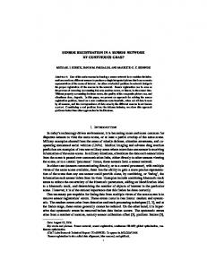
work we partition the system into three levels: The first level is the node level and consists of nodes with transducers (sensors or actuators) equipped with a smart transducer interface. The second level is the cluster level that integrates the transducer nodes into a network, performs sensor fusion and presents the results to the control application level. The cluster level optionally contains a fault tolerance layer handling node failures. At the third level, the control application level, decisions about control values are made and, if necessary, user interaction is handled. Between these levels well-defined interfaces are introduced. A smart transducer interface handles data flow from node to cluster level. The cluster level presents its results to the environment in the form of a fault tolerant image of the environment. Fig. 1 shows a control loop modelled with this three-level design approach. The breakdown into these three levels is justified by different functions each level has to fulfill, different data types that are used in each level and different teams implementing and supporting the subsystems. It might be advantageous in some cases to im-
Architectural Model
We assume a three-level design approach for the system architecture. For the TTP/A protocol the idea of a two-level design approach has already been proposed in [PAG+ 00]. In this 2
plement the levels in different hardware parts. However, the presented conceptual model does not depend on the employment of distinct hardware parts. The motivation for the introduction of these levels is a reduction of system complexity at cluster and control application level and the possibility of software reuse. Furthermore the standardization of the smart transducer interface leads to benefits in the area of configuration, diagnosis and maintenance.
2.1
sheet as it is proposed in the IEEE 1451 Standard [Ecc98]. • The internal complexity of the smartsensor hardware and software and internal failure modes can be hidden from the user by well-designed fully specified smart sensor interfaces that provide just those services that the user is interested in. • It is possible to locally monitor the operation of the sensing element via the network, thus simplifying diagnosis.
Node Level
Each sensor can be seen as a window showing a small part of the environment. It is the task of the node level to provide each window view. The node level interacts physically with the environment by performing measurements with sensors or actions with actuators. To support maximum modularity, the nodes are built as smart transducers. A smart transducer is the integration of an analog or digital sensor or actuator element and a local microcontroller that contains the interface circuitry, a processor, memory and a network controller in a single unit. The smart sensor transforms the raw sensor signal to a standardized digital representation, checks and calibrates the signal, and transmits this digital signal via a standardized communication protocol to its users [KHE00]. The smart sensor technology offers a number of advantages from the point of view of technology, cost and complexity management [Kop99]:
2.2
Cluster Level
The cluster level contains the hardware and software that act as a glue between transducers and control application. It integrates the measurements from the sensors into a unified view of the environment into an environment image. If necessary, this image is made tolerant to incomplete, erroneous or missing measurements by implementing sensor fusion algorithms and a fault tolerance layer. The properties of this image, e. g. content, resolution, update timing, and data structure, depend on the control application at the next level. A change in the node configuration results in an adoption of the cluster level software. The cluster level contains software elements like communication schedules, fusion and voting algorithms and hardware like bus lines with system nodes controlling the communication and performing fusion and voting.
• Electrically weak non-linear sensor signals can be conditioned, calibrated and transformed into digital form on a single silicon die without any noise pickup from long external signal transmission lines [DW98].
2.3
Control Application Level
The control application programmer’s interest focuses on the environment image, while the responsibility for its temporal accuracy and correctness is delegated to the designers of the sensor fusion and fault tolerance layer. The control application level contains the intelligence to make decisions based on the environment image. The specification of the image
• The smart sensor contains a well-specified digital communication interface to a sensor bus, offering “plug-and-play” capability if the sensor contains a reference to its documentation in form of an electronic data 3
derives from the control application level. Because the application does not directly rely on the sensor measurements, the same control program can be used with different sensor configurations. The user interface is also settled in the control application level.
3
A light sensor can provide different outputs, an analogue output corresponding to the amount of light the sensor is exposed to, and a binary output corresponding to the values “light” and “dark” compared to an internal threshold value that can be configured over the configuration interface.
Architectural Requirements
Configurability To achieve the above mentioned flexibility, means for in-system configuration and reconfiguration of transducers have to be provided by the sensor and its working environment.
Following our three-level model presented in Section 2 we worked out requirements for each level that have to be met to provide an efficient real-time system according to the assumed architecture.
3.1
Plug-and-play capabilities For the automatical integration of additional sensors to a running cluster, some kind of hard-coded reference to its specification has to be integrated in the sensor.
Node Level
To enable maintainance, monitoring and configuration of a real-time system, the smart transducer nodes at node level should support a unique interface with the following features:
3.2
Cluster Level
Sensor fusion processing and fault tolerance voting places some special requirements on the underlying sensor framework concerning timing behaviour and structure of the sensor data delivered by the sensor layer:
Composability A smart sensor should be independent of all other sensors in its environment. Communication is only performed via a specified interface thus liberating sensor manufacturers from interoperability issues between sensors, naming inconsistencies and the network topology of the total system.
Fusing Real-Time Values To find an agreed value when two or more real-time values are fused, the instant of the measurement must be transmitted with the measured value. Control of Real-Time Objects Most control algorithms need periodical updates of control values where the update times must have low jitter. Also the time span from performing measurements on the controlled object until the execution of the control decision on this object must not exceed a certain time limit.
Standardized Sensor Data To facilitate further processing at cluster level the sensor data has to be preprocessed in the node and transformed into a standardized format. Flexibility In order to support the needs of different applications some smart transducers must be capable of operating in different modes. For example:
Fault-Tolerance To implement faulttolerance by active redundancy the data sources have to be replica deterministic [Sch90]. If the replicated nodes proceed along different computational trajectories, then, the switchover from one result of a
A signal smoothing in the signal processing unit of a smart sensor node will do fine in many applications, but must be bypassed if the dynamical behavior of the signal is of greater concern than the reduction of noise. 4
replica to the result of another will upset the controller and can lead to a serious error [Kop97].
3.3
communication is organized into rounds. Bus access conflicts are avoided by a strict TDMA schedule for each round. A round consists of several slots. A slot is a unit for transmission of one byte of data. Data bytes are transmitted in a standard UART format. Each communication round is started by the master with a so-called fireworks byte. The fireworks byte defines the type of round. A multipartner round (see Fig. 2) consists of a configuration dependent number of slots and an assigned sender node for each slot. The configuration of a round is defined in the RODL (ROund Descriptor List). The RODL assigns a writing node and several receiving nodes for each time slot. RODLs must be configured in the slave nodes prior to the execution of the corresponding multipartner round. For unique addressing of the slave’s internals all relevant data of a TTP/A node like round definitions, application specific parameters and I/O properties are organized into a structure called Interface File System (IFS) [KHE00]. The IFS is structured in a record-oriented format. Each record is addressable separately by master/slave rounds. A master/slave round establishes a connection between the master and a slave for reading/writing monitoring or configuration data, e. g. the RODL information. The action and the address in the IFS of a master/slave round are encoded in three parameter bytes sent after the fireworks byte. In a further part of a master/slave round the addressed data bytes are transmitted between master and slave. A master/slave round has a fixed layout that addresses and transmits a particular record in the slave’s IFS.
Control Application Level
The control application level comprises the part of the real-time system that contains the application-specific software. While the control application level imposes timing and communication requirements on the underlying network, the control software ought to be widely independent from the employed transducers and the signal processing algorithms among them. Two requirements emerge from the view of the control application level: Interface to cluster level The data structure of the real world image has to be chosen in a way, that the sensor fusion layer is capable of mapping all possible sensor data into this structure. On the other hand, the data structure needs to be small to be communicated efficiently over the network. Generic Coding To support software reuse of the control application code in case of modification or redesign of sensor hardware or topology, or changes in the processing software the control program must be implemented in a flexible, generic way.
4
System Architecture
For a case study we have chosen the TimeTriggered Architecture [SHS+ 97, Kop98] and the TTP/A Protocol [Kop00] to build a realtime system according to the architecture described in Section 2.
4.1
Principles of Operation
Slot 0
TTP/A is a master-slave protocol and a member of the time-triggered protocol class. It is possible to address up to 254 nodes on a bus. One node is the active master. This master provides the time base for the slave nodes. The
FB
Slot 1
Slot 2
Slot 3
DataByte DataByte DataByte
Slot n DataByte
Time FB Fireworks Byte, sent by master DataByte sent either by master or slave
Figure 2: A TTP/A Multipartner Round 5
All nodes contain several files that can be accessed via the TTP/A protocol in a unified manner. The minimal set-up for a smart transducer is:
TTP/A is intended to connect smart transducers to a real-time system [Kop00]. It provides communication with deterministic timing behavior and low jitter. Nodes within a TTP/A cluster are independent of each other. Each node knows a priori when to send or receive, there are no interdependencies between different nodes. Transmission times are based on an absolute synchronized time, even when imprecise clock oscillators are used in the the slave nodes. Therefore, communication in TTP/A is replica deterministic even when employing clocks with immoderate drift rates. Because of the static schedule in the RODLs, it is possible to determine exactly wether deadlines are met with a given bus capacity. Clock synchronization is inherent in TTP/A, thus generating precise time-stamps and acquiring transmission times of data is straightforward without the introduction of additional mechanisms. The TTP protocol family supports a twolevel design approach. On node level, the smart transducers are implemented by component suppliers, while on cluster level a system integrator defines the subsystem functions and specifies the communication interfaces in the value and time domains [PAG+ 00]. This design approach can easily be aligned with the three-level model discussed in section 3 by adding a control application level on top of the cluster level. The TTP/A protocol provides dedicated interfaces for the (in-system) reconfiguration of nodes in a cluster, which increases the flexibility of the total system.
Round Descriptor List (RODL) File: Each node contains at least one and up to six RODL files that contain TDMA schedules for the TTP/A multipartner rounds. TTP/A Configuration File: This file contains at least an 8 bit alias which is the slave’s name when it is addressed via master/slave rounds. Documentation File: This file contains a 64 bit node identifier. The node identifier is a world-wide unique number for each node that is assigned invariably when the node is manufactured. Optionally this documentation file contains the ASCII text of an uniform resource locator (URL) pointing to a file containing the node’s data sheet. Documentation files are read-only from the master’s viewpoint. At startup the master uses master/slave (MS) rounds for determining the types of the connected nodes and configuring them. The multipartner (MP) round is intended to establish a periodical, predictable and efficient real-time communication. To support a diagnosis and maintenance access concurrent to the real-time traffic it is recommended to schedule multipartner rounds and master/slave rounds interleaved (see Fig. 3).
4.2
Suitability of TTP/A for a realtime sensor fusion environment
4.3
Because of the low-cost nature of our examined systems there are certain restrictions which have to be taken into account. The communication in TTP/A is optimized for short messages. When working with relatively simple sensors, messages are likely to be short. But some sensor-fusion applications
In this section we examine how TTP/A fulfills the requirements of the three-level model.
MP round
MS round
MP round
MS round
Restrictions
MP round
Time
Figure 3: Recommended TTP/A Schedule 6
need complex data-structures to be transmitted. This especially holds true for data transmitted between the sensor fusion and the control application level, where, as stated earlier, applications should be provided with enhanced abstract data requiring complex data structures. In applications that use multi-dimensional data structures a communication network designed for transducer data can become the bottleneck. A solution to this problem can be an enhancement of the transmission speed (TTP/A supports transmission speeds up to several MBit/s) or an alternative realization of the interface between cluster level and control application level, e. g. by a dual-ported RAM. Connecting extra nodes to the network for performing the fusion algorithms leads to increased network traffic. Using a certain communication medium places an upper boundary to the number of nodes that can be served by the system. For example, single wire busses are restricted to several kBytes/s. Thus, not all sensor fusion algorithms can be implemented in a low-cost environment.
5
Obstacle Sensor Beams
Sensor Fusion
uncertainty region of single sensors Smart Car uncertainty region of joint sensors
Actuator
Application Real World Image
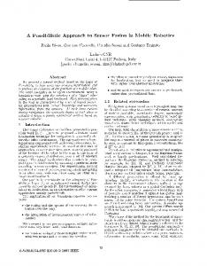
Figure 4: Smart Car The data stream provided by the distance sensors is taken over by the data processing node that fuses the perceptions from the distance sensors with a model of the robot’s environment. In this model the shapes of obstacles are stored and assigned with a probability value, that decreases with the progression of time and increases when the object is re-scanned. Fig. 4 depicts the scanning range of the distance sensors and the fusing of sensor data into a sensor grid [BK91]. Based on this grid the control application makes decisions about direction and speed of further movement. There are 16 slave nodes and one master node on the car. The navigation program and the sensor fusion program is hosted on a single node, so that the real world image has not to be transmitted over the network. Thus, the necessary bus speed was kept low (about 20 KBit/s) which made it possible to use a low-cost single-wire bus. Although the smart car is able to move autonomously through its environment, it is planned to apply an interface to a service point. As depicted in Fig. 5 the TTP/A master also maintains a monitoring interface to a service point. The dotted line marks a possible virtual connection from the service point to an arbitrary node. Because the service access usually is not
Case Study
To show the ideas described in Section 2 we developed a model car based on the architecture proposed in Section 4. The model comprises a mobile robot (“smart car”) equipped with a suit of pivoted distance sensors, an electric drive and a steering unit. Distance sensors, servo motors for sensor pivoting, driving and steering units are all separate TTP/A nodes. Each node is implemented on a low-cost microcontroller and equipped with a smart transducer interface [KHE00]. The network also contains a master node and a data processing node. The distance sensors are swivelled around by servo motors so that they are able to scan the area in front of the robot. The sensors generate a value that corresponds to the distance of the object they are aimed at. 7
the cluster. On TTP/A implementations for the Atmel AT90S microcontroller series the expense for the implementation of the interface file-system was rated. The implementation overhead for the filesystem implementation with master-slave access was about 0.6 kB ROM code. The protocol code itself took about 1.5 kB ROM code. Application code sizes ranged from several instructions in the headlight nodes up to 5 kB in the fusion node.
ServicePoint Configuration, Monitoring Diagnostic RS232 or Wireless Connection
�
TTP /A Slave
�
TTP /A Slave
�
TTP /A Slave
Service Interface TTP/A Master
TTP/A Bus �
TTP /A Slave
�
TTP /A Slave
Figure 5: Monitoring the Nodes from a Service Point
7
We presented an architectural model that supports a break down of a sensor fusion application into three levels, the node level, the cluster level, and the control application level. Communication between these levels is performed via an interface filesystem that provides welldefined interfaces. Sensor fusion techniques are used to establish a hardware-independent interface to the control application. The advantages of this approach rely on a reduction of system complexity at cluster and control application level and the possibility of software reuse. Furthermore the standardization of the smart transducer interface leads to benefits in the area of configuration, diagnosis and maintenance. We also designed and implemented this architecture in a case study. The case study proved the openness to changes or extensions of sensor nodes and modifications on the control program.
time critical it is possible to route this connection over different networks, e. g. the internet. It is planned to implement a wireless connection between the car and the service point.
6
Conclusion
Results
The interface file system worked well as smart transducer interface and made it possible to split and to implement the tasks of protocol and application concurrently. Later we decided to add automatic node recognition, a preliminary version of plug-andplay. The generic structure of the interface file system was easily adopted to this requirement. Because the infrastructure was already present with the interface file system, resource requirements for the upgrade were kept low. Mapping all relevant information into the interface file system created clean interfaces between the subsystems and enabled monitoring of these properties over master-slave rounds. However it takes two master-slave communications to retrieve a single record from a node. This speed was not sufficient to monitor fast changing values. Therefore an alternative monitoring approach was implemented that accesses the bus directly over an extra node (bus sniffer). Neither the master-slave monitoring approach nor the bus sniffer affect the timing behavior of
8
Acknowledgments
We would like to give special thanks to our colleague G¨ unther Bauer for constructive comments on earlier versions of this paper. This work was supported in part by the Austrian Ministry of Science, project TTSB and by the European IST project DSoS under contract No IST-1999-11585. 8
References [BK91]
[BRG96]
[Sch90]
J. Borenstein and Y. Koren. The vector field histogram - fast obstacle avoidance for mobile robots. IEEE Journal of Robotics and Automation, 7(3):278–288, June 1991.
[SHS+ 97] C. Scheidler, G. Heiner, R. Sasse, E. Fuchs, H. Kopetz, and C. Temple. Time-Triggered Architecture (TTA). Advances in Information Technologies: The Business Challenge, IOS Press, 1997.
E. Bosse, J. Roy, and D. Grenier. Data fusion concepts applied to a suite of dissimilar sensors. Canadian Conference on Electrical and Computer Engineering, 1996, 2:692–695, May 1996.
[DW98]
P. Dierauer and B. Woolever. Understanding smart devices. Industrial Computing, pages 47–50, 1998.
[Ecc98]
L. H. Eccles. A brief description of IEEE P1451.2. Sensors Expo, May 1998.
[EP01]
W. Elmenreich and S. Pitzek. The timetriggered sensor fusion model. Sept. 2001.
[Gro98]
P. Grossmann. Multisensor data fusion. The GEC journal of Technology, 15:27–37, 1998.
[KHE00]
H. Kopetz, M. Holzmann, and W. Elmenreich. A universal smart transducer interface: TTP/A. Proceedings of the 3rd International Symposium on Object-Oriented Real-Time Distributed Computing (ISORC), March 2000.
[Kop97]
H. Kopetz. Real-Time Systems, Design Principles for Distributed Embedded Applications. Kluwer Academic Publishers, Boston, Dordrecht, London, 1997.
[Kop98]
H. Kopetz. The time-triggered architecture. Proceedings of the 1st International Symposium on Object-Oriented Real-Time Distributed Computing (ISORC), pages 22–29, 1998.
[Kop99]
H. Kopetz. Do current technology trends enforce a paradigm shift in the industrial automation market? Closing Keynote at the 7th IEEE International Conference on Emerging Technologies and Factory Automation (ETFA 99), Barcelona, Spain, October 1999.
[Kop00]
H. Kopetz et al. Specification of the TTP/A protocol. Technical report, Technische Universit¨ at Wien, Institut f¨ ur Technische Informatik, March 2000. Available at http://www.ttpforum.org.
F. B. Schneider. Implementing fault-tolerant services using the state machine approach: A tutorial. ACM Computing Surveys, 22(4):299–319, 1990.
[Wol94]
[PAG+ 00] S. Poledna, H. Angelow, M. Gl¨ uck, M. Pisecky, I. Smaili, G. St¨ oger, C. Tanzer, and G. Kroiss. TTP two level design approach: Tool support for composable fault-tolerant real-time systems. SAE World Congress 2000, Detroit, Michigan, USA, March 2000.
9
W. H. Wolf. Hardware-software co-design of embedded systems. Proceedings of the IEEE, 82(7):967–989, July 1994.