THE ELEVENTH INTERNATIONAL MIDDLE EASTPOWER SYSTEMS CONFERENCE
(MEPCON'2oo6)
VERTICAL-AXIS WIND TURBINE MODELING AND PERFORMANCE WITH AXIAL-FLUX PERMANENT MAGNET SYNCHRONOUS GENERATOR FOR BATTERY CHARGING APPLICATIONS Ahmad M. Eid, Mazen Abdel-Salam and M. Tharwat Abdel-Rahman
Abstract- The modeling and simulation. of a I kW vertical-axis direct drive topology wind turbine are
implemented.
An axial nux permanent magnet
synchronous generator with multi-pole Is directly connected to the wind turbine shaft. The wind tllrbine system is controlled to operate at constant tip-speed ratio and hen~e maximizing the power extracted from the wind. For battery charging applications, a modified version of buck-boost DC-DC converter Is used to keep the output voltage constant at any wind speed. The proposed control method is simple and fast enough to track the optimal speed of the wind turbine.
I.
INTRODUCTION
Due to the increase of the environmental concern, the electrical power generation from renewable energy sources, such as wind, is increasing and adopted. Wind is suitable for either grid integration or as a stand-alone system used for remote areas for illuminating purposes or in charging battery systems. The rotatingspeed of the wind turbine is usually slow. Thus to reduce the generator size, the wind turbine is coupled to the generator through a gearbox which generates noise, increases total weight, needs regular maintenance and increaseslosses [1]. Most of wind turbines installed use one of three main types of electromechanical conversion system. Turbines with variable rotor speed are able to operate at constant tip-speed ratio, and therefore tend to have a higher energy than fixed speed machines. A squirrel-cage or doubly-fed induction-generator is used with a gear box system. The third type is called the 'direct drive wind turbine', because no gearbox is needed. A low-speed multi-pole synchronous ring generator with the same rotational speed as the wind turbine rotor is used to convertthe mechanical energy into electricity. The generator can have a wound rotor or a rotor
with permanent magnets. The stator is not coupled directly to the grid, but to a power electronics converter. This may consist of a back-to-beck voltage source converter or a diode rectifier with a single voltage source converter. The efficiency and reliability of the direct coupled permanent magnet synchronous generator (PMSG) is improved compared to the conventional'wind power generation system. Vertical-Axis Wind Turbine (VAWT) has some advantages' [2], as it does not need a tail or a yaw mechanism to point it into the wind. This simplifies the construction and thereby reducing cost. There is no loss of performance due to misalignment of the turbine axis with the wind direction as there is with horizontal axis wind turbines. For VAWT, the tower is not essential for the machine. In wind generation systems, the i~duction generator is popular [3-4] although it needs reactive power for magnetization,
particularly during start-up, which can cause voltage collapse after a fault on the grid [5]. Small wind turbines are suitable for battery charging because of its simplicity and can be distributed over a long distance [6]. In this paper, the modeling and simulation of a lkW VAWT are implementedusing PSIM6 software package. Transient and steady state simulations for the VAWT at different wind speed are explained. The VAWT is controlled to operate at maximum mechanical power output, thus extracting maximum power from the wind into electricity. The output voltage of the DC-DC converter is controlled to be constant at any wind speed for battery charging applications. For small wind speeds, the output voltage is boosted and for large wind speeds, the output voltage is bucked.
'A. M. Eid with Aswan Facultyof Engineering, Aswan, Egypt, TeVFax: +20974661397, email:
[email protected]. M. Abdel-Salam with Facultyof Engineering, Assiut,Egypt. M. Tharwatwith AswanFacultyof Engineering, Aswan,Egypt.
- 162-
II. VAWT SYSTEM MODELING
71lE ELEVENTH INTERNATIONAL MIDDLE EAST POWER SYSTEMS CONFERENCE
A.
Wind Turbine Aerodynamic Characteristics The converted electrical power from the wind . power depends on power coefficient Cp, the gearbox efficiency (if exist), the generator efficiency and power-electronic converter efficiency. The power coefficient Cp is limited to a maximum of 0.59 (Bitz limit) [7-8]. The following well-known algebraic equation gives the relation between the mechanical power captured from the wind by the wind turbine as a function ofthe wind speed [9-11]:
Pm=iPACp(A.)U~
(1)
where p is the air density (1.225Kglm\ A is the area covered by the wind turbine rotor (2.25m 2) , Uw is the wind speed (mls), Cp is the power coefficient of the wind turbine and A is the tip-speed ratio and is related to the rotor speed as:
A.= Q]m R
(MEPCON'2oo6j
As it can be seen from Fig. 2, that the power coefficient, Cp, has a maximum value at a certain tipspeed ratio which at the wind turbine is controlled to keep A at this value. The Cp->.. curve has a wide flat top characteristic, which insures better performance for the VAWT. The output mechanical power of the VAWT versus rotor speed while the speed of the wind is changing over wide range is shown in Fig. 3. If the generator shaft speed is not controlled, the mechanical wind power significantly drops for different wind speeds. The output torque of the VAWT is applied to the PMSG shaft to drive it. r-~- -~--~-~-- ~ -
11100 1400
~ 1200
(2)
(1000
U..
~ 800
~
where Olm is the rotor angular speed (radis) and R is the wind turbine radius (l.5m). In the considered VAWT, the power coefficient is a function only in A and it works es a stall controlled wind turbine. When manufacturer documentation is investigated, it can be noticed that the power curves of individual wind turbines are generally similar. Thus, the power coefficient is calculated by a numerical equation as:
C,(.I.)=c, (
~ -c, )e-~
:t
800 400 200
8 10 Wrd speed (mI'I)
4
I
I
12
14
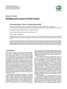
Fig. 1.Comparison between numerical approximation (solid line) withmanufacturer data (squares) of thepower curve.
(3)
with
A.
A., =l-c A.
(4)
9
The adopted equations (3) and (4) are extracted from [12-13] but the value of the constants Cl to C9 has been changed in order to get better correspondence with manufacturer data. To minimize the error' between the curves found in manufacturer 'documentation and the 'curve obtained using (3) and (4), a MATLAB routine is used to find the best values for the constants. Both the original constants values and the parameters used here are given in Table I. In Fig. 1, the power curve from the manufacturer documentation and from the numeric approximations of Table I are depicted. It can be seen in Fig. 1 that the two curves nearly coincide .for different wind speeds. The power coefficient, Cp, as a function ofthe tip-speed ratio, A, is plotted itt Fig. 2.
···i······..·(..··.. t ..·.. ·!.. ·······1··· ····i········t·········;······.. t·..······r······.. !···
0 1 .. .. .. . : .. .. ..
0.05 . • • •
e
5 np..potd ....
Fig. 2. Power coefficient vs, tip-speedratio. r--~--~--- ~ ----- --~
14.1 mI,
1800 1400
~ 1200
I
1000 800
1
TABLE I APPROXIMATION OFPOWER COEFFICIENT CURVE c, c. Cz Cl C6 Ct C9 I'
O.S
116
0 .4
S
21.0
0 .08
0 .03S
2'
0.44
12S
0
6.94
16.5
0
·0.002
600
300
400
500
Rolor epeed (rpm)
3'
1.06
112
0
1).2
16.5
0
·0.001
Fig.3. Mechanical power vs. rotorspeed fordifferent wind speeds.
1 ref. [13].2 • ref. [12],3 current work
- 163 -
71lE ELEVENTH INTERNATIONAL MIDDLE EAST POWER SYSTEMS CONFERENCE
(MEPCON'2oo6j
This mechanical torque of the wind turbine relates to the mechanical power as:
The angular generator speed CDr can be expressed In termsof the angular rotor mechanical speed : : ; .
:
:
:
~
:. _ .
.
•
:
•
•
:
"" ' . '
~ 1 0 1------.~·
_.
1_ _ -L . . . _ ! ._. .L_ .__ .L
o
02
04
0.6
0.8
1
1.2
_ . 1. . _ ' _. __. 1."_0-
1.4
1.6
1.8
6S.63V/krpm EOJ
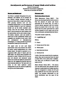
The switching frequency is 5kHz for both switches, which simplifies the implementation, The wind speed changes over a wide range as shown in Fig. 8. The PMSG speed to extract maximum power from the wind, the actual rotor speed, and the output voltage are shown in Fig. S. As it is clear, after the transient (starting) period, the rotor shaft speed follows the reference (optimal) speed for all wind speed values. The optimal PMSG speed is calculated from the wind speed, according to the manufacturer documentation, using a linear equation as: OJ,.! =36.52U.. + 3.5
(MEPCON'2oo6j
--, ~ ~-r--...,..--........,....--,----r-
; relspeed :
- 165-
:
:
:
0.8
1
1.2
1.4
;
;
l
1.6
1.8
2
.. --r -----,---...
!~ ttI , u, · · ,· ,j LI o
0.2
0.4
0.6
150 ~~-~r ; -'--T--;-'; --~ I 1201 _..~ · ti-;-,.;:~~-"" . -ojof'..".,....,.."'. -
···
(14)
where CDreI'is the reference speed (rpm). The output voltage is regulated at 125V at any wind speed. In this simulation, the capacitor Co represents the battery bank, and a resistive load of RL • .The output voltage is fixed after the starting period as shown in Fig. 5 by controlling the power switch Qz. It
;
2
~
.
60 ... .. ;.... :.. ... . ~ ... ..
U
M
. .. :. . .•.. l- . . . .
__
O~"""'.L --l.
o
..
M
~
.L-_.L..-I.
M 1 1.2 Time (sec)
U
U
.•. . '. . .. • •
.
. l -_
U
Fig.S. Wind.rotorand its reference speeds, andoutput voltage.
2
71lE ELEVENTH INTERNATIONAL MIDDLE EAST POWER SYSTEMS CONFERENCE
18001..----,--
.,-- - ..----,--
.,--
.
,
.
· .··
., , ..
4
.
i:
..----,--
-,--
the simulation results demonstrate the effectiveness of the proposed control.
..-- ,
1000 . ... • ~ .. . •. . :••. .• •; ... .• ~ ..•. .. ~ . " . ---.....,
.
:
E Dl . . ... ;:. . . . ...
•
•
.. .. .. .. . ., ... ..,_
•
4~
I
•
o
0.2
0.4
0,8
•
• •
• • • •
•
,
REFERENCES
• ••• •
•
"
O ==-_-'--' ~· --I
_L._-'--___I_
1.2
0.8
1.8
_L.____l
2
1.8
--,---r - ~ ~ I -...----,c---r-...--...,c--~ ~
0,4
:
;
·
..
"J
[
:
:
:
:
:
:
e ····· ~." " ,.:
.
.,
.
.
"'r'""1'" ···1····· :····· r·····:····· I
f
0...
0.8
0.8
.:
;.
1.2
:.. ..
I
I
I
1.4
1.8
1.8
.,
2
.
~: :: :1·::::::1: ::::1. ':.::1::.:::l:::::l:::::t:::::l::':: . . .,
-e
..
, ---,-_
0.2
. .
.,
·,
- , - _, - - , -_ - , - -L..
0.4
0.8
0.8
1
1.2
.
.
.
1.4
1.8
1.8
I
,
I
2
lime(sec) Fla. 6. Mect.UcaI power, power coefficient and tip-spced ratio. 3O r-~-~~. ~ ;- -~ . - ~' -~.-
···
l
~
.
.
...
20 . .... ~ . • . . • . : .. . ... : . •. . .. ~ . . .. . ;
10
.. .
.
...
+.·j·. ·-+.. ···~ . ··+·..·j·..·+.·.l. . ·j····· ::
0.2
0.4
:
0,11
.;
0.8
:
I
1.2
1.4
•
1.11
1.8
2
. . . . . .~ . . .
(1
(MEPCON'2oo6j
0.1 ..
O.M
··T··.. r-·..r ···"[···.. r ··r···-;- ..··-; ·..·T·..·
····1·· ···j······( ··-r--···i····.. j""····( ·..r---··("·· . . : . . : ~
0.2
0.4
0.11
0,8
1
1.2
1.4
1.11
1.8
2
TIme (Me)
FIg. 7. Mechanical driving torque and 'Its coefticlcnt
[IJ W. Fengxlang, H. Qingming, B. Jianlong..,d P. Jian, "Study on control $}Stem of lowspeedPM gencndor directdriven by wind turbine," In Proceedlnp of the 100' Electrical Mach/ne8 and Sy8terru(lCEMS200') Intemat/orral Co'lferenCe, vol.2, PlI. 1009-1012. [2] B. K. Kirke, "Evaluation of self·stlUtlng vertical axis wind turbines for stand alone applications," PhD the8/8. Griffith University,GoId Coast, Australie. Apr. 1998. [3J S. A. Papathanassious and M.P. Papadopoulus, "Dynamic behaviour of variable speed wind turbines under stochastic wind. "IEEE 7hvu. Energy CorrventOff, vol. 14, Dec. 1999, pp.1617·1623. [4J F. BllIlIbjerJ and Z. Chen, "Powerelectronics as.., enabling technology for renewable energy integration," J. Power Electron., vol.3, Apr.2003,pp. 81-89. [5] L.M. Popa, F. BleajerJ lIIId I. Boldea, "Wind turbine generator modelling and simulation where rotorspeed Is the controlled variable." IEEE 7ran.r. Inri. Appl., vol. 40, no. I, Jan.2004,pp. 3-10. [6J E. Muljadl, S. Droullhet and R. Holz,"Analysis ofpennanent magnet generator for windpower battery chafBIng," In Co'lference Proceed/np ofIEEE-lAS AnnualMeeting, vol. I, 1996,pp. 541-546. (7J A.M. De Broe, S. Drouilllet and V. Oevorglan, "A peak power tracker for small wind turbines In battery charging applications." IEEE Trtm.f. Energy Corrven/on, vol. 14, no. 4,Dec. 1999,pp. 1630-1635. [8J D.M. Whaley, W.L. Soong and N. Ertugrul, " Investigation of Switched-Mode Rectifier for Control of Small-Scale Wind Turbines," 'n Co'lference Proceed/nIP of IEEE-lAS Annual Meeting, vol.4, 2005,pp. 2849·2856. (9J T. Burton, D. Sharpe, N. Jenkins and E. Bossany~ WhJc/ energy handbook, JohnWiley&: Sons,Ltd, England: 2001,p. 6. [1OJ T. Ackennann, Windpower Inpower 8)'8terru, John Wiley &: Sons, Ltd, England: 200S,p. 33. [IIJ J.F. Manwell, J.G. McGowan, and A.L.Rogers, Windenergy expla/ned: theory, de8/gn and appllCQtltHI, John Wiley &: Sons, Ltd, Engllllld: 2002,p. 88. [12) J. G. SIootweg, H. Pollnder and W. L. Kling, ~Representing wind turbine electrical generating $}Stems In fundamental frequency simulations", IEEE Trans. Energy Conver8lon, vol. 18,no. 4, Dec. 2003, pp. 516·524. [13J S. Heier, "Grid integration of wind energy conversion systems", Cbicester, UK, Wiley, 1198. (14) A.G. Westlake, J.R. Bumbyand E. Spooner, "Damping the power-angle oscillations of a permanent magnet synchronous generator withparticular maence to windapplications, " lEE Proc. Ekct. PowerAppl.,vol.143,no. 3, May1996,pp.269280.
V. CONCLUSIONS A small wind power system using a vertical-axis wind turbine coupled with axial-flux pennanent magnet synchronous generator is completely modelled and simulated in transient conditions. The control algorithm is effective over a wide range of wind speed.The wind turbine is controlled to operate at optimal generator speed. Thus operating at maximum efficiency and extracting maximum power from the wind Into electricity. The output voltage of the buck-boost converter is controlled to be constant at any wind speed for battery charging purpose, and
-166-