2015 IEEE 4th International Conference on Cloud Networking (CloudNet)
Virtual Network Functions Placement and Routing Optimization Bernardetta Addis⇤ , Dallal Belabed† , Mathieu Bouet‡ , Stefano Secci†
†
⇤ LORIA,
France. Email:
[email protected]. Sorbonne Universit´es, UPMC Univ Paris 06, UMR 7606, LIP6. Email: {dallal.belabed, stefano.secci}@upmc.fr ‡ Thales Communications & Security. Email:
[email protected]
Abstract—Network Functions Virtualization (NFV) is incrementally deployed by Internet Service Providers (ISPs) in their carrier networks, by means of Virtual Network Function (VNF) chains, to address customers’ demands. The motivation is the increasing manageability, reliability and performance of NFV systems, the gains in energy and space granted by virtualization, at a cost that becomes competitive with respect to legacy physical network function nodes. From a network optimization perspective, the routing of VNF chains across a carrier network implies key novelties making the VNF chain routing problem unique with respect to the state of the art: the bitrate of each demand flow can change along a VNF chain, the VNF processing latency and computing load can be a function of the demands traffic, VNFs can be shared among demands, etc. In this paper, we provide an NFV network model suitable for ISP operations. We define the generic VNF chain routing optimization problem and devise a mixed integer linear programming formulation. By extensive simulation on realistic ISP topologies, we draw conclusions on the trade-offs achievable between legacy Traffic Engineering (TE) ISP goals and novel combined TE-NFV goals.
Fig. 1. VNF chaining with virtualized Customer Premises Equipment (vCPE).
A promising NFV use-case for carrier networks is the virtual Customer Premises Equipment (vCPE) that simplifies the CPE equipment by means of virtualized individual network functions placed at access and aggregation network locations, as depicted in Fig. 1. MANO operations must take into consideration the special nature of NFV architectures, such as the latency/traffic bounds at both the VNF node and the end-to-end levels, the fact that some VNFs can modify the incoming bitrate by compressing or decompressing it, etc. In this context, the paper contribution is as follows: • we define and formulate via mathematical programming the VNF Placement and Routing (VNF-PR) optimization problem, including compression/decompression constraints and two forwarding latency regimes (with and without fastpath), under both TE and NFV objectives. • we design a math-heuristic approach allowing us to run experiments also for large instances of the problem within an acceptable execution time. • we evaluate our solution on realistic settings. We draw considerations on NFV deployment strategies. The paper is organized as follows. Section II presents the state of the art on NFV orchestration. Section III describes the network model and the Mixed Integer Linear Programming (MILP) formulation. Analysis and discussion of optimization results are given in Section IV. Section V concludes the paper.
I. I NTRODUCTION With the emergence of Network Functions Virtualization (NFV) [1], [2] the attention of network virtualization research is now focusing on key aspects of NFV systems that were either not considered relevant or not conceived before industry effort at Standards Developing Organizations (SDOs). Key aspects that are worth being mentioned are the: • • • •
NFV service chaining provisioning; flow orchestration over VNF chains as a function of demand assignment to existing VNF chains or sub-chains; ingress/egress bit-rate variations at VNFs due to specific VNF operations (e.g., compression/decompression); VNF processing and forwarding latency as an orchestration parameter to take into account for emerging fastpath solutions such as [3].
ETSI is de-facto the reference SDO for the NFV highlevel functional architecture specification. ETSI specifies three layers for the NFV architecture: Virtual Network Functions (VNFs), the nodes; NFV Infrastructure (NFVI), including the elements needed to run VNFs such as the hypervisor node and the virtualization clusters; MANagement and Orchestration (MANO), handling the operations needed to run, migrate, optimize VNF nodes and chains, possibly in relationship with transport network orchestrators.
978-1-4673-9501-4/15/$31.00 ©2015 IEEE
1
2015 IEEE 4th International Conference on Cloud Networking (CloudNet)
II. BACKGROUND
nodes, A the set of arcs between nodes, Nv ✓ N the set of nodes disposing of NFVI server clusters. Given a set of edge demands D, each demand k 2 D being characterized by a source ok , a destination tk , a nominal bandwidth bk statistically representative for demand k, and a set of VNFs of different types to be traversed by edge flows, the VNF-PR optimization problem is to find: • the optimal placement of VNF nodes over NFVI clusters; • the optimal assignment of demands to VNF node chains. subject to: • NFVI cluster capacity constraints; • VNF flow compression/decompression constraints; • VNF forwarding latency constraints; • VNF node sharing constraints.
In the state of the art, preliminary works on NFV orchestration tend to map the problem into a Virtual Network Embedding (VNE) problem. This is for example the case of [4], where VNFs are treated as normal virtual machines (VMs) to be mapped on a network of VM containers interconnected via physical links that host logical links of virtual network demands. Similarly, authors in [5] propose a VNF chaining placement that combines location-routing and VNE problems, solving first the placement and then the chaining. In [6] the authors decouple the legacy VNE problem into two embedding problems: VNF chaining and VM embeddings, where a service chain is embedded on a VM, and each VM on physical servers. Each service chain has specific requirements as notably an end-to-end latency requirement. The placement and routing of VNF chains is a problem fundamentally different from the VNE problem. As in VNE, virtual network nodes need to be placed in an underlying physical infrastructure. However, differently from VNE, in VNF chaining: (i) the demand is not a multipoint-to-multipoint network connection request, but as a point-to-point sourcedestination flow routing demand and (ii) specific aspects of NFV such as forwarding latency behavior, ingress/egress bitrate changes, and chaining are not addressed in VNE, and their inclusion would further increase the time complexity. In this sense VNF chaining problem is closer to facility location problems, whereas VNE is a mapping problem. We believe the appropriate way to deal with NFV MANO decision problems is to define the VNF Placement and Routing (VNF-PR) problem directly tailored to the NFV environment, for the sake of time complexity, modeling precision and practical usability. This is also the approach adopted by a few papers in the literature [7], [8], [9]. In [7] the authors consider the online orchestration of VNFs, modeling it as a scheduling problem of VNFs and proposing heuristics to scale with the online nature of the framework. In [8] the authors consider a VNF-PR problem for data-center environments with both optical and electronic elements, formulating the problem as a binary integer programming problem, and propose a heuristic algorithm to solve it. In their work, VNF chains are set as an input to the problem. In [9] the specific Deep Packet Inspection (DPI) VNF node placement problem (with no chaining) is targeted, with a formal definition of the problem and a greedy heuristic algorithm to solve it. Our paper takes inspiration from these early works, yet goes beyond being more generic and integrating the specific features of NFV environments mentioned in the introduction.
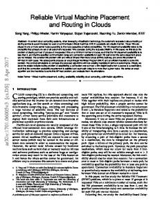
The optimization objective should contain both networklevel and NFVI-level performance metrics. In our network model, we propose as network-level metric a classical TE metric, i.e., the minimization of the maximum link utilization. As NFVI-level metric we propose the minimization of allocated computing resources. Furthermore, we assume that: • Multiple VNFs of the same type (i.e., same functionality) can be allocated on the same node, but each demand cannot split its flow on multiple VNF of the same type. • There are different VM templates for embedding a VNF, each with a different computing resource consumption and VNF forwarding latency performance. • The VNF computing resource consumption can be expressed in terms of live memory (e.g., RAM) and Computing Processing Units (CPUs), yet the model shall be versatile enough to integrate other computing resources. • Latency introduced by a VNF can follow one among the two following regimes (as represented in Fig. 2): – Standard: VNFs bufferize traffic at input and output virtual and physical interfaces such that the forwarding latency can be considered as a convex piece-wise linear function of the aggregate bit-rate at the VNF, due to increased buffer utilization and packet loss as the bitrate grows as shown in [3], [10]. This is the case of default VNFs functioning with standard kernel and hypervisor buffers and sockets. – Fastpath: VNFs use optimally dimensioned and relatively small buffers, and decrease the number of times packets are copied in memory, so that the forwarding latency is constant up to a maximum aggregate bit-rate after which packets are dropped; e.g., this happens for fastpath solutions such as [3]. Fig. 2 gives examples of forwarding latency profiles for the two cases (with two templates used for the tests). • For each demand and NFVI cluster, only one compression/decompression VNF can be installed. This allows us to keep the execution time at acceptable levels, without reducing excessively the VNF placement alternatives. • Each network node is interconnected with a NFVI cluster node (in the notations, to simplify, we use a single identifier for collocated network and NFVI nodes).
III. N ETWORK M ODEL We provide in the following a definition of the VNF Placement and Routing problem, and its formulation. A. Problem statement Definition Virtual Network Function Placement and Routing (VNF-PR) Problem Given a network graph G(N, A), where N is the set of
2
2015 IEEE 4th International Conference on Cloud Networking (CloudNet)
TABLE I M ATHEMATICAL N OTATIONS Na Na0 Nc Nv N A D R F Cf T
Fig. 2. Example of VNF forwarding latency profiles.
ok tk bk
B. Mathematical formulation
bmin k
sets access nodes duplication of access nodes, where demands are located aggregation/core nodes nodes where a VNF can be located, Nv = Na0 [ Nc set of all nodes, N = Na [ Nv set of all arcs, A ✓ N ⇥ N demands resource types (CPU, RAM, storage) VNF types set of possible copies of VNF of type f set of VM template configurations demand parameters origin of demand k 2 D destination of demand k 2 D nominal bandwidth of demand k 2 D minimal bandwidth of demand k 2 D maximal bandwidth of demand k 2 D 1 if demand k 2 D requests VNF l 2 F network parameters arc capacity link latency maximum traffic volume that can be switched capacity of node i 2 N in terms of resource of type r 2 R NFV parameters demand of resource r 2 R for a VM of type t compression/decompression factor for VNF f 2 F j-th latency function of f 2 F and aggregate bandwidth b if allocated on VM of type t, linear in requested bandwidth maximum allowed latency for a demand binary variables 1 if arc (i, j) is used by demand k 2 D 1 if demand k 2 D uses copy n-th of VNF of type f 2 F placed on node i 2 Nc on a VM of type t 1 if n-th copy of type of VM t is assigned to VNF of type f 2 F hosted by node i 2 Nc continuous non-negative variables flow for demand k 2 D on arc (i, j) flow for demand k 2 D entering in node i and using copy n of VNF of type f 2 F latency that demand k 2 D ‘suffers’ using VNF of type f 2 F hosted by node i 2 Nc order coefficient for node i in the path used by demand k
Table I reports the mathematical notations used in the bmax k mkl following Mixed Integer Linear Programming (MILP) formulation of the VNF-PR problem. We work on an extended graph ij (to distinguish between origin/destination nodes and NFVI ij Mi nodes), in which each access node i is duplicated in a node ir i0 . Arc (i, i0 ) will be added and all arcs (i, j) originating from 0 access node i will be transformed in arcs (i , j). rr rt µf We use three binary variables: xkij represents the pergft j (b) demand link utilization, hence the path used by the demand; n yif t represents the allocation of a copy of a VNF on a given L kn node; zif t represents the assignment of a given demand to xkij a certain copy of a VNF. To introduce the possibility of kn z if t compressing/decompressing flows for some VNFs, we need k to introduce the explicit flow variable ij and a compression n yif t kn parameter µf for each type of VNFs. Furthermore, if represents the flow of demand k entering node i and using k the copy n of the VNF of type f . ij kn if We now present the constraints. Single path flow balance: 8 k lif < 1 if i = ok X X 1 if i = tk 8k 2 D, 8i 2 N xkij xkji = cki : 0 otherwise j:(i,j)2A j:(j,i)2A (1) Flow and compression/decompression balance: VNF compression/decompression linearization constraints: X X X k k kn (1 µf ) if ij ji = X X f 2F,n2Cf j2N :(i,j)2A j2N :(j,i)2A kn k kn zif if ji + Mi (1 t) 8k 2 D, 8i 2 Nv (2) t2T j2N :(j,i)2A
Flow balance for access nodes: X X k ij
k ji
j2N :(i,j)2A
=
8 < :
=
j2N :(j,i)2A
j2N :(j,i)2A
k
b ·
Q
bk if i = ok f 2F :mkf =1 µf if i = tk 0 otherwise
8k 2 D, 8i 2 Na (3)
bmax xkij k bmin xkij k
8k 2 D, 8(i, j) 2 A
8k 2 D, 8(i, j) 2 A
kn if
(6)
t2T
8i 2 Nv , k 2 D, f 2 F, n 2 Cf (7) X kn Mi zif t 8i 2 Nv , 8k 2 D, 8f 2 F, n 2 Cf (8) t2T
One compression/decompression VNF per node and demand:
Coherence between path and flow variables: k ij k ij
8i 2 Nv , k 2 D, f 2 F, n 2 Cf X X k kn Mi (1 zif ji t)
kn if
X
(4) (5)
X
t2T f 2F,n2Cf :µf 6=1
3
kn zif t 1 8k 2 D, 8i 2 Nv
(9)
2015 IEEE 4th International Conference on Cloud Networking (CloudNet)
Utilization rate constraints: X k 8(i, j) 2 A ij U ij
kn The variable if represents the flow of demand k that enters node i and passes through the copy n of the VNF of type f (non-linear representation): X X X kn k k zif if = ( ji ) t
(10)
k2D
If there is no VNF, it cannot be used by any demand: kn n zif t yif t
8k 2 D, 8i 2 Nv , 8f 2 F, 8t 2 T, n 2 Cf
j2N :(j,i)2A
t2T n2Cf
The constraints can bePlinearized using (6)-(8), with the parameter Mi equal to (j,i)2A ji , which represents the If traffic does not pass by a VNF, it cannot use it: maximum quantity of flow entering node i. X kn zif xkji 8k 2 D, 8i 2 Nv , 8f 2 F, 8t 2 T |mkf = 1 Eq (4) and (5) allows to connect variables x and phi, in t j:(j,i)2A such a way that only and only if arc (i, j) is used by demand (12) k, that is xkij = 1, then variable phi can be different from zero. As the demand pass through VF that can compress or Each demand uses exactly one NFV of each type it asks for X X X decompress the flow, then we can determine kn Q upper and lower zif t = 1 8k 2 D, 8f 2 F : mkf = 1 (13) bound for the demand that are: bmax = bk f 2F :µf 1 µf and k Q i2Nc n2Cf t2T bmin = bk f 2F :µf 1 µf . k On each node at most a VM assigned for each VNF copy As mentioned before, we consider two objective functions: of a certain type: • TE goal: minimize the maximum network link utilization: X n yif 1 8f 2 F, 8i 2 N , 8n 2 C (14) c f t min U (20) (11)
t2T
Node resource capacity (VNF utilization): X X X n rr rt yif 8i 2 Nv , 8t 2 R t ir
•
(15)
f 2F n2Cf t2T
Preventing the formation of isolated cycles: ckj
cki + xkij
xkij )
|A|(1
Latency function linearization: X k dn lif gfj t ( Lmax (1 if ) d2D
8t 2 T, 8k 2 D, 8j 2 1..G
Maximum latency bound: X X X k xkij + lif L (i,j)2A
i2Nc f 2F
i2Nv f 2F t2T k2D r=‘CP U 0
The former objective allows taking into consideration the inherent fluctuations related to Internet traffic and therefore minimizing the risk of sudden bottleneck on network links. 8i 2 Nc , f 2 F, n 2 Cf The latter assumes the fact that today the first modular cost in virtualization servers, especially in terms of energy (17) consumption, is the CPU.
8k 2 D, 8(i, j) 2 A kn zif t)
(16)
C. Multi-objective math-heuristic resolution (18)
8k 2 D
We face a multi-objective problem: minimizing the maximal link utilization and minimizing the total virtualization cost at the NFVI layer. These two objectives are in competition; in fact, to obtain a low utilization, a large number of VNFs must be allocated. We decided to prioritize the objectives . We minimize first the maximal link utilization, and then the NFV cost, which reflects the ISP-oriented vision to improve the user quality of experience (strictly related to link congestion, especially for real-time services). In practice, in order to do our best to meet the second objective and allow the largest possible marginal gain, we perform a first optimization step to find the best solution accordingly to the first objective, and then, keeping the best value found in the first step as a parameter, we minimize the second objective. In fact, for a given optimal value of the first step, different possible configurations are available to the second step, and a large primary cost reduction can be achieved by this second step without losing with respect to the secondary objective. In order to reduce the computational time of the procedure, we performed an optimization procedure based on several steps. In the TE optimization, we subsequently optimize three models, starting from a simplified one, where no latency and compression/decompression features are present, to the
Eq. (3) represents the flow balance for the access nodes. At destination node the quantity of flows is set equal to the demand multiplied for all factors of compression of all the demanded VNFs. Eq. (2) represents the flow balance for a given node that has the possibility of hosting VNFs. We work under the assumption that given a node i, and a demand k, such demand uses at most a VNF f with a factor of compression/decompression µf 6= 1. If a demand passes through a VNF with a factor of decompression µf , then the out-flow of the node is proportional to the in-flow: X X k k ij = µf ji j2N :(i,j)2A
j2N :(j,i)2A
Using variable z that represents the assignment of demand to VNFs and subtracting the out-flow we get: X X k k ij ji = j2N :(i,j)2A
X
j2N :(j,i)2A
j2N :(j,i)2A
k ji
NFV goal: minimize number of cores (CPU) used by the instantiated VNFs: X XXX X n min rrrt yif (21) t
X X
(µf
kn 1)zif t
(19)
n2Cf t2T
4
2015 IEEE 4th International Conference on Cloud Networking (CloudNet)
complete model. The solution of each step is given to the next optimization phase. In the NFV goal optimization, a bisection procedure is used on the number of allocated VMs to guarantee solution optimality, even when in a single step the solver is not able to guarantee it. In order to allow a larger reduction of the total cost, at the price of a larger link utilization, an iterative approach can be used: increasing step by step the value of the first objective (TE) until the desired cost level of the second objective is found. Such an iterative procedure can have the advantage of providing to the second step of optimization a feasible solution (warm-start), which in many practical cases can reduce the computational time of the optimization.
capture the differences between the different cases, we limit to two VNF types per demand: a tunneling VNF (requiring decompression) and a firewall-like VNF. The NFVI layer is dimensioned so that there are enough computing resources to satisfy individually half of all the demands (i.e., excluding VNF sharing); NFVI access nodes are dimensioned so that they are composed of 5 CPUs, 80 GB RAM at each access node, twice and four times this quantity at aggregation and core nodes, respectively. Each case is emulated with 10 random demand matrices. For the standard case, we analyze in the following the results shown in Fig. 4 (NFV cost distribution), Fig. 5 (link utilization distribution), Fig. 6 (end-to-end and VNF forwarding latency distribution). We provide a detailed analysis in the following, with two points of views: what happens when we also consider the NFV cost in the objective function, and what happens when we make stronger the bound on the end-to-end latency. Then, we compare the standard case with the fastpath case.
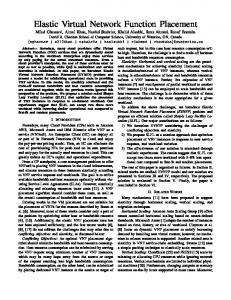
IV. R ESULTS We implemented our VNF-PR algorithm using CPLEX and AMPL scripting. We limited the execution time to 300s for each TE optimization phase and to 800s for each the NFV optimization phase. In almost all tests we reached the optimum for both objectives. The average time needed for the overall procedure is 15 min. with a worst-case optimality gap of 10%. We adopted the three-tier topology represented in Fig. 3 as a good reference for an Internet Service Provider network. Each access node is connected to two aggregation nodes, each aggregation node is connected to two core nodes, and core nodes are fully meshed. We consider all the nodes as NFVI nodes that can host VNFs. The demands are created uniformly in the interval [a, b] so that edge demands cannot create any bottleneck at the access links. The aggregation links are dimensioned so that there is a risk of link saturation (i.e., link utilization higher than 100%) if the traffic distribution is not optimized. The core links are such that there is a very low bottleneck risk. Link latencies are set as follows, to cope for the different geographical scopes: 1 ms for access links, 3 ms for aggregation links, and 5 ms for core links (so that routing through core links is facilitated). VNF processing latencies are set as in Fig. 2, for the fastpath and standard cases. We use two VM templates, one requiring 1 CPU and 16 GB of RAM, and one requiring 4 CPUs and 64 GB of RAM. We run tests setting for the end-to-end latency bound (L) with strict and loose values (15 and 20 ms, resp.). In order not to introduce unnecessary complexity to
A. TE vs. TE-NFV objectives sensibility We analyze the difference between the results with the TE objective and the results with the combined TE-NFV objective. • NFV cost (Fig. 4): the NFVI cost is significantly reduced with the TE-NFV objective, of roughly 70%. Indeed, a very high level of VNF sharing is enabled under the TENFV goal, for both latency bound situations. • Link utilization (Fig. 5): even if the median utilization slightly increases passing from the TE goal to the TENFV goal, in particular for aggregation links (roughly 5% more), the overall link utilization distribution is not significantly affected by adding the NFV cost minimization in the optimization goal. • Latency distribution (Fig. 6): the individual VNF processing latency contribution stays always below the ms, and a difference is barely visible using the TE-NFV approach. Thanks to the optimization, too high VNF sharing situations are avoided. This is a rather positive behavior considering that the Total latency (i.e., including propagation delays) is much higher, which could have hidden the importance of the VNF processing latency, which does not seem to be the case. B. Sensibility to the latency bound We analyze in the following the results highlighting the impact of the VNF chain latency bound L on the results. • NFV cost (Fig. 4): the global NFV cost remains almost constant passing from the weak to the strong latency bound. Under the TE-NFV goal, we cannot detect any relevant change of behavior. Instead, under the TE goal, an interesting behavior is that, making weaker the latency bound (L = 20ms), more tunnelling VNFs are installed at the aggregation layer (less in the access and core layers), while more firewall VNFs are installed in the access and core layers. This behavior suggests that better utilization of high-capacity links (aggregation-core and
Fig. 3. Adopted network topology and VNF-PR solution example.
5
2015 IEEE 4th International Conference on Cloud Networking (CloudNet)
(a) TE objective.
(b) TE-NFV cost objective.
Fig. 4. VNF node distribution across NFVI layers (standard case).
(a) L = 15ms (TE)
(b) L = 20ms (TE)
(a) L = 15ms (TE)
(b) L = 20ms (TE)
(c) L = 15ms (TE-NFV)
(d) L = 20ms (TE-NFV)
(c) L = 15ms (TE-NFV)
(d) L = 20ms (TE-NFV)
Fig. 5. Link utilization empirical CDFs (standard case).
Fig. 6. Empirical CDFs of latency components (standard case).
C. Standard vs. fastpath VNF switching
•
•
At last, we compare the standard case to the fastpath case. We consider only the weak latency bound (L = 20 ms) situation in order to better analyze the impact of the VNF forwarding mode (indeed, more stringent latency bounds have a relevant impact on the VNF chaining only). Fig. 7, Fig. 8 and Fig. 9 show respectively the NFV cost, link utilization, latency distributions, to be compared with the corresponding previous ones. We can observe that: • NFV cost (Fig. 7 vs. Fig. 4): fastpath VNF forwarding is more expensive in terms of NFV cost than the standard one, under both optimization goals. It is roughly 20% more expensive. This is a direct result of the maximum traffic bound that is set under the fastpath case and that is not set for the standard case. The value itself of the bound on the maximum traffic that can be forwarded is not that relevant (even if it can be easily tuned in practice),
core-core links) can be granted by relaxing a bit the latency bound because the tunnelling VNFs cause a bitrate increase, hence favoring the planning of firewall VNFs in access and core layers where more computing capacity is so made available. Link utilization (Fig. 5): in support of the abovementioned analysis, we can remark that under the weak latency bound, core links get more utilized (with a median utilization increase of roughly 20%) while access links get less utilized (at maximum) when the NFV cost is not added to the optimization goal. Latency distribution (Fig. 6): the end-to-end latency bound has a direct visible impact only on the total latency, which confirms the importance of the bound only for VNF chaining decisions rather than for VNF placement decisions.
6
2015 IEEE 4th International Conference on Cloud Networking (CloudNet)
(a) L = 20ms (TE) Fig. 7. VNF node distribution across NFVI layers (fastpath, L = 20ms).
• •
(b) L = 20ms (TE-NFV)
Fig. 8. Link utilization empirical CDFs (fastpath case).
rather its existence logically always makes fastpath more expensive than legacy standard NFV deployment with piece-wise forwarding latency behavior. This is the other side of the cost-performance trade-off, fastpath offering the better forwarding performance. On the other hand, the VNF node distribution shows that also with fastpath the core layer is much less used under the TE-NFV goal. Link utilization (Fig. 8 vs. Fig. 5): a similar behavior than the one detected for the standard case can be remarked. Latency distribution (Fig. 9 vs. Fig. 6): surprisingly, it appears that VNFs are better shared (higher VNF forwarding latency) under the fastpath forwarding mode, with a latency close to the maximum allowed by the second template. This is likely a side, yet desirable, effect of the already mentioned bound on the maximum traffic to be forwarded by the VNF, and it could be considered as a desirable NFVI network management property.
(a) L = 20ms (TE)
(b) L = 20ms (TE-NFV)
Fig. 9. Empirical CDFs of latency components (fastpath case).
a constant-latency forwarding time up to a maximum load) allows higher virtual network function resource sharing than using a standard forwarding mode (leading to a piece-wise forwarding latency behavior), with a 20% higher infrastructure cost.
V. C ONCLUSION
ACKNOWLEDGMENT This work was partially supported by the ANR Reflexion project (http://anr-reflexion.telecom-paristech.fr, contract nb: ANR-14-CE28-0019), and the European Institute of Technology (EIT) Digital Future Networking Service Action Line. We thank Nicolas Roubertier for helping with the simulations.
This paper proposes a VNF chaining and placement model, including an algorithm formulated as a mixed integer linear program, which goes beyond recent work at the state of the art. Our model takes into consideration specific NFV forwarding modes (standard and fastpath modes) as well as flow bitrate variations that make the allocation of edge demands over VNF chains unique yet complex. In order to master the time complexity while considering two different optimization goals – traffic engineering (TE) goal alone and TE goal combined with NFV infrastructure cost minimization goal (TE-NFV) – we adopt a math-heuristic resolution method. We run extensive tests to evaluate our algorithm on a threetier topology representing an ISP topology. The results show that the combined TE-NFV objective significantly reduces the number of VNFs in the network compared to the TE objective with almost no impact on the link utilization and on the latency. The bound on the end-to-end latency mainly affects the utilization of the links, core links being more utilized for weak bounds. The relaxation of this bound has another interesting effect for the TE objective: it pushes tunnelling VNFs, that increase the bitrate, at the aggregation level and firewall-like VNFs at the access and core levels. Another important insight of our analysis is that, using a fastpath forwarding mode (i.e., a VNF setting that allows
R EFERENCES [1] M. Chiosi and et al. Network functions virtualisation: An introduction, benefits, enablers, challenges and call for action. In SDN and OpenFlow World Congress, 2012. [2] ETSI. Network Functions Virtualization - Introductory White Paper. October 2012. [3] Intel. Impact of the Intel Data Plane Development Kit (Intel DPDK) on packet throughput in virtualized network elements. White Paper, 2009. [4] R. Guerzoni and et al. A novel approach to virtual networks embedding for SDN management and orchestration. In IEEE/IFIP NOMS 2014. [5] S. Mehraghdam, M. Keller, and K. Holger. Specifying and placing chains of virtual network functions. In IEEE CLOUDNET 2014. [6] H. Moens and F. de Turck. VNF-P: A model for efficient placement of virtualized network functions. In CNSM 2014. [7] R. Mijumbi and et al. Design and evaluation of algorithms for mapping and scheduling of virtual network functions. In IEEE NETSOFT 2015. [8] M Xia and et al. Network function placement for NFV chaining in packet/optical datacenters. In ECOC 2014. [9] M. Bouet, J. Leguay, and V. Conan. Cost-based placement of vDPI functions in NFV infrastructures. In IEEE NETSOFT 2015. [10] Intel. Network Function Virtualization Packet Processing Performance of Virtualized Platforms with Linux* and Intel Architecture. Technical Report, Oct. 2013.
7