The Dynamic Placement of Virtual Network Functions Stuart Clayman∗ , Elisa Maini† , Alex Galis∗ , Antonio Manzalini‡ and Nicola Mazzocca† ∗ Department
of Electronic and Electrical Engineering University College London, Torrington Place, London WC1E 7JE, UK Email: {s.clayman, a.galis}@ucl.ac.uk † Department of Electrical Engineering and Information Technology University of Naples Federico II, Via Claudio 21, 80125 Naples, Italy Email: {elisa.maini, nicola.mazzocca}@unina.it ‡ Telecom Italia Strategy - Future Centre Via Reiss Romoli 274, 10148 Turin, Italy Email:
[email protected] Abstract—This paper addresses the problem of managing highly dynamic network and service environments, where virtual nodes and virtual links are created and destroyed depending on traffic volumes, service requests, or high-level goals such as reduction in energy consumption. This problem will be one of the main technical challenges to be faced in the evolution towards Future Networks (FN). Emerging paradigms such as Software Defined Networks (SDN) and Network Function Virtualization (NfV) are concrete steps towards infrastructures where network functions and services will be executed as applications in ensembles of virtual machines (VMs) hosted in pervasive standard hardware resources located across a network. The paper argues that in order to manage these virtual infrastructures there is a need to introduce high-level systems orchestration. The paper describes an architecture based on an orchestrater that ensures the automatic placement of the virtual nodes and the allocation of network services on them, supported by a monitoring system that collects and reports on the behaviour of the resources. The orchestrater manages the creation and removal of the virtual nodes, as well as configuring, monitoring, running and stopping software on them. As a proof of these concepts, a distributed orchestrater prototype has been designed, implemented and tested with the results of different placement algorithms presented. Keywords—Placement, Orchestration, Management, Software Defined Network, Network Function Virtualization
I.
I NTRODUCTION
The progress of IT technology is impacting the evolution of both telecommunications networks and services infrastructures. Transport networks are going to become less and less hierarchical, with a limited number of simplified optical nodes, inter-connecting multiple local areas. In turn, these local areas, which are at the edge of current networks, are likely to become populated by small aggregations of nodes, (which include processing and storage capabilities), and also by a large number of mobile devices, smart objects, and connected things. In this evolution, software for management and orchestration will be the true challenge. Future Networks will rely more and more on such software, which will, in turn, accelerate the pace of innovation and will reduce costs (e.g., CAPEX and OPEX savings). It is argued that many of the FNs services c 978-1-4799-3360-0/14/$31.00 2014 IEEE
and functions will be virtualized and executed as applications in standard hardware nodes [1]. Emerging paradigms such as Software Defined Networks (SDN) and Network Function Virtualization (NfV) are going in this direction [2], by separating and abstracting network services and functions from the underlying resources. These paradigms largely exploit virtualization technologies for sharing and aggregation of resources, and for decoupling and isolating virtual network elements from the physical network. Moreover, the abstraction of virtualized network elements enables and simplifies the programmability of the network, increasing networking capabilities, allowing innovative service offerings, and providing higher cost efficiency [3]. The virtual resources include virtual machines (VMs) which execute either virtual routers or virtual service elements. These will be combined to create the virtual networks. They are aimed at better utilization of the underlying infrastructure in terms of (i) reusing a single physical or logical resource for multiple other network instances, and (ii) to aggregate multiples of these resources, in order to obtain more functionality, such as providing a pool of resources that can be utilized on demand and across multiple domains. These resources can be network components such as routers, switches, hosts, or VMs. As stated, these VMs can execute virtual routers or virtual service elements, but can also execute several network services. In virtual networks, a resource can be re-used for multiple networks or multiple resources can be aggregated for virtual resource. However, to manage these virtual resources effectively, there needs to be an effective orchestration and network management system [4]. For the above reasons, many challenges are related to the management and orchestration of virtual network resources. One of these challenges is the automated provisioning of networking and processing resources in the network according to the usage of the resources involved. One of these issues is to translate higher-level goals and policies resulting from resource allocation and optimization mechanisms into lowerlevel instructions and configurations. In order to manage these virtual resources, there needs to be an orchestrator that ensures the automatic placement and allocation of the virtual routers, supported by a monitoring system which can collect and report
on the behaviour of the resources. As an example, there may be a high-level goal which is “to reduce energy consumption”. To satisfy such a goal, the placement engine would need to have an algorithm which placed virtual routers ensuring that the least number of physical resources were used. Conversely, a goal such as “balance the load across all physical nodes” would need a different placement engine with a different algorithm. For fully effective operation, the placement engine should be swappable at run-time in order to make placements that match changing high-level goals and policies. The placement of virtual elements to physical resources is a complex issue given the highly dynamic nature of the resource usage and the start-up and lifetime of virtual elements. Previous work which addressed the placement of virtual machines in compute clouds includes [6] and [7]. The main aim of this paper is to describe an architecture based on an orchestrator which enables automated placement of virtual network and processing resources across the resources of the local areas. The orchestrator also manages the creation and removal of the virtual routers as well as configuring, monitoring, running and stopping applications in these virtual machines. Using an orchestrator, the utilization of infrastructure resources are monitored and the placement of the virtual routers is constantly updated to achieve optimal resource utilization according to goals policies set by the infrastructure provider. This paper is structured as follows: Section II outlines some use cases. Section III describes the proposed architecture. Section IV describes the testbed used for experiments, and Section V provides some results of the placement. Section VI presents some future work and finally, Section VII concludes the paper. II.
E VOLUTIONARY SCENARIO AND USE CASES
Some selected use cases show the key potential for using Software Defined Networks and Network Function Virtualisation to improve the quality of the applications for users, to increase business opportunities for both Service Providers and Telecommunication Service Providers, and also to enhance the market for value-added service providers. These trends will be coupled with the economic drive given by a myriad of new players entering the Telco/ICT markets. These factors are expected to impact the economic market in a way that will drive investment outside of the network infrastructure boundary and stimulate the advent of new communications paradigms [5]. The edges of the networks will be transformed into complex Micro Data Centers consisting of a number of diverse and autonomous, but inter-related nodes, devices, machines: this will create a “complexity” which has to be managed and controlled [8]. The network functions and services will be exposed, as opposed to being hidden as they are currently. They will be executed in VMs running mostly in these Micro Data Centers at the edge of the network, closer to the users and customers, and partly in VMs that are in mainstream Data Centers. The orchestration and management should be ensured by a system which knowing both infrastructure and network “states”, will be capable of optimizing configurations on the distributed nodes. Figure 1 presents an overview of a Future Network architecture that encapsulates these Micro Data Centers at the
edge of the network, connected by high throughput optical links and Core Routers to large Data Centers.
Data$Center
Dynamic(alloca+on( and(orchestra+on(of( network(func+ons
Data$Center Core Router
Core Router
Core Router
Core Router
Core(Network
Micro Data Center
Micro Data Center
Fixed(and(Radio( Access(Nodes
Micro Data Center
Micro Data Center Edge Networks
CPE
Figure 1: Evolutionary network scenario: edge networks This Future Network architecture is being planned for the following 3 telco use-case examples. 1) Provisioning end-to-end services across different Edge Networks: A service provider may want to provide end-toend ICT services to users who are attached to edge networks even if belonging to different network providers. This could be achieved by operating an overlay platform capable of hooking, managing and orchestrating all the virtualized resources and functions made available by the different network providers. 2) Harnessing storage and computing idle resources at the edge: Daily there are plenty of idle or less utilized resources in networks and services platforms. Harnessing these idle resources could allow optimizing CAPEX, whilst adopting new business models. Obviously not all services could be provided by using idle resources: examples of provisioned services will be CDN-like services, content sharing, data collections, aggregation, transformation, optimal re-distribution of VMs across the set of networks and servers and providing stabilization of the local networks following electricity demand-response loops, etc. Also in this use-case a platform is necessary for virtual resources and functions monitoring, allocation and move. 3) Follow-me personal data and services: Data and ICT services (seen as apps executed as sets of VMs) will follow the users when they are moving from one network attachment point to another one, even across different edge networks. Management and orchestration capabilities should allow this “follow-me” service whereby these VMs will be moved seamlessly. Moreover, data and services associated to users can be even federated to build distributed virtual data centers at the edge at costs which are a small and a fraction of traditional clouds. All of the above use-cases have as a foundation the Future Network with Micro Data Centers at the edges of the network and Data Centers in the network, combined with virtualised Software Defined Networks. For these usecases to be deployed it is necessary that the execution of the network functions and service elements are dynamically
The driving forces for both Software Defined Networks and Network Function Virtualisation have been presented together with the evolutionary scenario and use cases which would utilize SDN and NfV within a Future Network system. In this section we present an overview of the Management and Orchestration Architecture which is needed in order for such networks to operate.
…
Management Applica)on
Applica)on Layer
In general, from an architectural viewpoint, network functions and services can be defined as a number of software components with their accompanying context together with configuration parameters. The provisioning of a service involves the creation of a IT infrastructure, followed by the installation of all necessary software components into the infrastructure, and finally to configure and start those components. With SDN and NfV these processes can be simplified as the infrastructure provides a platform from which virtual machines can be run. SDNs can be directly manifested as virtual network topologies which need to be setup, have a managed lifecycle, and need to be shutdown - all under software control.
Management Applica)on
Management Applica)on
Monitoring8 Manager
Placement Engine
Orchestra)on Layer
a) separation – the service network and the infrastructure network are kept separate. The FN will reduce mutual dependency between the infrastructure and the services. A VN of a service needs to be separated from the infrastructure used by an infrastructure provider, similarly to the manner in which a virtual compute environment is separated from the physical host. b) isolation – a VN of one service is isolated from all other VNs services. The FN will isolate services, such that possibly competing virtual elements may securely and reliably share the infrastructure provider resources whilst being unaware of the other services.. Isolated VN services need to be offered side by side while sharing network resources of the infrastructure provider. c) elasticity – a VN can grow or shrink as necessary. The FN will offer an elastic and extendable environment so that network service customers will be able to adjust the size of their network on demand. A VN service needs to enable network elasticity. d) federation – a VN can span over more than one domain. the FN will form a federation of local areas so that each area offers an inter-changeable pool of resources allowing service and resource migration without barriers. An interchangeable VN service needs to be offered across local areas such that network service consumers would not be concerned by the area of the infrastructure location, the physical network used, or its configuration.
M ANAGEMENT AND O RCHESTRATION A RCHITECTURE
Virtual Router
Global8Controller Service8 Orchestrator Monitoring Data
Abstrac)on Layer
As stated, the focus of this paper is the dynamic management and orchestration of virtual networks (VNs), with particular attention paid to placement of these virtual resources. The physical resources will be shared by multiple virtual networks which are independent of each other and are allocated to different customers of the network. Each virtual network (VN) is viewed as a managed network service by the management software. All managed network services are mapped to the available resources which allows users of the network service to access it, just like they would access a physical network service. For full operation of the managed network services, the management and orchestration needs to ensure that each virtual network (VN) has separation, isolation, elasticity, and federation. The advantages of these attributes for the virtual networks are explained further:
III.
Infrastructure Layer
allocated somewhere in the physical network and executed by virtual resources.
Local8Controller8/8Network8Hypervisor Monitoring Data
Virtual Router Virtual8Infrastructure
Host
Host
…
Virtual Router
…
Host
Host
Data8Center8and8Network8Infrastructure
Figure 2: Overall system architecture and components
The Future Network implementation will provide the required virtual overlay for each service, as well as the dynamic and optimal allocation of VN to physical resources. As a consequence of network service elasticity and local area site management policies, virtual resources belonging to a same network service may be placed across different sites.
The architecture for the Management and Orchestration has 4 main layers. Figure 2 depicts an overview of the architecture. The layers are:
Such management and orchestration are required for the above use-cases to be deployed as it will allow fully software defined and controllable networks. These soft VNs need to setup, have a managed lifecycle, and need the topologies to be shutdown - all under software control. Furthermore, it is necessary that the VN elements are dynamically allocated somewhere in the physical network using a placement algorithm.
1) the Application Layer which executes Management Applications that define the software components and network functions of a network service together with their configuration parameters. 2) the Orchestration Layer is a software element which does most of the management and orchestration and is in charge of managing the full lifecycle of the virtual routers in the network and the allocation of the applications running
on the virtual nodes. It provides a Global Controller which contains a Service Orchestrator which does the orchestration of the all elements of a service, a Monitoring Manager which collects and managed all of the monitoring data received from the Infrastructure Layer, including virtual and physical resources, a Placement Engine which is involved in the placement of the virtual routers. The Global Controller is also responsible for the allocation of their applications. 3) the Abstraction Layer contains a software element which presents an abstraction for starting, stopping, and configurating virtual elements. It provides a Local Controller that acts as a Network Hypervisor, and works in a similar way to a host level Hypervisor managing virtual machines. 4) the Infrastructure Layer contains both the Virtual Infrastructure which represents the virtual resources (i.e. the virtual routers) that make up the virtual networks, and the Data Center Infrastructure which are the physical resources that are the hosts running the VMs. In general, the Global Controller is a distributed management infrastructure that has centralized functionality and it is responsible for the setup, configuration, optimization, and shutdown of the network entities. As depicted in Figure 2, it takes input from various Management Applications regarding various requirements (e.g. network resources or response time) and then configures the network nodes through a set of Local Controllers. In order to manage the challenging and dynamic infrastructures of virtual networks there needs to be a monitoring system which can collect and report on the behavior of both the physical resources (e.g. cpu usage, memory usage) and the virtual resources (e.g. utilization level of the virtual links). These monitoring data items are sent to the Global Controller so that it can use the monitoring information in order to make decisions regarding network strategies. In particular, it may decide to add new nodes in order to fulfil the high-level policies and goals which are network operator requirements. In this way, the virtual network topology changes dynamically according to the network virtual resources usage. The following subsections describe in more detail each of the layers. A. Application Layer As stated this layer executes Management Applications that define the software components and network functions of a network service together with their configuration parameters. There maybe many Management Applications which can interact with the Orchestration Layer. It is expected that some of the Management Applications will be simple, whilst others will be more complex. All of them will interact with the Orchestration Layer via a well-defined API. B. Orchestration Layer The Orchestration Layer is responsible for the placement of the virtual routers, the allocation of service components and functions running on the routers as applications. In particular, it is responsible for instantiating the virtual routers as it is the software element which does most of the management and orchestration and is in charge of managing the full lifecycle
of the virtual routers. Mainly, the Orchestration Layer has the following functions: i) it starts and stops the Local Controllers on each physical machine; ii) it acts as a control point for the platform by sending out the command and, iii) it acts as a management elements for the platform by collecting monitoring data and enabling reactive behaviour. This layer is composed of different components: namely the Service Orchestrator, the Monitoring Manager and the Placement Engine. The Service Orchestrator is the component in charge of performing the automatic deployment of the function/service as application running on the virtual routers. The Placement Engine is the component in charge of performing the actual placement of the virtual routers according to the initial topology and the usage of the virtual network elements. This is an important feature because, when we configure a network, considering some initial information, some of these parameters may change during the course of the system’s operation and a reconfiguration may be required to maintain optimized collection of information. For this reason, our approach considers a mechanism to achieve adaptation in a flexible manner. The decision on the Placement Engine is encoded in an algorithm which can be rather simple, such as counting the number of virtual routers on a host, or it can be based on a set of constraints and policies that represent the network properties. In this work we have considered i) infrastructure based measures for the placement of the virtual nodes and ii) as constraints, the usage of the virtual network entities (in this case, the usage of the virtual links) for placement. The results of using different Placement Engines will be highlighted later in this paper. The Monitoring Manager is an important component of the architecture and its monitoring function is a vital part of a full control loop that goes from the Global Controller, through a control path, to monitoring probes which collect and send data, back to the Global Controller which makes decisions based on the data. By using various probes in many parts of the whole system, much monitoring data is sent to the Global Controller, which processes the data and can adapt the network to observed changes. Each virtual router has a probe to monitor the usage of the network resources (e.g. the state congestion of the links). The data provided by the probes is collected by the Monitoring Manager and used by the Global Controller to create or remove the virtual routers according to the current state of the network. The monitoring software used in this paper is called Lattice and was developed within the RESERVOIR project and has been used for monitoring virtualised services in federated cloud environments [9], for monitoring virtual networks [10], and as the monitoring system for an Information Management uses Information Aggregation Points and Information Collection Points to aggregate, filter, and collect data in scalable manner within virtual networks [11]. Lattice [12] has been proven as ideal for the task of collecting monitoring data in this type of dynamic network environment.
Host
C. Abstraction Layer
Host Local Controller
This layer offers the capabilities for interacting between the Orchestrator and the Infrastructure Layers providing an abstraction. It contains the Local Controller software element which presents a common abstraction for starting, stopping, and configurating virtual elements.
Router
Router
Router Router
Router
Global Controller
Service Orchestrator
Placement Engine
Router
Router
Monitoring Manager
Router Local Controller
Host
Host
At the bottom, the Infrastructure Layer consists of a number of virtual routers, which is the Virtual Infrastructure, instantiated in a number of physical machines (or hosts), which is the Data Center Infrastructure. The virtual routers are logically independent software entities which, as a real routers, communicate with each other via network interfaces. The network traffic is made up of datagrams, which are sent to and from each router. Each virtual router can be dynamically created, dynamically destroyed in the virtual network. In fact, each router is connected to a Local Controller which sends the instructions to start up or shutdown routers on the local machine and for routers to setup ot tear-down connections with other virtual routers. IV.
Router
Router
A single Local Controller is started on each physical host that needs to execute virtual routers, and works in a similar way to a host level Hypervisor managing virtual machines. It is a Network Hypervisor which has the following functions: i) it starts and stops virtual routers; ii) it tells routers to create and remove virtual network connections, and iii) to get or set attributes on routers or links. D. Infrastructure Layer
Local Controller
T ESTBED
This section describes the testbed and methods used to test the Management and Orchestration Architecture. For the purpose of this paper we will will only look at collecting experimental data for various Placement Engines. To validate our design and architectural work, a working implementation of the architecture explained in the section III has been created. The experiments used the Very Lightweight Service Platform (VLSP) [14] which has been implemented by University College London for the purpose of testing and evaluating various aspects of Software Defined Networks and highly dynamic virtual environments. The VLSP testbed consists of a large number of software routers, each running inside Java Virtual Machines (JVMs). These virtual routers execute on a smaller number of physical machines. The virtual routers are logically independent software entities which cannot communicate with each other except via network interfaces. The testbed has been validated in previous work we have undertaken on virtual networks and highly dynamic networks [11] [13]. The testbed set up has three components: (i) the main component is the Router itself, which runs inside a JVM; (ii) a per-host controller, and (iii) a supervisor and experimental controller. The routers are complemented by a lightweight perhost controller called the Local Controller which has the role of sending instructions to start up or shut down routers on the local machine and to inform routers to initiate or tear down connections with other routers; and the whole testbed and experiment is supervised by a Global Controller.
Figure 3: Mapping and allocation of elements to hosts
The testbed is configured with the Global Controller on one host, and the Local Controllers running on any host that is to execute virtual routers. Under control from the Global Controller, individual Local Controllers are requested to start up a new virtual router when these new routers are needed. The choice of Local Controller is decided by the Placement Engine. As described earlier, the Placement Engine uses an algorithm to determine which is the best host to put a router onto. The Global Controller also sends requests, via a Local Controller, to connect virtual routers together via virtual network links. To highlight how these components are distributed across the physical resources, consider a micro data center with 4 hosts. We see depicted in Figure 3, how these components are placed and how they interact. In the bottom left host the Global Controller is executing. It has the Service Orchestrator, the Monitoring Manager, and the Placement Engine as subcomponents. The other 3 hosts each have a Local Controller. The dashed line shows the control path from the Global Controller to all of the Local Controllers. After requests have been sent Global Controller
Local Controllers
Router
Routers
Router Router
Router
Router
Router
Router
Router Router
Router
Figure 4: Control path to virtual routers and virtual links
to create virtual routers and virtual links, we observe a virtual topology that spans across these 3 hosts. The solid black line represents the virtual links. An alternate view of these components, showing a layered view, separates the control path from the virtual network. In the VLSP testbed, the virtual routers are autonomous entities and therefore the virtual network executes independently from the control elements. The control layers interact with the virtual layer. We see this view depicted in Figure 4 A. Router Networking The virtual router is implemented in Java and is a relatively complex software entity. The routers have virtual network connection to the other virtual routers they are connected to, and exchange routing tables to determine the short path to all other routers. Data packets are sent between routers and queued at input and output. A system of ports (like the current transport layer ports) is exposed with a DatagramSocket interface very similar to standard “sockets”. Virtual applications can be run on the virtual routers and can listen to and send data on their associated virtual sockets. Datagrams have headers with a source address, destination address, protocol, source port, destination port, length, checksum and TTL. Many of the features of real IP packets are replicated in the virtual domain. As such, we can take Java software that runs on real hosts, and run it on the virtual routers, with a small effort required to make the Socket code conform the virtual DatagramSocket interface. B. Routing and packet transmission Routing in these virtual routers is based on distance-vector routing. We have incorporated the split horizon hack and poison reverse. To prevent routing storms, minimum times between table transmissions are set. In addition, because the experiment here demands a certain “churn” of virtual routers, addresses which disappear permanently must be dealt with. In distance vector routing it is well-known that dead addresses can leave routing loops. This is dealt with in the current system by implementing time to live (TTL) in packets (so that packets in a routing loop expire rather than fill the network) and also implementing a maximum routing distance beyond which a router is assumed unreachable and removed from routing tables (so that the routing loops do not persist forever). The virtual applications can listen on virtual ports and send datagrams to any virtual address and port. Packets are queued both inbound and outbound. The outbound queue is blocking in order that transmitting applications can slow their sending rate. The inbound queue is tail-drop so that when too much traffic is sent drops will occur somewhere. TTL is decreased at each hop and, on expiry, a “TTL expired” packet is returned - this allows the virtual router system to implement traceroute as a virtual application. Virtual routers in the system send all traffic, including routing tables and other control messages, via the virtual network sockets. UDP-like, that is, delivery is not guaranteed and a failure to deliver will not be reported to the application (although if the router on which a virtual application runs has no route to the host this can be reported to the application).
C. Start up and shutdown The start up and shutdown of virtual routers is managed by the Global Controller and is performed by the Local Controller which resides on each host. A virtual router will be started on the same physical machine as the Local Controller. The Local Controller is also used to shutdown a virtual router or to control the connection of virtual routers with virtual links. The Local Controller behaves in the same way a hypervisor does in other virtualised environments and can also pass on Global Controller commands to Routers. The start up and shutdown of virtual routers can be managed by the Global Controller. It is configured to create different probability distributions for router creation, router lifetimes and for new virtual link inter-arrival times. D. Monitoring The underlying monitoring framework used by the testbed on the routers, is known as Lattice, is described in [9] and [10]. The Lattice monitoring system has been used successfully to provide data on all of the virtual elements and the running services of a cloud computing service environment [9] as well as for virtual networks [10]. The measurements supplied have been used for service and network management. In many systems, probes are used to collect data for system management. In this regard, Lattice also relies on probes. However, to increase the power and flexibility of the monitoring we introduce the concept of a data source. A data source represents an interaction and control point within the system that encapsulates one or more probes. A probe sends a well defined set of attributes and values to a data consumer at a predefined interval. In Lattice we have fully dynamic data sources, in which each one can have multiple probes, with each probe returning its own data. The data sources are able to turn on and turn off probes, or change their sending rate dynamically at run time. Furthermore, data sources can add new probes to a data source at run-time. By using this approach we are able to instrument virtual routers on-the-fly system without having to restart them in order to get new information. Each virtual router has at least one probe which can generate data. Monitoring data is also collected from each Local Controller. This data is send to the Monitoring Manager of the Global Controller which processes it. This is the data that is used by the Placement Engine for determining where a new virtual router is placed. Now the testbed has been described, the experimental results derived from test runs undertaken on the testbed will be presented. V.
E XPERIMENTAL R ESULTS
This section describes work performed and presents some experimental results using the VLSP testbed. For the purpose of this paper we will will only look at collected experimental data for various Placement Engines. The evaluation of other Orchestration elements, such as the Service Orchestrator, are to be covered in other papers. We show how the Placement Engine can make a decision which will enable the starting of
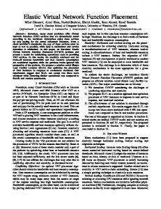
different virtual routers on different physical hosts depending on a set of factors. A Placement Engine is a software component that encapsulates an algorithm for choosing the “best” destination to place a new virtual router. Placement Engine algorithms can be based on infrastructure metrics or on virtual network metrics. It is possible to write many different Placement Engines which rely on different metrics and algorithms. The Placement Engine is a configurable module that can be changed as needed according to different placement strategies. From the previous descriptions of the Architecture and the Testbed, the Placement Engine is a component of the Global Controller. The choice as to which Placement Engine to run is dependent on the high-level goals and policies that are set for the whole of the networked system. As an example, there may be a high-level goal which is “to reduce energy consumption”. To satisfy such a goal, the placement engine would need to have an algorithm which placed virtual routers ensuring that the least number of physical resources were used. Conversely, a goal such as “balance the load across all physical nodes” would need a different placement engine with a different algorithm. To highlight how these placement algorithms perform we have devised an experiment whereby new routers and new links are created using a probability distribution. The virtual routers are created using a Poisson process (with exponential distribution of inter-arrival times) as this has been shown to be a realistic distribution for a number of real traffic arrival processes on the current Internet [15, table 3]. Also, each new virtual router has a randomized “lifetime”, so a virtual router can shutdown at run-time. Links are added between nodes as a random process, with every virtual router having one link plus a number of extra links, with a Poisson distribution. The routers are linked at random, so we observe that older routers tend to acquire more links. This experimental setup provides a highly dynamic and adapting network scenario with which to test the Placement Engines. For the tests we created a testbed scenario that utilizes 4 hosts in a configuration presented in Figure 3 and Figure 4. This will give us placement data for 3 hosts. Although the number of hosts used for real virtual networks is likely to be considerably higher than 4, having 3 allows us to present our results more clearly. We have considered three different Placement Engines for the same experimental setup, using the randomly generated virtual topology. The algorithms embedded in each of the Placement Engines are based on monitoring data from the infrastructure or monitoring data from the virtual network. Both Least Used (Figure 5) and N at a time (Figure 6) are based on infrastructure data, and Least Busy (Figure 7) relies on virtual network monitoring data. Figure 5, Figure 6 and Figure 7 show the number of virtual routers allocated on each host (shown on the y-axis) versus the time of the experimental run (shown on the x-axis). The hosts: host 1, host 2 and host 3 represented by blue, green and yellow lines respectively. Due to the random creation of virtual routers, combined with a randomized router lifetime, we see that the number of routers allocated to a host can do down as well as going up.
20
15
10
5
0 00:00:00
01:40:22
03:06:34
04:43:21
06:23:03
07:55:24
09:32:34
Figure 5: Placement Engine: Least Used
20
15
10
5
0 00:00:00
01:35:26
03:10:21
04:45:45
06:24:24
07:53:57
09:23:49
Figure 6: Placement Engine: N at a time: N = 5
20
15
10
5
0 00:00:00
01:33:25
02:59:18
04:33:14
06:09:27
07:36:37
09:11:00
Figure 7: Placement Engine: Least Busy
A. Least Used Host Here we present the Least Used placement algorithm. This collects the number of virtual routers allocated to each physical host and chooses the host that has the least number of virtual routers. If more than one host is at the minimum level, then a random host is chosen. This algorithm is a kind of load balancing algorithm as it tries to get a similar number of routers on each host. Observation of Figure 5 shows that the allocations are very similar for each host.
B. N at a time in a Host Here we present the N at a time placement algorithm. It tries to allocate N routers at a time into a single host. In this run, N = 5. If the number of routers is a factor of N, then the algorithm chooses are different host. When all the hosts are packed with a factor of N, then a random host is chosen. It too collects the number of virtual routers allocated to each physical host in order to make a decision. This algorithm is amenable for energy saving, as hosts that are not being used can be placed into a “power saving” state. Observations of Figure 6 show that allocation pattern is very different from the Least Used algorithm. Furthermore, as routers reach the end of their lifetime we see them disappearing from the allocation count, but the algorithm still tries to pack in N routers to a host. C. Least Busy Host Here we present the Least Busy placement algorithm. It tries to determine the host that is least busy in terms of virtual network traffic. It collects monitoring data from all the the virtual routers in the virtual network and calculates how much virtual traffic has been sent on each of the hosts. The host that has the lowest amount of traffic since the last placement decision is chosen as the host for the current placement. This algorithm is useful in contexts where the QoS of the virtual network is important as it places virtual routers close to other virtual routers that are not sending much traffic. Observations of Figure 7 show that the allocation pattern is again different from the previous two placement algorithms. This placement is not impacted by any infrastructure monitoring data, only virtual network traffic. As the traffic decreases on a host then the number of routers allocated to that host increases. These fluctuations, combined with router death, show a marked variation from Least Used and N at a time. The results presented here demonstrate that the different embedded algorithms in each of the Placement Engines give very different placement strategies for the virtual routers. It is expected that over time the placement algorithms for virtual routers will become more complex and factor-in metrics from both infrastructure and virtual resources. These placement engines may be able to utilize or share some algorithmic elements from compute cloud placement algorithms such as [6] and [7]. By having a detailed understanding of the behaviour of these different placement algorithms, it will be possible to choose the best Placement Engine to achieve fully effective operation. The placement engine should be swappable at runtime in order to make placements that match changing highlevel goals and policies. Such flexibility is a key aspect of a management and orchestration system. VI.
F UTURE WORK
As we have seen, the different embedded algorithms in each of the Placement Engines give very different placement strategies for the virtual routers. Future work will be consider other placement algorithms, which we expect to get more complex and to encapsulate multiple metrics. Futhermore, we wil investigate how placement strategies across multiple data
centers can be used, by considering existing cloud computing strategies or by defining strategies that are specialized for virtual networks. It is also planned to investigate the definition of utility functions whose minimization/maximization characteristics could provide the criteria for the dynamic placement of virtual nodes and the traffic engineering. Two main reasons are motivating the use of utility functions: (i) is that they allow for a separation of concerns between the analysis of the data and the planning and execution mechanisms (by an appropriate optimization algorithm); and (ii) is that they serve as a very high-level specification of the behavior of a network and service infrastructure. This allows business objectives to be directly translated into service level objectives when used with an appropriate optimization and modelling algorithm. Examples of metrics for utility functions includes QoS/QoE parameters, such as response time for processing capabilities, throughput for networking, etc. On the other hand, it should be noted that designing utility functions might be quite complicated and there might be scalability issues to be investigated. Another alternative could be formulating the criteria in terms of simple linear integer programming problems and then solving them with proper algorithms and/or heuristics [16]. As the placement of a virtual router has a direct impact on the behaviour of the whole networked system, we also plan to work on run-time migrating placement strategies. In particular, we will investigate the possibility of moving virtual routers in different locations in the network in order to optimize and factor-in the usage of physical resources and link level usage. VII.
C ONCLUSION
In this paper we have described a multi layer architecture for supporting SDN and NfV. The main Management and Orchestration layer defines a Service Orchestrator, a Monitoring Manager, and a Placement Engine. The latter, in particular, enables automated placement of virtual network and processing resources across the physical resources of the network. The experimental work presented highlights how the placement of the virtual routers is constantly updated to achieve adaptive resource utilization. As a proof of this concept, the architectural elements have been designed and implemented and some experimental results using the VLSP testbed presented. In particular, we have shown how Placement Engines can start different virtual routers on different physical hosts depending on different factors, such as infrastructure metrics or virtual network metrics. These results have been performed on a testbed of just 4 hosts. However, the VLSP testbed is a fully distributed implementation designed and built for the purpose of testing and evaluating various aspects of Software Defined Networks and highly dynamic virtual environments. It is highly scalable, and has been run with experimental virtual networks with over 700 virtual routers. The results presented here demonstrate that the different embedded algorithms in each of the Placement Engines have different behaviours and give very different placement strategies for the virtual routers. It is expected that over time the placement algorithms for virtual routers will become
more complex and factor-in metrics from both infrastructure and virtual resources, and also to consider placement across multiple data centers. ACKNOWLEDGEMENT This work is partially supported by the European Union DOLFIN project no. 609140 of the 7th Framework Program. R EFERENCES [1]
[2] [3]
[4]
[5]
[6]
[7]
[8]
[9]
[10] [11]
[12] [13]
[14] [15]
[16] [17]
ETSI, Network Functions Virtualisation (NFV) ETSI Industry Group, started in Jan 2013 http://portal.etsi.org/portal/server.pt/community/NFV/367 ETSI, Software-aware and Management-aware SDN, Initiative presented at 3rd ETSI Future Networks Workshop 9-11 April 2013 A. Galis, S. Clayman, L. Mamatas, J. Rubio-Loyola, A. Manzalini, S. Kuklinski, J. Serrat, T. Zahariadis, Softwarization of Future Networks and Services - Programmable Enabled Networks as Next Generation Software Defined Networks, IEEE Software Defined Networks for Future Networks and Services (SDN4FNS) 11-13 Nov 2013, Trento Italy A. Galis, J. Rubio-Loyola, S. Clayman, L. Mamatas, S. Kuklinski, J. Serrat, T. Zahariadis, Software Enabled Future Internet - Challenges in Orchestrating the Future Internet, 5th International Conference on Mobile Networks and Management (MONAMI 2013), 23-25 Sept 2013, Cork, Republic of Ireland, Matsubara, D., Egawa, T., Nishinaga, N., Kafle, V. P., Shin, M. K., Galis, Toward Future Networks: A Viewpoint from ITU-T, IEEE Communications Magazine, March 2013, Vol. 51, No. 3, pp: 112-118 D. Breitgand, A. Epstein, SLA-aware Placement of Multi-Virtual Machine Elastic Services in Compute Clouds, IFIP/IEEE International Symposium on Integrated Network Management (IM’11), May 23-27, Dublin, Ireland, 2011 D. Breitgand, A. Epstein, Improving Consolidation of Virtual Machines with Risk-aware Bandwidth Oversubscription in Compute Clouds, ACM/IEEE INFOCOM’12, Track II, 2012 A. Manzalini, R. Minerva, E. Dekel, Y. Tock, E. Kaemfer, W. Tavernier, K. Casier, S. Verbrugge, D. Colle, F.. Collegati, A. Campi, W. Cerroni, R. Vilalta, R. Munoz, R. Casellas, R. Martinez, N. Mazzocca, E. Maini Manifesto of Edge ICT Fabric, Proceedings of 17th International Conference on Intelligence in Next Generation Networks, 15-16 October 2013, Venice, Italy. , October 2013 S. Clayman, A. Galis, C. Chapman, G. Toffetti, L. Rodero-Merino, L.M. Vaquero, B. Rochwerger, Monitoring Service Clouds in the Future Internet, in Future Internet Assembly, pp. 115-126, April 2010. S. Clayman, A. Galis and L. Mamatas, Monitoring Virtual Networks With Lattice, ManFI 2010, IEEE/IFIP, Osaka, Japan, 19-23 April 2010 S. Clayman, R. Clegg, L. Mamatas, G. Pavlou and A. Galis, Monitoring, Aggregation and Filtering for Efficient Management of Virtual Networks, 7th International Conference on Network and Service Management (CNSM), 2011, Paris, Oct 2011 S. Clayman, The Lattice Monitoring Framework, Open Source Software, http://clayfour.ee.ucl.ac.uk/lattice/ R. Clegg, S. Clayman, G. Pavlou, L. Mamatas and A. Galis, Selection of management/monitoring nodes in highly dynamic networks, IEEE Transactions on Computers, 2012 S.Clayman, User Space Routing, Open Source Software, http://clayfour.ee.ucl.ac.uk/usr/ R.Clegg, C.DiCairano-Gilfedder,and S.Zhou, A critical look at power law modelling of the internet, Computer Communications, vol. 33, no. 3, pp. 259-268, 2010. L. A. Wolsey and D. L. Nemhauser, Integer and Combinatorial Optimization, July 1999, John Wiley, ISBN-10: 0-471-35943-2 S. Clayman, R. Clegg, A. Galis, A. Manzalini, Stability in Dynamic Networks, Future Network and Mobile Summit 2012, Berlin, 4-6 July 2012,