(like "establish contact" or "move to edge") together with ... performed in the physical world. .... RLO lies on top of world object number seven (E/F,7 = Edge of.
In: 12th International Symposium on Measurement and Control in Robotics (ISMCR02), June 20-21, 2002 Bourges/France
VIRTUAL ROBOT PROGRAMMING FOR DEFORMABLE LINEAR OBJECTS: SYSTEM CONCEPT AND PROTOTYPE IMPLEMENTATION Björn KAHL and Dominik HENRICH Embedded Systems and Robotics Lab. (RESY) Faculty of Informatics, Building 48 University of Kaiserslautern, D-67653 Kaiserslautern, Germany E-Mail: [kahl | henrich]@informatik.uni-kl.de, Http: //resy.informatik.uni-kl.de/
Abstract. In this paper we present a method and system for robot programming using virtual reality techniques. The proposed method allows intuitive teaching of a manipulation task with haptic feedback in a graphical simulation system. We focus on the manipulation of deformable linear objects (DLOs), although the concepts also work with rigid objects. Based on earlier work, our system allows even an operator who lacks specialized knowledge of roboticsto automatically generate a robust sensor-based robot program that is ready to execute on different robots, merely by demonstrating the task in virtual reality. 1. INTRODUCTION The ability of industrial robots to execute a programmed task repeatedly, very precisely, and quickly allows efficient largescale production of industrial manufactured goods. But the complex and expensive task of creating a robot program renders automated production of a small series or single items impossible due to economic constrains. Robots can perform only a limited set of precisely defined instructions. Motions are specified by sets of exact coordinates, rotational angles and other parameters. Humans normally do not think in co-ordinates. They think in (small) sub-tasks (called "skills" in some works) such as "grip cable form table”, “move to hole”, “push into plug". Manipulating deformable linear objects (DLOs) additionally involves the problem that target coordinates are unknown per definition, as a deformable object changes shape due to contact and gravity forces. We can conclude that the main problem with current robot programming is the need to describe the robots task exactly by means of coordinates, orientations, velocity and path shape. Our idea is to describe the assembly task in a more natural way without precise coordinates. Of course, the robot must somehow know roughly in which direction to move. To solve this problem, we suggest that the programmer performs the assembly task in virtual reality. Then, the software analyzes this demonstration and generates a sequence of elementary skills (like "establish contact" or "move to edge") together with approximated coordinates showing where to execute the skills. This resulting skill sequence is then executed by a robot In the rest of this paper, we present the related work in Section 2, give a system overview in Section 3, introduce our prototype implementation in Section 4, and provide
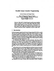
experimental results in Section 5. 2. RELATED WORK The proposed system consists of two parts: a method to generate a skill-based description of an assembly task and a method for robotic implementation of such a sequence of skills. As for the second part of the system, Henrich et al. introduced a set of contact states that enumerates all possible single contact situations between a DLO and a rigid convex polyhedron [Henrich99] and analyzed the possible transitions between these contact states [Remde99]; see Figure 1. Schlechter presented a library of macros for performing such transitions between contact states ("skill"), using an industrial robot equipped with a wrist-mounted force/torque sensor and detecting characteristic features in the force/torque signal for each skill [Schlechter01]. A demonstration video showing the execution of a robot program given such a sequence of skills can be found at [RESY01]. The first part of the proposed system can be considered a programming by demonstration (PbD) system. Ikeuchi et al. computed an assembly plan from visual observations of a human manipulation task [Ikeuchi92]. Onda et al. extracted a sequence of skills for manipulating rigid objects by observing a demonstration of the manipulation task with a master arm [Onda95]. Dillmann et al. presented a PbD system capable of E/V
E/F
N
E/E
V/E
V/ F
Figure 1: Enumeration of all possible contact state transitions. [Remde99]
work piece (DLO) are modeled in a 3D graphical simulation system. In the task N→N simulation step, the user moves the DLO by N p1 p2 N → V/F V/F means of a 6 DOF haptic device in a 3D V/F → V/F t V/E p3 graphical simulation and demonstrates the V/F → V/E → N δ1 assembly tasks to be automated to the δ2 δ3 system (e.g., establishing contact with face E: F: E F F and drawing over edge E). In the contact δ4 off-line state extraction step, the contact situation between the DLO and the environment on-line Transition detection Feature extraction Macro execution objects is observed over time (e.g., L(a,b,c,d) resulting in distances δ1, ..., δ4) and a TransferTo(p2); Transition(a,b,c,d,S): N_V/F(M, F): t sequence of contact states for the N_V/F(M1, F); α1Fx + ...+α6Mz TransferTo(p3); demonstrated assembly is derived (e.g., N, REPEAT V/F_V/E_N(M2, E); V/F, V/E, N). From this state sequence, the MoveS(∆M); UNTIL Transition(a,b,c,d,S); program generation step determines the Mi: Motion Direction necessary state transitions and relates them S = (α1 , ..., α6) t0 t with the involved geometric primitives ..., V/F→V/E→N). (e.g., N→N, Figure 2: Illustration of the overall process for programming and execution of Additionally, to obtain an executable sensor-based robot programs. program, a suitable library function has to be found for each state transition (e.g., monitoring a pick & place operation and mapping this operation TransferTo() for N→N) and supplied with the necessary to different target robots [Dillmann99]. Ehrenmann showed an parameters. These parameters include the goal positions of approach to extract user actions from a demonstration by fusion transfer motions (e.g., p2 or p3) or the motion direction and of visual data with force, position and orientation data obtained object orientation of assembly motions (e.g., M1 and F). from a data glove [Ehrenmann01a]. In [Ehrenmann01b], a During the on-line phase and the macro execution step, the system based on neural networks is presented, which classifies a generated program is executed by the robot control unit. The human demonstration (observed by a vision system and a data embedded sensor-based macros abstract from the sensors glove with tactile force sensors) in up to 16 different grasp types currently being used. The actually available robot sensors and three types of basic movements. Zöllner describes a multidetermine which library (providing the above mentioned macro sensor system that extracts fine motions (such as a screwing operations) is linked to the program. The feature extraction step action) [Zöllner02]. determines for each macro and its parameters with which sensor However, all of these methods monitor a real demonstration signal S and by which feature L(a,b,c,d) the state transition will performed in the physical world. This has the disadvantage of be detected. In the case of a force/torque sensor, the best linear requiring difficult image processing along with other sensor combination α1, ..., α6 of the three forces Fx, Fy, Fz and the three data acquisition and analysis. By working in virtual reality, we torques Mx, My, Mz determines the signal and a piecewise linear circumvent these difficulties. In this paper we focus on the function L(a,b,c,d) characterizes the possible features. Then, the extraction of a sequence of skills from a human demonstration robot moves in the prior fixed motion direction M until the performed in virtual reality. transition detection step observes a state transition at time t0. In summary, our method includes the programming and 3. SYSTEM CONCEPT control of robot manipulation tasks based on a basic set of robust, sensor-based, and reusable robot operations. For a more The task to program and control an industrial robot for detailed discussion, the off-line phase (first three steps above) is manipulation tasks can be divided into an off-line and an on-line subdivided into the following eight modules as shown in Figure phase. During the off-line phase, the users demonstrates the 3. manipulation tasks within an virtual environment. This The assembly motion is demonstrated by a human operator demonstration is used to automatically generate a sensorusing a 6 DOF input device with 3 DOF force feedback. The independent robot program, which is executed during the on-line system maintains position and orientation of a virtual gripper phase by an industrial robot using its specific sensors. Both of point, identified with the effect point of the 6 DFO input device. these phases are themselves subdivided into three steps (see The operator can monitor his action in a 3D graphical Figure 2). These steps are motivated in the off-line phase; the simulation. Both haptic input and 3D graphics are called user continuous user input is discretized first according to the interface in Figure 3. In the shape calculation module, we geometry (work piece states) and then according to the time calculate the shape, position and orientation of a gripped DLO (contact state transitions). In the on-line phase, this time- and based on a simple physical model. In this step, we calculate all state-discrete robot program is converted back into a continuous forces acting on the virtual gripping point. These forces result and therefore executable representation, first according the from contacts between the DLO and rigid world objects that are geometry (expected sensor signal curves) and then according the handled in the contact detection module. The forces are sent time (robot motions). The first three steps are discussed later in back to the haptic input device. In the same loop of calculating a full detail. The single steps are the following: shape, testing this shape for contact with world objects and During the off-line phase, the robot environment and the Task simulation
Contact state extraction δ(t)
Program generation
2
possibly recalculating a new shape, the 3D graphical representation of the virtual reality scene is updated. In the contact state detection module, all possible contact states between the DLO and the world object are determined, based on calculations done during contact detection. We use the contact state model described in Figure 1. Several uncertainties and ambiguities are resolved by taking into account the history of the assembly motion and by weighting different states against each other in the contact state selection module. The result is one well-known contact state best describing the current situation. In the state transition extraction module, the resulting sequence of contact states is compiled (combined) into a sequence of contact state transitions (called "skills"). The possible contact state transitions are shown in Figure 1. This sequence of contact state transition is further filtered and validated against constraints from the world model. This transition validation module eliminates unwanted transitions that can result from vibration while using the input device. Finally, based on the sequence of contact state transitions and geometrical information describing the world objects, a program is generated. The program contains both skill library calls and ordinary move and control instructions. The move instructions move the gripper somewhere near the point where a skill has to be executed. In addition, routines to deal with failed skill execution are added.
Task simulation
User Interface Position& Orientation
Force
Shape Calculation
Distance
Shape
Contact Detection
Contact State Detection
All Contact States
Contact State Selection
World Model
State extraction
Distance
Main Contact state
Program generation
State Transition Extraction
4. PROTOTYPE IMPLEMENTATION Currently, we implement a prototype in C++ language [Bonnermann02]. The software is build around a Phantom input device made by the US company Sensable. The haptic and graphical feedback is done using the GHOST software development kit shipped with the Phantom. In the current stage, the world objects are limited to convex polyhedrals, and the DLO is modeled as a piecewise linear function. Tests are done only with a one-piece DLO, which is effectively a rigid linear object (“RLO”). The contact detection is based on the GJK-algorithm [Cameron97] to fast compute distances between the RLO and the world objects. A series of two or three contact states is composed into one contact state transition, depending on what contact states are involved. The prototype emits these contact state transitions. Currently, we do not generate a real program.
Transition
Transition Validation
Filtered Transition
Programm Generation
Figure 3: Dataflow in the ViRop core
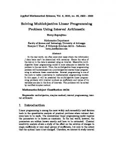
three contacts: with the top edge and back edge of the hole and with the surface of the left plate), (f) move down until the RLO lies on top of the left block. The detected contact states are listed in Table 1. Initially the RLO lies on top of world object number seven (E/F,7 = Edge of RLO has contact with Face of world object 7). After losing contact (N, contact state number 1 to 24), the left vertex of the RLO contacts the surface of the plate, world object numbers 3 to 6, in short V/F,4. The other rows of the table follow the motion description above in the same way. In the next step, these contact states must be combined into a sequence of contact state transition that could be executed by our online assembly system as shown in [RESY01]. While developing these test cases, some questions or problems have developed: first, it is very difficult to hold the Phantom “still”, as is necessary to achieve stable contacts that do not oscillate between state “N” (no contact) and some other state. Therefore, we need a powerful method to eliminate unwanted contact state transition. Second, it is sometimes difficult to decide which feature of an object should be used to calculate a contact state. This especially holds true for complex objects like our plate-with-hole. While teaching the move to the upper back corner of the hole (Figure 4d), the system repeatedly
5. EXPERIMENTAL RESULTS To test our system, we have created a small example scene as shown in Figure 4, consisting of a plate to the left, a block, and another plate with a hole in it. Additionally, there is a second block to the right, where our RLO is initially located. The task is to move the RLO through the hole and place it on top of the left block, while its left vertex touches the left wall. To do so, we taught the following sequence: (a) pick up the RLO, (b) move towards the plate-with-hole until the left vertex of the RLO touches the plate, (c) find the hole by moving across the surface until the surface is lost, to be in a known state, continue until the opposite edge of the hole is found, (d) move to the top of the hole, (e) move to the left of the scene until the left plate is touched by the left vertex of the RLO (in this situation we have
3
(a)
(b)
(c)
(d)
(e)
(f)
Figure 4: Screen shots of a demonstration of an example assembly task
detected an unstable E/E-l contact (that is, the long edge of the RLO is lined with some edge of an world object). Therefore, we need a better way to deal with composed world objects.
Index 0 1 24 25 37 38 39 52 53 76 77 87 88 90 91 97 98 102
State, Object E/F,7 N N V/F,4 E/F,4 E/F,4 N N E/F,5 E/F,5 E/F,5 & E/F,6 E/F,5 & E/F,6 V/F,1 & E/F,5 & E/F,6 V/F,1 & E/F,5 & E/F,6 V/F,1 & E/F,5 V/F,1 & E/F,5 V/F,1 & E/F,2 & E/F,5 V/F,1 & E/F,2 & E/F,5
Table 1 Generated contact states
[Ehrenmann01b] Ehrenmann M., Rogalla O., Zöllner R., Dillmann R.: "Teaching service robots complex tasks: Programming by Demonstration for Workshop and Household Environments”. Int. Conf. on Field and Service Robots (FSR), June 11-13 2001, Helsinki, Finnland, pages 397-402 [Hasegawa92] Hasegawa T., Suehiro T., Takase K.: "A model-based manipulation system with skill-based execution". In: IEEE Trans. on Robotics and Automation, vol. 8, no. 5, pp. 535-544, Oct. 1992. [Henrich99] Henrich D., Ogasawara T., Wörn H.: "Manipulating deformable linear objects – Contact states and point contacts". In: 1999 IEEE Int. Symp. on Assembly and Task Planning (ISATP'99), Porto, Portugal, July 21 - 24, 1999. [Ikeuchi92] Ikeuchi K., Suehiro T.: “Towards an Assembly Plan from Observation Part I: Assembly Task Recognition using Face-Contact Relations (Polyhedral Objects)”. In: Proc. of 1992 IEEE Int. Conf. an Robotics and Automation, Nice, France May 1992 [Morrow97] Morrow J. D., Khosla P. K.: "Manipulation task primitives for composing robot skills". In: Proc. of the IEEE Int. Conf. on Robotics and Automation (ICRA'97), Albuquerque, New Mexico, April 1997, pp. 3354-3359. [Onda95] Onda H., Hirukawa H., Takase K.: "Assembly motion teaching system using position/force simulator – Extracting a sequence of contact state transition". In: Proc. of the IEEE/RSJ Int. Conf. on Intelligent Robots and Systems (IROS'95), vol. 1, pp. 9-16, 1995. [Remde99] Remde A., Henrich D., Wörn H.: "Manipulating deformable linear objects – Contact state transitions and transition conditions". In: IEEE/RSJ Int. Conf. on Intelligent Robots and Systems (IROS'99), Kyongju, Korea, October 17 - 21, 1999. [RESY01] Henrich D., Schlechter A., Schmidt T., Yue S.: “Complete manipulation task of a leaf spring”. AVI-File (MPG4 encoded), http://resy.informatik.unikl.de/projects/RODEO/Files/manipulation_task_315.avi, 2001 [Schlechter01] Schlechter A., Henrich D.: "Manipulating deformable linear objects: Characteristics in force signals for detecting contact state transitions". In: 10th Int. Conf. on Advanced Robotics (ICAR'01), Budapest, 22.-25. August, 2001 [Zöllner02] Zöllner R., Rogalla O., Dillmann R., Zöllner M.: “Understanding Users Intention: Programming Fine Manipulation Tasks by Demonstration”. Submitted to: IEEE/RSJ Int. Conf. on Intelligent Robots (IROS02), September 2002
6. SUMMARY AND FUTURE WORK We have presented a system concept and prototypical implementation of a new approach for industrial robot programming. Based on previous work describing how to reliably execute manipulation tasks with sensor-based skills, our concept allows for intuitive and cost efficient programming of industrial robots, as the programmer does not require special knowledge about robot programming. While the current prototype is rather simple, first experiments with uncomplicated test cases have shown useful results. Further investigations of the program generation are required. Other questions include how to perform a more realistic simulation of the DLO and how to improve the contact state classification and contact state transition validation. REFERENCES [Bonnermann02] Bonnermann J.: "Virtuelle Roboter-programmierung: Entwurf eines Prototypen mit haptischem Eingabegerät". Master Thesis, Informatics Faculty, Universität Kaiserslautern, 2002 [Cameron97] Cameron S.:”Enhancing GJK: Computing Minimum and Penetration Distance between Convex Polyhedron”. Int. Conf. Robotics and Automation (ICRA97), Albuquerque, New Mexico, April 1997 [Dillmann99] Dillmann R., Rogalla O., Ehrenmann M., Zöllner R., Bordegoni M.: “Learning Robot Behaviour and Skills based on human demonstration and advice: the machine learning paradigm”. 9th Int. Symp. of Robotics Research (ISRR), October 9-12 1999, Snowbird, USA, pages 229-238 [Ehrenmann01a] Ehrenmann M., Knoop S., Zöllner R., Dillmann R.: „Multi Sensor Fusion Approaches for Programming by Demonstration”. Int. Conf. on Multi Sensor Fusion and Integration for Intelligent Systems (MFI), pages 227-232, August 19-22 2001, Baden-Baden, Germany
4