determining vehicle orientation of vehicles in images. We train a set of Histogram of Oriented Gradients (HOG) classifiers to recognize different orientations of ...
Visual Classification of Coarse Vehicle Orientation using Histogram of Oriented Gradients Features Paul E. Rybski and Daniel Huber and Daniel D. Morris and Regis Hoffman Abstract— For an autonomous vehicle, detecting and tracking other vehicles is a critical task. Determining the orientation of a detected vehicle is necessary for assessing whether the vehicle is a potential hazard. If a detected vehicle is moving, the orientation can be inferred from its trajectory, but if the vehicle is stationary, the orientation must be determined directly. In this paper, we focus on vision-based algorithms for determining vehicle orientation of vehicles in images. We train a set of Histogram of Oriented Gradients (HOG) classifiers to recognize different orientations of vehicles detected in imagery. We find that these orientation-specific classifiers perform well, achieving a 88% classification accuracy on a test database of 284 images. We also investigate how combinations of orientationspecific classifiers can be employed to distinguish subsets of orientations, such as driver’s side versus passenger’s side views. Finally, we compare a vehicle detector formed from orientationspecific classifiers to an orientation-independent classifier and find that, counter-intuitively, the orientation-independent classifier outperforms the set of orientation-specific classifiers.
I. I NTRODUCTION The ability to detect and track other vehicles automatically is a core requirement for any autonomous vehicle designed to operate in traffic. In order to plan a safe path through the environment, a vehicle needs to determine not just the location of other vehicles, but also their predicted trajectories. The orientation of a vehicle constrains its short term trajectory, and when the vehicle being tracked is in motion, it is relatively straightforward to estimate its orientation based on its direction of motion. The orientation of stationary vehicles, however, must be determined by other means. In this paper, we explore the ability of vision-based recognition algorithms to determine vehicle orientation from images. The problem of determining the orientation of stationary vehicles is important for autonomous vehicles, especially in urban environments. Stationary vehicles are encountered frequently, and an autonomous vehicle must be able to estimate whether a detected vehicle poses a potential hazard. A car sitting at the end of a driveway is much more likely to pull out into the street than a car parallel parked on the side of the street. The cars may be in the same location in both cases, but their orientation is the differentiating factor. Various technologies have been shown to be effective for detecting vehicles, including active sensors, such as LIDAR [1], [2], [3], and RADAR [4], [5], and passive sensors, such as cameras [6], [7]. Each sensing modality P. Rybski and D. Huber are faculty at The Robotics Institute at Carnegie Mellon University, Pittsburgh, PA, USA
{prybski,dhuber}@cs.cmu.edu D. Morris and R. eral Dyanmics Robotics
Hoffman Systems
are in
{dmorris,rhoffman}@gdrs.com
researchers at Pittsburgh, PA,
GenUSA
(a)
(b)
(c)
(d)
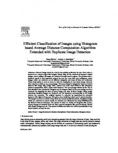
Fig. 1. The process by which the vision system described in this paper is used in concert with a LIDAR system. (a) First, a vehicle candidate is detected based on a LIDAR shape classification algorithm [2] (green lines). The projection of the 3D LIDAR points onto the image plane (blue lines) is calculated as a function of the estimated size/scale of the vehicle (plus some padding) and is then passed to the HOG classifier. (b) HOG features are extracted. (c) These features are passed to the vehicle detection algorithm and if a vehicle is detected (red lines), (d) it is passed through the bank of detectors to determine the orientation (purple lines and label).
has advantages and disadvantages. LIDAR and RADAR can identify moving objects by inferring (indirectly for LIDAR or directly for RADAR) the velocity of the surfaces that reflect the emitted energy. Stationary vehicles may be indistinguishable from a complex background and, thus, could not be identified as a vehicle until they started moving. At relatively close ranges, LIDAR can be used to detect stationary vehicles by fitting a model to the points returned, but such an approach will break down at longer ranges, where the limited angular resolution of the sensor will cause the points on the car to become much more sparse [8]. Computer vision algorithms can detect stationary vehicles in images at various ranges, orientations, and even under partial occlusion. Although the accuracy of vision-based methods is not yet high enough for practical application in autonomous vehicles, recent work has shown that contextual reasoning can offer improvements over brute force search over the entire image [9]. Unfortunately, such methods are not currently computationally efficient enough for autonomous vehicle applications. Our approach to stationary vehicle detection is to fuse information from LIDAR and vision-based sensing, thereby gaining the benefits of both modalities. The process is
illustrated in Figure 1. However, this paper focuses on the vision aspects of the overall algorithm. A 3D LIDAR-based algorithm, described separately in [2], is used to estimate the ground surface and identify regions of the scene containing objects sitting on the ground that are potential vehicles. These vehicle candidates are in the form of 3D cuboids encompassing the points for each contiguous region. The cuboids are then projected into the image from a camera that has been calibrated relative to the LIDAR, thereby identifying the approximate image location of the vehicle candidates. The vision-based algorithm then focuses its resources on those areas of the scene. Thus, the vision algorithm only needs to operate on a single candidate patch at a small set of scales set by the LIDAR-based detector. This greatly reduces the computation required and eliminates the need to handle the case where multiple cars must be distinguished in a single image patch. Vision is used to confirm whether or not a vehicle is at the location hypothesized by the LIDAR, and if so, then to determine the orientation of the target vehicle. In this paper, we focus on the use of vision-based algorithms to determine the orientation of vehicles in images. The general problem of vehicle detection in images has been studied extensively, but research on the more specific problem of determining vehicle orientation is fairly sparse [10]. In our work, we explore a detection algorithm based on a feature set called the Histogram of Oriented Gradients (HOG), which was first proposed by Dalal [11], [12], [13]. In Dalal’s formulation, the detector provides a binary output indicating whether a specific region of an image contains an instance of the desired object (in our case a vehicle). Each image passed into the detector is first converted into a set of gradients which are spatially discretized. A sub-image of a given size is extracted from this gradient histogram and converted into a feature vector (the HOG). This feature vector is then used as input to a binary support vector machine (SVM), and if the output exceeds a threshold, the object is detected at that location. This process is repeated at different offsets in the image and at multiple scales. A target object usually generates many detections at slightly different scales and offsets. Therefore, a mean-shift density estimation algorithm is used to combine these detections into a single bounding box location for a group of nearby detections. The chief contribution of this paper is a detailed investigation of how a set of HOG-based classifiers can be used to distinguish the orientation of vehicles in images. We explore how to create classifiers that are capable of determining individual orientations of vehicles as well as multiple orientations simultaneously. We also compare the effectiveness of a generic (orientation-independent) vehicle detector to a set of orientation-specific detectors. We conducted our analysis using a corpus of vehicle imagery extracted from publiclyavailable image databases, which we manually cropped and labeled with the vehicle orientation information.
imagery [6], [7], LIDAR [1], [3], and RADAR [4], [5]. In much of this work, the orientation of the vehicle is determined as part of the tracking process (e.g., the direction of motion indicates the front of the vehicle). Our approach is to develop a visual classification algorithm that can be used to augment and prime a LIDAR-based tracking algorithm. One advantage of a vision-based approach as opposed to a LIDAR-only approach is that it can be used to estimate the existence and orientation of vehicles that are immobile (such as parked cars) where a tracking-only approach would be unable to pick the vehicle out from an arbitrary background. Various combinations of features and classifiers can be applied to recognize a vehicle in an image. Several popular feature types have emerged in the literature, including Haar wavelets [14] [15] and Gabor filter outputs [16], both of which focus primarily on appearance; and edge templates [17], histogram of oriented gradients (HOG) [11] [18], edgelets [19], and shapelets [20], all of which focus primarily on shape. Shape- and appearance-based approaches are attractive because they operate on a single image and, as such, can be used to detect both moving and stationary objects. The discriminative power of shape-based features is generally considered to be stronger than that of appearancebased features. Within the class of shape-based algorithms, those that are derived from the HOG approach are considered one of the most accurate for visual classification problems. One notable example of the use of HOG is [10], where the algorithm has been used in concert with color features and explicit shape models, which demonstrates the ability to detect vehicles even in the presence of multiple occlusions. Our work uses only the HOG feature set to allow for operation on an autonomous vehicle. III. C LASSIFYING THE V ISUAL O RIENTATION OF V EHICLES For this study, we used eight orientations of vehicles with respect to the camera as shown in Figure 2. The orientations included: front (0 degrees), front-angle driver (45 degrees), side driver (90 degrees), rear-angle driver (135 degrees), side driver rear−angle driver
front−angle driver
rear
front
front−angle passenger
rear−angle passenger side passenger
II. R ELATED W ORK Research in vehicle tracking has been accomplished using a variety of different sensors including, but not limited to,
Fig. 2. The classifiers were trained to recognize views of cars from eight orientations. In this paper, we use the convention that the driver’s seat is on the left side of the vehicle.
Fig. 3. Examples of training images. Each row shows one viewpoint front (first row), front-angle driver (second row), side driver (third row), rear-angle driver (fourth row), and rear (fifth row).
rear (180 degrees), rear-angle passenger (225 degrees), side passenger (270 degrees), and front-angle passenger (315 degrees). Examples of these views are shown in Figure 3. Such coarse angles were used because it would be difficult to label training and evaluation instances at any higher resolution. Furthermore, this level of granularity is adequate for the task of determining whether a stationary vehicle is a potential hazard. The majority of the images used in this study were obtained from freely-available on-line sources, including Caltech 1011 , Caltech “Markus”2 , MIT3 , and Pascal VOC: 20054 . We collected additional images of specific vehicles as well. Statistics of the numbers of images in each category are shown in Table I. These datasets consist primarily of images of vehicles in urban settings. They contain a variety of vehicles, including compacts, sedans, trucks, vans, and SUVs. All of the imagery was taken outdoors in daylight, though the amount of light varied between the images (some were taken on clear days and others were taken on cloudy days). All images were taken from the ground (presumably by a person carrying a camera at head height). There was a wide variety of clutter found in each image, and the vehicles in the images were located at a wide range of distances from the camera as well. The images were cropped and scaled based on the manually determined bounding boxes. During testing, the classifiers were presented with image patches that contained the original cropped image plus upwards of 50% additional padding around the outside. We chose this approach for two reasons. First, we are interested in determining the 1 http://www.vision.caltech.edu/Image Datasets/Caltech101/101 objectCategories.tar.gz 2 http://www.vision.caltech.edu/Image Datasets/cars markus/cars markus.tar
orientation of vehicles, and less so in determining the existence or location of vehicles. Second, as described in the introduction, our method is designed to work in conjunction with a LIDAR-based cueing algorithm that identifies the image regions where potential vehicles exist. Furthermore, the range from the LIDAR provides a secondary source of scale information, allowing us to obtain a good approximation of the expected size of the potential vehicle in the image. The widths and heights of these training images were selected to provide a consistent boundary around the top/bottom and left/right side of the car in the image. Thus, the front and rear training examples were roughly square (50x60 pixels), the front-angle and rear-angle examples were wider (100x50 pixels), and the side examples were widest overall (130x50 pixels). The resulting images were divided into two sets: training and testing. In each trial, 90% of the instances in each category were randomly chosen for inclusion in the training set, and the remaining 10% served as the testing set. A set of images containing no vehicles was used as the base negative example training set. This set of images was obtained from the INRIA people dataset5 . In our experiments, we found that better performance for orientation-specific classifiers was achieved if we augmented this base negative example training set with positive instances of training examples from other orientations. For example, when training the front classifier, all of the positive examples from front-angle, side, rearangle, and rear were added to the negative training examples for the front classifier. The inclusion of the other views as negative examples for each orientation-specific classifier helps ensure that the underlying binary SVM learns the parameters of a hyperplane that maximizes the response to a specific orientation of the car while minimizing its response to the other orientations. Without the inclusion of the negative examples for different views, there is no way to ensure that the learned hyperplane does not also have a strong response to other orientations of the vehicle. Our orientation-specific vehicle detectors are based on Dalal’s HOG detection algorithm [13]. We based our implementation on the publicly available HOG detector software library, which we modified to support multiple instantiations of the detector. In order to compare the results of the different detector instances, we needed to normalize the raw output of the classifiers. An SVM is a maximum margin discriminator that maps a feature vector to a real number score whose value is designed to separate targets from clutter. In our multi-class task, we need to compare the output of multiple pair-wise discriminators (i.e., orientation-specific detectors). However, it is not meaningful to compare the scores of different SVM discriminators. If the output of a discriminator can be converted into a posterior probability, then Bayesian discrimination can be used to compare them to determine the best class among many. We chose to use Platt’s technique [21], which models the posterior probability
3 http://cbcl.mit.edu/projects/cbcl/software-datasets/cars128x128.tar.gz 4 http://pascallin.ecs.soton.ac.uk/challenges/VOC/download/voc2005 1.tar.gz,
http://pascallin.ecs.soton.ac.uk/challenges/VOC/download/voc2005 2.tar.gz
5 http://pascal.inrialpes.fr/data/human/INRIAPerson.tar
TABLE I T HE TOTAL NUMBER OF TRAINING AND TESTING IMAGES FOR EACH DATA SET. E ACH NEGATIVE TRAINING IMAGE IS BROKEN INTO SUB - IMAGES AND SAMPLED AT MULTIPLE SCALES TO CREATE
TABLE II C ONFUSION MATRIX FOR THE CLASSIFIERS TRAINED INDEPENDENTLY OF DRIVER / PASSENGER VIEW.
1000 S OF
NEGATIVE TRAINING SAMPLES PER IMAGE .
Actual front
Data set
# positive images 2292 82 538 269 269 936 468 468 388 194 194 348
all-sides front front-angle front-angle driver front-angle passenger side side driver side passenger rear-angle rear-angle driver rear-angle passenger rear
# negative images 648 1089 1033 1033 1033 995 995 995 1061 1061 1061 1058
# test images 250 42 58 29 29 104 52 52 42 21 21 38
front front-angle side rear-angle rear
of class Ci given data, D, as a sigmoid of the score: 1 P (Ci |D) = (1 + exp(a × s + b))
(1)
where s is the output score of the classifier, and a and b are parameters fit to a histogram of the scores (Figure 4). This is an approximation and depends on how well the sigmoid fits the data. Empirically, we found this simple model worked well in most cases we tested. Using these posterior estimates from the classifier scores, we selected the class with highest probability among all the classes for each feature vector.
Prob(Target|Data)
1 0.8 0.6 0.4 0.2 0
0
1
2
3
4 5 Classifier output
6
7
8
Fig. 4. Sigmoid function generated labeled data given to the all-sides classifier.
IV. E XPERIMENTAL R ESULTS We performed two specific studies for how the HOG classification algorithm could be used for identifying vehicles and their orientations. First, we evaluated the ability of the HOG classifier to recognize vehicles at different orientations assuming that a car was present in each image provided to the classifier. Second, we performed a detection-only study where we evaluated two different mechanisms for using the HOG classifier to detect the presence of a car in an image. A. Classification of Trained Car Orientations For the car orientation classification experiments, only the positive images (e.g. the images that actually contained
27 1 0 0 1
Predicted front- side rearangle angle 2 0 1 50 0 5 0 104 0 20 0 22 0 0 0
rear 12 2 0 0 37
vehicles) were shown to the classifiers. In these experiments, each image was shown to a set of different classifiers. The output responses from each of those classifiers were compared, and the maximum probability was chosen as the output. Confusion matrices were generated for a number of different training/testing scenarios. 1) Classification independent of driver/passenger view: The first experiment was performed with a set of classifiers trained on images containing both driver and passenger views. This scenario evaluated whether the classifiers can distinguish front from rear, and front-angle from rear-angle. The resulting confusion matrix for these classifiers is shown in Table II. Other views that had seemingly large confusion were the front-angle and the rear-angle. This is not entirely unexpected given that many vehicles have similar appearance from the front angles and from the rear angles. However, this particular set of classifiers was not necessarily ideal for real use because it was designed explicitly to be incapable of detecting the difference between the driver and passenger view of vehicles. Rather these were an initial experiment set up to see whether the specific angles, regardless of passenger or driver views, were readily distinguishable. One potential utility of these classifiers is discussed at the end of this paper. To address the more detailed question of distinguishing the passenger and driver views, a different set of view-dependent classifiers were developed and tested in the following sections. 2) Classification dependent of driver/passenger view: Second, an experiment was conducted where the front-angle, side, and rear-angle classifiers were all trained only on images that were from the driver view and then tested on images that only showed the driver view of the car. (Note: the front and rear data sets were the same as the first experiment, since driver and passenger view is meaningless to those views.) The resulting confusion matrix is shown in Table III. As can be seen from the confusion matrix, these driver view classifiers were much better at recognizing the difference between the front-angle and rear-angle views when shown driver view test images. This appears to be an example which illustrates that having a smaller variance in the types of images to be recognized creates a more accurate detector (as compared with the previous experiment). We then conducted an experiment to determine how well
TABLE III C ONFUSION MATRIX FOR THE CLASSIFIERS TRAINED ONLY ON DRIVER VIEWS AND TESTED ONLY ON IMAGES OF DRIVER VIEWS .
TABLE V C ONFUSION MATRIX SHOWING HOW CLASSIFIERS TRAINED ON THE SIDES OF VEHICLES FROM DRIVER AND PASSENGER VIEWS RESPONDED TO TEST IMAGERY FROM THE SAME CATEGORIES .
Actual front
front front-angle driver side driver rear-angle driver rear
Predicted side reardriver angle driver 1 1 1 0
28 0
frontangle driver 2 28
rear
Actual
10 0
side driver side passenger
0
0
51
1
0
0
0
0
20
1
1
0
0
0
37
TABLE IV C ONFUSION MATRIX SHOWING HOW CLASSIFIERS TRAINED ON FRONT- ANGLE AND REAR - ANGLE DRIVER AND PASSENGER VIEWS RESPONDED TO TEST IMAGERY OF THE SAME CATEGORIES .
Actual
front-angle driver front-angle passenger rear-angle driver rear-angle passenger
frontangle driver 29
Predicted frontrearangle angle passenger driver 0 0
rearangle passenger 0
0
29
0
0
0
0
21
0
0
0
0
21
the four angles could be differentiated from each other, as shown in the confusion matrix in Table IV. As can be seen, the four angle classifiers do very well in differentiating one view from the other regardless of whether the image of the car is from the front, the rear, or from driver or passenger views. The same test was performed with the side-views as shown in the confusion matrix in Table V. As can be seen, approximately 10% of the the driver-side images were misclassified as passenger-side. Certain vehicles are very symmetrical when viewed from the sides, which apparently can confuse the side detectors. A few of the driver views misclassified as passenger views can be seen in Figure 5. 3) Results of orientation-specific detectors: Finally, the complete set of eight orientation-specific classifiers was
Fig. 5. Several examples of vehicle side views that were misclassified as being the other side.
Predicted side side driver passenger 51 1 3
49
tested against all of the vehicle imagery. Figure 6 shows some results of the different orientation-specific classifiers on the test data. The confusion matrix showing the results of this experiment is shown in Table VI. From the table, we can see that the eight different side-and-orientation dependent classifiers are able to perform fairly well to identify the orientation of vehicles and achieved an accuracy of 88% correct over 284 test images. The reason for the non-symmetry between the driver and passenger sides is that the images chosen for training each classifier were selected at random from the full training set. Similarly, the test set was chosen at random so the various driver/passenger pairs for front-angle, side, and rear-angle, were not necessarily given the same (but mirrored) images to view. Vehicles typically have a great deal of symmetry between sides and potentially between the different angles which is a source of classification error. More experimentation is needed to determine whether the front detector’s errors in classification are caused by insufficient training data. The better results from the rear detector suggest that this may be the case. B. Detection of Vehicles The purpose for this research was to be able to classify the orientations of vehicles found in an image. However, in order to successfully do this, we are required to be able to detect the presence of a vehicle in the environment, regardless of its orientation. A simple way to do this would be to run all of the individual orientation-specific detectors over the image and return the union of their outputs. However, a question remained regarding the effectiveness of the different orientation-specific classifiers in general, due to the fact that they were fed negative imagery of the other orientations as part of their training set. One way to avoid this problem is to construct a single classifier to recognize vehicles in the image regardless of orientation. In this case, problems associated with negative imagery could potentially be avoided, as there would be no need to include this in the negative imagery. However, since views of vehicles from different angles, particularly front or rear vs. side, are so different, the question remained whether such a universal car detector would have poorer performance across vehicles in general. First, a classifier, called “all-sides”, was trained on all eight of the orientations of interest so that it would function as
TABLE VI C ONFUSION MATRIX FOR ALL ORIENTATION - SPECIFIC CLASSIFIERS .
Actual Front Front Front-angle (driver) Side (driver) Rear-angle (driver) Rear Rear-angle (passenger) Side (passenger) Front-angle (passenger)
Predicted Rear-angle Rear (driver) 0 10 0 0
26 0
Front-angle (driver) 1 26
Side (driver) 0 1
Rear-angle (passenger) 2 2
Side (passenger) 2 0
Front-angle (passenger) 1 0
0
0
50
1
0
0
1
0
0
0
0
18
0
0
0
3
1 0
0 0
0 0
0 0
37 0
0 21
0 0
0 0
0
0
3
0
0
2
47
0
0
0
0
4
0
0
0
25
ROC Curve for Detection 100
Front (1.00)
95
Front-angle driver (0.99)
Side driver (1.00)
Rear-angle driver (1.00)
True Positive Rate
90
85
80
Rear (0.44)
Rear-angle passenger (0.96)
75 allsides =0.318047 union =0.410791 70
Side passenger (0.31)
0
10
20
30
40 50 60 False Positive Rate
70
80
90
100
Front-angle passenger (1.00)
Fig. 6. Example results of the classifiers. Each image represents a view of a car that had the highest response from the corresponding classifier trained to recognize the view. Probability scores are shown in parenthesis under the image.
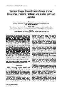
Fig. 7. An ROC curve for the performance of the two different classifiers for detecting the presence of vehicles rather than computing the orientation. A threshold value for each classifier, which corresponds to the value in the curve closest to the upper left of the graph, has been computed and is shown in the legend.
a generic car detector. A second classifier, called “union”, consisted of all eight orientation-specific classifiers. The detection threshold value for each classifier was chosen from an ROC curve computed on the training data as the point on the curve closest to the upper left corner. This is the threshold which will maximize the positive hit rate while keeping the false positive rate as low as possible. The overall classifier will report a detection if any of the individual classifiers exceed the detection threshold.
In these experiments, all of the test data described in the previous section were used as the positive examples. A set of negative examples four times the size of the positive set was used. Figure 7 illustrates the performance of the two different classifiers. As can be seen from the ROC curve, the single allsides classifier outperforms the union of the eight specific angle detectors. Not only is the all-sides classifier more accurate, but the runtime complexity is a fraction of the
allsides
front/rear
(0.94)
(0.98)
front
rear
driver
(0.97)
(1.00)
Fig. 9. image.
sides
angles
front−angle
passenger
rear−angle
driver
driver
passenger
passenger
A hierarchical method for searching for vehicle orientation in an
(1.00)
(1.00)
experiment was 8 times more than the all-sides classifier because of the need to re-run each of the 8 orientationdependent classifiers over the image. Thus, the all-sides classifier could be used first to identify the location of potential cars in the image. Then the individual angle classifiers could be used over those sub-patches, the size of which is smaller than the original search area, and greatly improve the time necessary to run the detector.
(1.00)
(1.00)
V. D ISCUSSION AND F UTURE W ORK
(0.85)
(1.00)
Fig. 8. Detection results from the “all-sides” classifier. From top to bottom are examples of front, front-angle (driver and passenger), side (driver and passenger), rear-angle (driver and passenger), and rear. Probability scores are shown in parenthesis under the image.
union classifier. The union classifier requires that the image be searched for responses to the HOG classifier 8 times, whereas the all-sides only requires a single search. Some of the results of the car detection algorithm are shown in Figure 8. In this experiment, multiple hits in a single image were possible (as evidenced in the top row of front-view images). However, only the hit with the maximum value was recorded and used. If the maximum value hit was in the wrong part of the image, the output was identified as a mis-classification. We speculate that including negative car views into the training sets for the orientation-specific classifiers in general caused those classifiers to have a lower response rate to the test imagery than the classifier trained on views from all views of the car. However, at this time, further evaluation and analysis is required to determine whether this hypothesis is correct, or if there is another effect that is causing the poorer performance of the individual orientation-specific classifiers for detecting the presence of vehicles in general. The strong performance of the all-sides classifier suggests a potential efficiency boost for the general use of this system. The required operating time for the union classifiers for this
In this paper, we have described a study in which we used a set of Histogram of Oriented Gradients (HOG) classifiers to determine the orientation of vehicles in images. We explicitly trained each classifier to recognize a different view of a vehicle using publicly-available datasets, which we hand-labeled and annotated. By running each of the different classifiers on an image of a vehicle and picking the maximum, our algorithm determined the correct orientation of the vehicle 88% of the time. We also determined that “merged-view” classifiers designed to detect only angles or only sides of the vehicle were also possible. In order to successfully train these classifiers, the negative image training set consisted of all of the views that the classifier was not meant to recognize. One challenge of determining the specific orientation of the vehicle using the HOG classifier approach still requires that the images be searched by multiple different classifier instances – one for each orientation of interest. Thus, for the problem described in this research, any implementation of the classifier would be slowed down by a factor of 8. However, because detectors can be created which encompass multiple views, such as the “all-sides” detector and the left/rightinvariant detectors described above, a binary-search approach for finding the vehicle orientation could be employed, as illustrated in Figure 9. Initially, a single generic view-independent vehicle detector (all-sides) would be used to locate potential vehicle candidates. This could additionally be run at a lower number of pyramid scales to speed up the overall process without sacrificing too much accuracy. Once a vehicle candidate is found, three more classifiers, front/rear detection, side detection, and all angles detection would be run, and the highest performing result would then proceed down the tree to further disambiguate the orientation. This hierarchical
R EFERENCES
Fig. 10. Plot of relative strengths of orientation detectors as vehicle moves between front and front-angle-driver views. Strength is measured as the length of the red bars in the angle graphs.
breakdown could potentially reduce the number of individual classifiers from eight (or nine if the all-sides classifier is used as an initial detector) to, at worst, four. Because there is a large potential for repeated/redundant operations in this algorithm, it may be possible to share the computation across classifiers to improve run-time efficiency. Our ongoing work is to fully integrate the visual classification algorithm with the LIDAR detector and tracker [2] in order to prune false positives from the set of potential trackable vehicles as well as to use the resulting orientation from the visual classifier to improve the state estimate of the tracked vehicle. Additionally, we are examining whether this approach can more accurately determine the actual angle of the vehicle (not just the angle of the strongest responding classifier) by comparing the relative responses of adjacent classifiers. An example of how the classifiers respond when presented with “in-between” data can be seen in Figure 10. ACKNOWLEDGEMENTS This work was sponsored by the Army Research Lab under contract: DAAD 19-01-2-0012. Thanks also to Navneet Dalal for making the core of his HOG classifier code available as well as providing useful additional insights through personal correspondence with the authors of this paper.
[1] A. Kirchner and C. Ameling, “Integrated obstacle and road tracking using a laser scanner,” in Proceedings of the IEEE Intelligent Vehicles Symposium, Darborn, MI, USA, 2000, pp. 675–681. [2] D. D. Morris, R. Hoffman, and P. Haley, “A view-dependent adaptive matching filter for ladar-based vehicle tracking,” in Proceedings of the 14th IASTED International Conference on Robotics and Applications, Cambridge, MA, USA, Nov 2009. [3] D. Streller, K. Furstenberg, and K. Dietmayer, “Vehicle and object models for robust tracking in traffic scenes using laser range images,” in Proceedings of the IEEE International Conference on Intelligent Transportation Systems, 2002, pp. 118–123. [4] M.-S. Lee and Y.-H. Kim, “An efficient multitarget tracking algorithm for car applications,” IEEE Transactions on Industrial Electronics, vol. 50, no. 2, pp. 397–399, 2003. [5] R. Mobus and U. Kolbe, “Multi-target multi-object tracking, sensor fusion of radar and infrared,” in Proceedings of the IEEE Intellgient Vehicles Symposium, 2004, pp. 732–737. [6] Z. Sun, G. Bebis, and R. Miller, “On-road vehicle detection: a review,” IEEE Transactions on Pattern Analysis and Machine Intelligence, vol. 28, no. 5, pp. 694–711, 2006. [7] C. Tzomakas and W. von Seelen, Vehicle Detection in Traffic Scenes using Shadows, IRINI 98-06. Ruhr Universitaet Bochum: Institut fuer Neuroinformatik, 1998. [8] C. Keat, C. Pradalier, and C. Laugier, “Vehicle detection and car park mapping using laser scanner,” in Proc of Intelligent Robots and Systems (IROS), 2005, pp. 2054–2060. [9] D. Hoiem, A. A. Efros, and M. Hebert, “Geometric context from a single image,” in International Conference of Computer Vision (ICCV), vol. 1. IEEE, October 2005, pp. 654 – 661. [10] Y. Li, L. Gu, and T. Kanade, “A Robust Shape Model for Multi-view Car Alignment,” in IEEE Computer Society Conference on Computer Vision and Pattern Recognition Workshops, 2009. CVPR Workshops 2009, 2009, pp. 2466–2473. [11] N. Dalal and B. Triggs, “Histograms of oriented gradients for human detection,” in IEEE Conference on Computer Vision and Pattern Recognition (CVPR), vol. II, June 2005, pp. 886–893. [12] N. Dalal, B. Triggs, and C. Schmid, “Human detection using oriented histograms of flow and appearance,” in European Conference on Computer Vision (ECCV), vol. II, May 2006, pp. 428–441. [13] N. Dalal, “Finding people in images and videos,” Ph.D. dissertation, Institut National Polytechnique de Grenoble, July 2006. [14] C. Papageorgiou and T. Poggio, “A trainable system for object detection,” International Journal of Computer Vision, vol. 38, no. 1, pp. 15–33, 2000. [15] P. Viola, M. J. Jones, and D. Snow, “Detecting pedestrians using patterns of motion and appearance,” International Journal of Computer Vision, vol. 63, no. 2, pp. 153–161, 2005. [16] H. Cheng, N. Zheng, and J. Qin, “Pedestrian detection using sparse gabor filters and support vector machine,” IEEE Intelligent Vehicle Symposium, pp. 583–587, 2005. [17] D. M. Gavrila, J. Giebel, and S. Munder, “Vision-based pedestrian detection: The protector system,” IEEE Intelligent Vehicle Symposium, pp. 13–18, 2004. [18] Q. Zhu, S. Avidan, M. Yeh, and K. Cheng, “Fast human detection using a cascade of histograms of oriented gradients,” in IEEE Conference on Computer Vision and Pattern Recognition (CVPR), 2006, pp. 1491– 1498. [19] B. Wu and R. Nevatia, “Detection of multiple, partially occluded humans in a single image by bayesian combination of edgelet part detectors,” International Journal of Computer Vision, vol. 1, pp. 90– 97, 2005. [20] P. Sabzmeydani and G. Mori, “Detecting pedestrians by learning shapelet features,” Conference on Computer Vision and Pattern Recognition, 2007. [21] J. Platt, “Probabilistic outputs for support vector machines and comparison to regularized likelihood methods,” in Advances in Large Margin Classifiers, A. Smola, P. Bartlett, B. Sch¨olkopf, , and D. Schuurmans, Eds., Cambridge, MA, 2000.