of the robot, camera parameters as well as different levels of calibration between ...... ing and grasping of a moving object with a robotic hand-eye system', IEEE.
VETENSKAP OCH KONST
KUNGL TEKNISKA HÖGSKOLAN
Department of Numerical Analysis and Computing Science TRITA-NA-P02/01 � ISSN 1101-2250 � ISRN KTH/NA/P--02/01--SE � CVAP259
Survey on Visual Servoing for Manipulation Danica Kragic and Henrik I Christensen
Report from Computational Vision and Active Perception Laboratory (CVAP)
Survey on Visual Servoing for Manipulation Danica Kragic and Henrik I Christensen Centre for Autonomous Systems, Numerical Analysis and Computer Science, Fiskartorpsv. 15 A 100 44 Stockholm, Sweden {danik, hic}@nada.kth.se Technical report ISRN KTH/NA/P-02/01-SE
Contents 1 Abstract
3
2 Introduction
4
3 Background
5
4 Categorization
8
5 Visual-Motor Model Estimation 5.1 A-priori Known Models (Calibrated Models) 5.1.1 Position based control . . . . . . . . 5.1.2 Image based control . . . . . . . . . 5.1.3 2 1/2D visual servoing . . . . . . . . 5.2 Visual-Motor Model Estimation . . . . . . .
. . . . .
10 11 11 16 24 25
6 Obtaining Visual Measurements 6.1 Monocular Vision . . . . . . . . . . . . . . . . . . . . . . . . . . 6.2 Binocular Vision . . . . . . . . . . . . . . . . . . . . . . . . . . 6.3 Redundant Camera Systems . . . . . . . . . . . . . . . . . . . .
27 28 31 34
7 Control Generation and System Design
35
8 Visually Guided Systems - A Summary
36
9 Discussion
40
2
. . . . .
. . . . .
. . . . .
. . . . .
. . . . .
. . . . .
. . . . .
. . . . .
. . . . .
. . . . .
1 Abstract Vision guided robotics has been one of the major research issue for more than three decades. The more recent technological development facilitated the advancement in the area which has resulted in a number of successful and even commercial systems using off–the–shelf hardware. The applications of visually guided systems are many: from intelligent homes to automotive industry. However, one of the open and commonly stated problems in the area is the need for exchange of experiences and research ideas. In our opinion, a good starting point for this is to advertise the successes and propose a common terminology in form of a survey paper. The paper concentrates on different types of visual servoing: image based, position based and 2 1/2D visual servoing. Different issues concerning both the hardware and software requirements are considered and the most prominent contributions are reviewed. The proposed terminology is used to introduce a young researcher and lead the experts in the field through a three decades long historical field of vision guided robotics. We also include a number of real–world examples from our own research providing not only a conceptual framework but also illustrating most of the issues covered in the paper.
3
2 Introduction Using visual feedback to control a robot is commonly termed visual servoing, (Hutchinson et al. 1996). Visual (image based) features such as points, lines and regions can be used to, for example, enable the alignment of a manipulator / gripping mechanism with an object. Hence, vision is a part of a control system where it provides feedback about the state of the environment. Visual servoing has been studied in various forms for more than three decades starting from simple pick– and–place tasks to todays real-time, advanced manipulation of objects. In terms of manipulation, one of the main motivations for incorporating vision in the control loop was the demand for increased flexibility of robotic systems. One of the open and commonly stated problems in the area is the need for exchange of experiences and research ideas.
Initialization
Tracking
Initialization
Robot Control Robot Control
VISUAL SERVOING
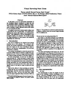
Figure 1: left) Open–loop robot control: Initialization represents the extraction of features used to directly generate the control sequence (robot motion sequence) no on–line interaction between the robot and the environment exist, and right) Major components of a visual servo system: Initialization (visual servoing sequence is initialized), Tracking (the position of features used for robot control are continuously updated during the robot/object motion), Robot Control (based on the sensory input, a control sequence is generated). A closed–loop control of a robot system, where vision is used as the underlying sensor, usually consists of two interwined processes: tracking and control, see Figure 1 (right). Tracking provides a continuous estimation and update of features during the robot/object motion. Based on this sensory input, a control sequence is generated. In addition, the system may also require an automatic initialization which commonly includes figure–ground segmentation and object recognition. As mentioned earlier, visual servoing has been studied for more than three decades. More recently, the area has attracted significant attention as computa4
tional resources have made real-time deployment possible. At the same time, robust methods for real-world scenarios have gradually enabled progress on realistic problems in terms of complexity. A problem that has become apparent with the increase in the number of contributions to visual servoing is a lack of a terminology and taxonomy for the approaches presented. Visual servoing is used in a rich variety of applications such as lane tracking for cars, navigation for mobile platforms and manipulation of objects. The most general of these applications is manipulation of objects which requires detection of objects, segmentation, recognition, servoing, alignment, grasping. Although many approaches do not address all of these aspects, the manipulation task provides a global framework for consideration of the diverse research on servoing. The literature contains an excellent introduction to visual servoing in form of a tutorial by (Hutchinson et al. 1996). The tutorial is however five years old by now and significant work has been reported since then. In addition, there is a lack of a survey of the vast literature available. Consequently, in this paper a comprehensive survey of the literature is provided. As the basis for the presentation, a taxonomy of approaches to visual servoing is defined and the key factors influencing visual servoing are identified. The various approaches to visual servoing are illustrated by examples that primarily are taken from our own research. The remainder of the survey starts with a Section 3 that provides an introduction to visual servoing mainly outlining the history and major milestones in the development of visual servoing techniques from its very beginning. From this, the major steps involved in servoing are introduced in Section 4. Each of the steps are then outlined: i) approaches to visual-motor estimation in Section 5, ii) strategies to feature/state estimation in Section 6, and iii) methods for control generation in Section 7. These three steps provide the basic dimensions in our taxonomy for visual servoing. The literature is then reviewed and the presented approaches are classied and discussed in relation to the proposed taxomony 8. The final section provides a discussion on the open issues and trends in the field of visual servoing.
3 Background The following distinction is usually made between two different ways of using visual information in a robot system:
�
Open–loop Robot Control Extraction of image information and control of a robot are two separate tasks where at first image processing is performed followed by the generation of a control sequence, (see Figure 1, left). A typical example is to recognize the object to be manipulated by matching image features to a geometrical model of the object and compute its position and orientation (pose) relative to the camera (robot) coordinate system. This absolute pose, Cartesian– space information is used to move the robot to the desired pose relative to the object. To estimate the pose of the object, the model of the object must be 5
available. To move the robot based on the visual information extracted in the camera frame, the camera(s) has to be calibrated with respect to the robot. In addition, the robot direct and inverse kinematic models have to be available to convert Cartesian–space robot positions into joint–space configurations. The robot can then execute the task by performing “blind” movements which assumes that the environment remains static after the robot has started to move (open–loop approach).
�
Visual Servoing In 1979, Hill and Park, (Hill & Park 1979) introduced the term visual servoing to distinguish their approach from earlier work. In 1980 the following taxonomy of visual servo systems was introduced in (Sanderson & Weiss 1980): 1. Dynamic look-and-move systems: These systems perform the control of the robot in two stages: the vision system provides input to robot controller that then uses joint feedback to internally stabilize the robot. As pointed out by (Hutchinson et al. 1996) nearly all of the reported systems adopt this approach. 2. Direct visual servo systems1 : Here, visual controller directly computes the input to the robot joints and robot controller is eliminated.
A typical visual servoing task usually includes some form of i) “positioning” such as aligning the robot/gripper with the target, or ii) “tracking” or remaining a constant relationship between the robot and the moving target. In both cases, image information is used to measure the error between the current location of the robot and its reference or desired location. Image information used to perform the task is either i) two dimensional expressed by using image plane coordinates, or ii) three dimensional where camera/object model is employed to retrieve pose information with respect to the camera/world/robot coordinate system. So, the robot is controlled either using image information as two- or three dimensional which classifies the visual servo systems additionally as: 1. Position-based visual servo systems These systems retrieve the three-dimensional information about the scene where known camera model (usually in conjunction with a geometric model of the target) is used to estimate the position and the orientation (pose) of the target with respect to the camera (world, robot) coordinate system. The positioning or tracking task is defined in the estimated (3D) pose space. 2. Image-based visual servo systems Here, 2D image measurements are used directly to estimate the desired movement of the robot. Typical tasks like tracking and positioning are performed 1 This term is adopted from (Hutchinson et al. 1996). Sanderson and Weiss used the term visual servo for this type of systems but that introduces a certain confusion since the term has been widely used for all types of closed–loop vision based control systems.
6
by reducing the image distance error between a set of current and desired image features in the image plane. 3. 2 1/2 D visual servo systems Here, a combination of previous two approaches is used and the error to be minimized is specified both in the image and in the pose space. Hence, the general idea behind visual servoing is to derive the relationship between the robot and the sensor space and estimate a velocity screw associated with the robot frame needed to minimize the specified error. Visual servoing borrows from many different research areas including robot modeling (geometry, kinematics, dynamics), real–time systems, control theory, systems (sensor) integration, computational vision (image processing, structure– from–motion, camera calibration). As pointed out in (Corke 1994), there are many different ways of classifying the reported results: based on sensor configuration, number of cameras used, generated motion command (2D,3D), scene interpretation, underlying vision algorithms. Given the vast amount of published material within and across different research areas, the next section proposes a common taxonomy. The proposed taxonomy is used to reference a number of contributions regarding visual servoing.
task space
T
y*
ROBOT
CONTROL GENERATION
TASK PLANNING
u 3D WORLD
y
STATE ESTIMATION
sensor space
x
S
Figure 2: The major processes involved in a vision based control of a robot. A relative Euclidian motion of the robot is defined as the input u in the task space of the robot, T . x represents the state vector, y is the measurement vector and y� is the vector of desired measurements in the sensor space, S .
7
4 Categorization Let us assume, according to Figure 2, a robotic system that operates in a 3D world. The relative Euclidian motion of the robot is produced by the input u in its task space, T . Since, in our context, T represents the set of all poses that the robot’s end–effector can attain, it is denoted by TG � SE(3). If the robot is controlled using six-degree Cartesian velocity representation, the control input vector is u = [VX VY VZ ωX ωY ωZ ℄T 2 R (6), the velocity screw of the robot. The state vector, x, may, for example, represent the pose of the target, X = [R; t℄, usually represented by translation and rotation parameters, q = [tX tY tZ φ ψ γ℄T 2 R (6). The measurement vector y may, for example, contain the pose of the target or image point coordinates, y = [ [x1 y1 ℄; :::[xk/2 yk/2 ℄ ℄T 2 R (k) while y� represents the vector of desired measurements. A visual servoing task is also referred to as a task function, (Chaumette et al. 1991) or a control error function. Representing some desired set of features by y� and the set of current features with y, the objective of visual servoing is to regulate the task function to zero. When the task is completed, the following holds: e(y�
y) = 0:
(1)
The task function is also referred to as kinematic error function or virtual kinematic constraint in the case of position based visual servoing and image error function in the case of image based visual servoing, (Hutchinson et al. 1996). For the discussion, the research issues are divided into three parts:
�
�
Visual-Motor Model Estimation (Corke & Good 1996) make a distinction between visual kinematic and visual dynamic control where the former deals with how a manipulator should move in response to the perceived visual information, while the latter approach accounts for the dynamic effects that usually occur in a robotic system. Accordingly, the basic concern here is to classify systems based on the estimation of visual-motor model, see Figure 4: i) systems where visualmotor model is known a–priori, or ii) estimated2 . State Estimation Here, the issues related to visual measurements are addressed: camera configuration, number of cameras and commonly adopted image processing techniques. Visual measurements define the extraction of visual information such as optical flow, position and orientation of an object or features like points or lines. The following sensor-robot configurations may be employed: eye–in–hand, stand alone (fixed) camera system or their combination, see Figure 3. The estimation may be performed in image space (2D)
2 The
further division of the former systems to position, image or 2 1/2D based is just for the simplicity reasons. This does not exclude the issue that the latter systems will also use one of these approaches during the control of the robot.
8
and used together with camera model to retrieve the 3D information. For systems that utilize image (2D) information directly, the task function is normally also defined in image space. However, this is not the case in general for systems that compute the complete 3D pose of the target where the task function may be expressed both in 2D or in 3D.
�
Control Generation Control synthesis is closely related to the first issue, visual-motor model estimation. The accuracy of the model will directly affect the rate of convergence of the system. In this section, some of the work related to the underlying control design is briefly reviewed. In the next section, visual servo systems are categorized with respect to the estimation of the visual–motor model, see Figure 4. For the systems where the geometry or kinematics of the manipulator is known and used in the servoing process, it is assumed that the visual–motor model is known a– priori. Depending on the accuracy of the model and the specification of the task the systems are additionally divided into position, image and 2 1/2D based systems. The other group of systems estimate the visual–motor model either analytically or by learning.
CAMERA−ROBOT CONFIGURATION number of cameras
1 EYE−IN−HAND
VM1
2
STAND−ALONE
VM2
EYE−IN−HAND
VM3
VM4
>2 STAND−ALONE
VM5
Figure 3: Camera–robot configurations used in visual servoing control (from left to right): VM1 monocular eye–in–hand, VM2 monocular stand–alone, VM3 binocular eye–in–hand, VM4 binocular stand–alone and VM5 redundant camera system.
9
VISUAL−MOTOR MODEL ESTIMATION
KNOWN A−PRIORI
POSITION BASED
2 1/2D
ESTIMATED
IMAGE BASED ANALYTICALLY BY LEARNING
Figure 4: Visual servo systems with respect to the visual–motor model estimation. Systems where visual-motor model is known a priori use the kinematic model of the robot, camera parameters as well as different levels of calibration between the camera and the robot system to estimate the desired robot motion. On the other hand, there are systems that estimate visual-motor model either by learning or analytically, allowing for the control without the knowledge of the robot geometry.
5 Visual-Motor Model Estimation To classify systems according to the estimation of visual-motor model, the taxonomy as presented in Figure 4 and Figure 5 is adopted. If the robot forward or inverse kinematics are known, the differential changes between the joint and Cartesian space are computed using robot Jacobian. These systems are classified as systems where visual-motor model is known a-priori. Depending on the feedback representation mode and level of calibration between the camera and the robot frame, the visual servo systems are classified as position based, image based or 2 1/2 D systems. Most of the early visual servo systems relied on a accurate calibration of the system and performed tasks using the position based approach. Since the process of calibration could be tedious, error prone or even impossible to perform, approaches that avoid the calibration step or where a some knowledge of the calibration is sufficient, became appealing. Hence, image based servo systems are usually preferred to position based systems since they may carry out the task without the accurate calibration. However, some knowledge of the transformation between the sensor and the robot frame is still required. On the other hand, there are systems that completely obviate the calibration step and estimate the visual-motor model either on– or off–line. The visual-motor model may be estimated: a) analytically (nonlinear least square optimization) or b) by learning or training. In addition, as presented in Figure 5, the systems may estimate an image Jacobian and use the known robot model or a coupled robotimage Jacobian may be estimated.
10
Coupled Image−Robot Jacobian
JOINT SPACE
CARTESIAN SPACE
IMAGE PLANE
Image Jacobian
Robot Jacobian
Figure 5: Some of the visual servo systems use the knowledge of robot kinematics (robot Jacobian) and then the image Jacobian relates the differential changes between image features and the robot’s Cartesian velocities or incremental pose changes. On the other hand, a coupled robot-image Jacobian relates the differential changes between the robot joints and image features.
5.1 A-priori Known Models (Calibrated Models) As already mentioned, we classify visual servoing approaches based on the feedback representation mode. These can be: i) position based, ii) image based and iii) 2 1/2 D visual servo systems. We now present the basic ideas and discuss the characteristics of each of them. 5.1.1
Position based control
Position based visual servoing is usually referred to as a 3D servoing control since image measurements are used to determine the pose of the target with respect to the camera or some common world frame. The error between the current and the desired pose of the target is defined in the task (Cartesian) space of the robot. Hence, the error is a function of pose parameters, e(X). Two examples of position based servoing are presented in Figure 6. The figure on the left shows an example where the camera is controlled from its current pose, C XO , so to achieve the desired pose with respect to the object, C X�O . In this example, the camera is attached to the last link of a manipulator and observes a static or a moving target, and the model of the object is used to estimate its pose. The figure on the right shows an example of a static camera and a moving object. It is assumed here that the object is held by a manipulator which is then controlled to, again, achieve the desired pose between the object and the camera. Since the pose of the object is estimated relative to the camera, the transformation between the robot and the camera has to be known to generate the required motion of the manipulator. These examples demonstrate two main reasons why the position based visual servoing is usually not adopted for servoing tasks: i) it requires the estimation of the pose of the target or which requires some form of a model, and ii) to estimate
11
cX
o
c
X
X
Xo X
Z
Z
Z X
Y
Z
Y
Y
Y
c * Xo
c * Xo
X
Z
Y
X
Y
Z
Figure 6: Two examples of position based visual servoing control: left) an example of an eye–in–hand camera configuration where the camera/robot is servoed from the C XO (current pose) to the C X�O (desired pose), and right) a monocular, stand– alone camera system used to servo a robot held object from its current to the desired pose. the desired velocity screw of the robot and in order to achieve accurate positioning, it requires precise system calibration (camera, camera/robot). A block diagram of the position based visual servoing approach is presented in Figure 7. Here, the difference in pose between the desired and the current pose represents an error which is then used to estimate the velocity screw for the robot, q˙ = [V; Ω℄T , so to minimize the error. An Example: Align and track task Let us assume that the task is to first achieve and maintain a constant pose between the object and robot end–effector, O X�G . According to (Hutchinson et al. 1996), this o * Xc
POSITION (CARTESIAN)
+ o
Xc
−
V, Ω ROBOT
BASED CONTROL
3D POSE ESTIMATION
FEATURE EXTRACTION
CAMERA
Figure 7: A block diagram of the position based visual servoing: the pose of the target is estimated, C XO and compared to the reference (desired) pose, C X�O . This is then used to estimate the velocity screw, q˙ = [V; Ω℄T , for the robot so to minimize the error.
12
is considered as an EOL (endpoint open loop) system, since only the target object is observed during the servoing sequence. R
XG
R
* XG O
* XG
O
C R
XG
XO
XC
Figure 8: Relevant coordinate frames and their relationships for the “Align–and– track” task where a stand–alone camera system is used to guide the robot to the desired pose with respect to the object. Here, O X�G represents the desired pose between the object and the end–effector while O XG represents the current (or initial) pose between them. To perform the task using the position based servoing approach, the transformation between the camera and the robot coordinate frames, C X , has to be known. The pose of the end-effector with respect to the robot base R system, R XG is known from the robot’s kinematics. The manipulator is controlled in the end-effector frame. According to Figure 8, if O XG = O X�G then R XG = R X�G . The error function to be minimized may then be defined as the difference between the current and the desired end-effector pose: t�G
∆ R tG = R tG
R
∆ R θG = R θG
R
θ�G
(2)
Here, R tG and R θG are known from the forward kinematics equations and R t�G and have to be estimated. The homogeneous transformation between the robot and desired end–effector frame is given by:
R θ� G
R
X�G = R XC C XO O X�G
(3)
The pose between the camera and the robot is estimated off–line 3 and the pose of the object relative to the camera frame is estimated using the model based tracking 3 The homogeneous transformation relating the camera and the robot coordinate frames was obtained off–line. A LED was placed at the end of the manipulator chain and its position in the image was estimated while the manipulator moved through a number of predefined points. Assuming the knowledge of the camera intrinsic parameters, the pose estimation approach presented in (Kragic 2001) was used to estimate the transformation between the robot and the camera.
13
Figure 9: A sequence from a 6DOF visual task: From an arbitrary starting position (upper left), the end–effector is controlled to a predefined reference position with respect to the target object, (upper right). When the object starts moving, the visual system tracks the pose of the object. The robot is then controlled in a position based framework to remain a constant pose between the gripper and the object frame. system presented in (Kragic 2001). Expanding the transformations in (Eq. 3) we get: R � ˆ O O t�G + R RC C ˆtO + R tC (4) tG = R RC C R ˆ O and C ˆtO represent predicted values obtained from the tracking algowhere C R rithm. Similar expression can be obtained for the change in rotation by using the addition of angular velocities (see Figure 8) and (Craig 1989): R
ˆ O + R RC C R ˆ O O Ω�G Ω�G = R ΩC + R RC C Ω
(5)
ˆ O are slowly varying functions of time, integration Assuming that the R RC and C R � R of ΩG gives (Wilson et al. 1996): R
ˆ O O θ�G θ�G t R θC + R RC C θˆ O + R RC C R
(6)
Substituting (Eq. 4) and (Eq. 6) into (Eq. 2) yields: ∆ R tG = R tG
∆ R θG t R θG
R
tC
R
θC
R
RC C ˆtO R RC C θˆ O
14
R
ˆ O O t�G RC C R R ˆ O O θ�G RC C R
(7)
which represents the error to be minimized: �
e=
∆ R tG ∆ R θG
�
(8)
After the error function is defined, a simple proportional control law is used to drive the error to zero. The velocity screw of the robot is defined as4 : q˙ t Ke
(9)
By using the estimate of object’s pose and defining the error function in terms of pose, all six degrees of freedom of the robot are controlled. A few example images obtained during one of the experimental sequences are shown Figure 9. From an arbitrary starting position, the end–effector is moved to a predefined stationing pose with respect to the target object (first row, left). When the object starts to move, the visual system estimates its pose, C XO . The error is estimated according to (Eq. 8) and used to estimate the velocity screw of the robot using (Eq. 9). In general, the main advantage of this approach is that the camera/robot trajectory is controlled directly in the Cartesian coordinates. This allows easier trajectory planning for e.g., obstacle avoidance. However, especially in the case of eye–in– hand camera configuration, image features used for pose estimation may get out of the image. The reason is that the control law does not incorporate any constraints when it comes to image plane feature coordinates. If the camera is only coarsely calibrated (i.e., the camera parameters are approximately known), the current and desired camera poses will not be accurately estimated which will thus lead to a poor performance (in terms of accuracy) or even a complete failure of the visual servoing task. One of the solutions to this problem is to design the servo system as an endpoint closed loop system where both the target and the end–effector are observed during the execution of the task (Hutchinson et al. 1996). There are examples of utilizing both eye-in-hand and stand-alone camera configurations for position based control. The examples range from planar positioning systems (Allen et al. 1993), to systems that use object models and demonstrate full pose determination in real–time, see for example (Wilson et al. 1996), (Wunsch & Hirzinger 1997) and (Drummond & Cipolla 1999b). An extensive evaluation of the position based visual servoing with respect to trade–offs between the requirements of speed, accuracy and robustness is given in (Wilson et al. 2000). Since most of the reported systems adopting this approach concentrate on the extraction of the visual information rather than on the analysis of sensitivity, etc., we provide additional references in Section 6. The section also provides a number of pointers related to the pose estimation problem, structure– from–motion, and stereo reconstruction problems.
15
f3*
f2*
f4*
f1* c
c
X
f3
f4
c
f2 c f1
Z Y
Oc
Figure 10: An example of image based visual servoing. Let us assume a case of a static camera and a robot holding the object. A number of feature points on the object is tracked and used to generate a vector of current measurements, fc . The vector of reference measurements is denoted f� . The error function is defined as a function of distance between these measurements, e = fc f� . This error function is then updated in each frame and used used together with the image Jacobian to estimate the control input to the robot. 5.1.2
Image based control
Image based visual servoing involves the estimation of the robot’s velocity screw, ˙ so as to move the image plane features, fc , to a set of desired locations, f� , (Hager q, et al. 1995), (Malis et al. 1998), (Chaumette et al. 1991). Image based visual servoing control involves the computation of the image Jacobian or the interaction matrix, (Hutchinson et al. 1996), (Espiau et al. 1992), (Hashimoto & Noritsugu 1998). The image Jacobian represents the differential relationship between the scene frame and the camera frame (where either the scene or the camera frame is usually attached to the robot): 2 h
J (q) =
δf δq
i
6 4
=6
δ f1 (q) δq1
.. .
δ fk (q) δq1
:::
..
.
:::
δ f1 (q) δqm
.. .
δ fk (q) δqm
3 7 7 5
(10)
where q represents the coordinates of the end-effector in some parameterization of the task space T , f [ f1 ; f2 ; :::; fk ℄ represents a vector of image features, m is the dimension of the task space T and k is number of image features. The relationship between a velocity screw associated to the manipulator and the image parameters rates of change is given by: ˙f = J q˙ (11) 4 It
is straightforward to estimate the desired velocity screw in the end–effector coordinate frame.
16
Using a classical perspective projection model with unit focal length, the relationship between an image point velocity and a 3D velocity screw is given by: �
x˙ y˙
�
� 1 =
Z
0
0 1 Z
x Z y Z
xy (1 + y2 )
(1 + x2 )
xy
y x
�
q˙
(12)
where Z represents the 3D distance of the point with respect to the camera. Image based visual servo systems express the control error function directly in 2D image space. If image positions of point features are used as measurements, the error function is defined simply as a difference between the current and the desired feature positions: (13) e(f) = fc f� The most common approach to generate the control signal for the robots is the use of a simple proportional control 5 (see (Papanikolopoulous & Khosla 1993) and (Hashimoto, Ebine & Kimura 1996) for an optimal control approach): u = q˙ = KJ† e(f)
(14)
where J† is the (pseudo-)inverse of the image Jacobian and K is a constant gain matrix. Figure 10 shows an example of an image based visual servoing approach where it is assumed that the camera is static and that it observes the robot holding an object. A number of feature points on the object are tracked and used to generate a vector of current measurements, fc . The vector of reference measurements is denoted f� . The error function is defined as a function of distance between these measurements according to (Eq. 13). This error function is then updated in each frame and used together with the image Jacobian to estimate the control input to the robot using (Eq. 14). The vector of reference measurements, f� , is usually generated using a so called “teach by showing” approach where the robot is first moved to a desired position and the image coordinates of feature positions are recorded. After that, the robot is moved to some other, initial position and visual tracking is initiated. In a closed– loop manner, the robot is controlled while moving to the desired or “taught” position while tracking the features and estimating fc . In (Horaud et al. 1998), the desired position between the gripper and an object is defined through a projective representation and the new goal image is computed when the target changes instead of being learnt manually. According to (Eq. 12), the estimation of the image Jacobian requires knowledge of the camera intrinsic and extrinsic parameters. Extrinsic parameters also represent a rigid mapping between the scene or some reference frame and the camera frame. If one camera is used during the servoing process, the depth information needed to update the image Jacobian is lost. Therefore, many of the existing systems usually rely on a constant Jacobian which is computed for the desired 5 With
an assumption that the target is motionless.
17
camera/end–effector pose. This is one of the drawbacks of this approach, since the convergence is ensured only around the desired position. This problem may be solved by adaptive estimation of the depth (Papanikolopoulous & Khosla 1993), determining depth from the a–priori known relationship of the features or using a structure from motion approach if the camera motion can be measured, (LonguetHiggins 1981), (Jerian & Jain 1991). However, using variable depth may result in inadequate camera/robot motions leading to possible local minima and singularities and ultimately unstable behavior of the robot, (Chaumette 1997). If a stand–alone camera system is used, and if the calibration between the robot and the camera frame is (partially) known, the depth required for the image Jacobian estimation can be retrieved using the forward kinematics of the robot and calibration parameters. The image Jacobian matrix depends also on the type of features used and the servoing task itself (point-to-point positioning, point-to-line positioning, etc.), see (Hager 1997) for examples. In general, a minimum of three feature points are necessary to control the position and orientation of the camera in 3D space (assuming that an eye–in–hand configuration is used). However, there are two cases of singular configurations for this case, (Michel & Rives 1993): i) if the three points are aligned, and ii) if the optical center lies on the cylinder which includes the three points and whose axis is perpendicular to the plane containing all three points. It has been proven in (Hashimoto & Noritsugu 1998), that the image Jacobian becomes full rank in the case of four points if three of them are not aligned. Compared to an eye–in–hand configuration where the object to be manipulated is usually not in the field of view of the camera, a stand alone camera can easily observe the object and the gripper simultaneously (Hager 1997). If a stereo camera system is used, the following property may be used: zero disparity between a point on the manipulator and a point on the object in two images means that these two points are same point in space. In other words, the error function is simultaneously minimized in two images. The image Jacobian is estimated by simply concatenating two monocular image Jacobians. If the epipolar geometry of the camera is known, depth estimation becomes trivial. In addition, imposing a line trajectory in two images results in a line motion in 3D whereas in the case of one camera, any planar curve projects as a line in the image. Image based visual servoing control is considered to be very robust with respect to camera and robot calibration errors (see (Hutchinson et al. 1996) and (Weiss et al. 1987)). Coarse calibration only affects the rate of convergence of the control law in the sense that a longer time is needed to reach the desired position. Example Tasks Let us assume the following scenario: Tasks: i) to execute an insertion task, ii) to grasp an object, or iii) to place an object held by the end-effector to a pose defined in the image space,
18
Assumptions: i) no models of the objects are given, ii) an image based tracking algorithm is available (which estimates 2D image positions of feature points), iii) a stereo stand–alone camera system is used during the execution of the tasks. G
XR
C
XR c
c
fl f l*
fr
f r*
Figure 11: A schematic overview of a point–to–point positioning task using a f�l , binocular camera system. The error function is defined for the left, el = fcl � c and the right image, er = fr fr . To drive this error to zero the image Jacobian is estimated by stacking of a two monocular image Jacobians defined for each of the cameras. To control three translational degrees of freedom of the manipulator, it is enough to estimate the distance between two points in each image. This approach does not require accurate estimation of the transformation between the robot and the camera coordinate systems, that is, C XR has to be only roughly known. The examples presented in this section are to large extent motivated by the work presented in (Hager et al. 1995). No metric information about the object is used. Calibration insensitive positioning and alignment are performed by tracking small regions on the target and the end–effector. Although the examples shown are very basic and simple, they are necessary building blocks for more complex hand–eye tasks (Dodds et al. 1999). Figure 11 shows an example of a task and setting used to perform a positioning task using feedback from stereo vision. Here, the image based visual servoing approach is used to minimize an error function defined directly in the image. As it can be seen in the figure, there is a feature (in this case it is assumed that it is a point feature) on the end–effector denoted fcl and fcr for the left and the right image, 19
Figure 12: Example images obtained during the execution of the insertion task. respectively. The position of the feature is tracked and used to design a control law to bring that point to the position denoted f�l and f�r . The task is accomplished when fc and f� coincide in both images. The first task is to place a screwdriver in the hole on the upper side of the box, see Figure 12. The diameter of the hole is approximately 5mm. The screwdriver is held by the robot and a constant relationship between them is assumed (rigidity constraint). A predefined configuration of the last three joints of the robot is used and the robot holds the screwdriver vertically with respect to the table plane. Only three degrees of freedom of the robot are controlled corresponding to the positional degrees of freedom, T � R (3). In each image, the region around the tip of the screwdriver is tracked and its position fl and fr is used to estimate the error: el
= fl
er = fr
f�l
f�r
(15)
The desired positions f�l and f�r are chosen manually at the beginning of the servoing sequence. Using (Eq. 14), the relationship between the robot’s kinematic screw and the observed speed of the image features in the left and right cameras respectively is: Kl el
= Jl (q)
G
q˙
Kr er = Jr (q) G q˙ 20
(16)
Figure 13: Example images obtained during grasping of a toy car. It has been suggested in (Hager 1997) that these two equations may be “stacked” yielding the following: K e(f) = Jlr (q) G q˙ (17) where f = [xl yl xr yr ℄T . It is obvious that the image Jacobian in (Eq. 17) obtained by stacking two monocular image Jacobians cannot be directly inverted since it has four rows and six columns and rank three. The reason for the rank is that, due to the geometry of the stereo system, y coordinates of the features will be the same in the two images6 . Hence, this measurement is redundant and can be discarded from the equation. Since in this case, only the translational degrees of freedom have to be controlled, G q˙ = [VX VY VZ ℄T , it is enough to use the first three columns of the image Jacobian. Now, the image Jacobian is a square, 3 � 3 matrix and it can be inverted directly without using a left or right inverse. Therefore, the velocity screw of the robot is estimated using a simplified version of (Eq. 14). Four example images obtained during the execution of the insertion task are shown in Figure 12 (images from one of the cameras are shown): the figure on the left (first row) shows the first image where the initial feature position at the tip of the screwdriver and the desired position on the box are chosen manually. The figure on the right and the figure on the left (second row), show the intermediate images. The last figure (second row, right) shows the final stage of the task when the manipulator 6 That is, although four measurements are provided by two cameras, the point has only three degrees of freedom.
21
moves vertically down for a few centimeters showing that the insertion task was successfully performed. Since it is assumed that the relationship between the end– effector and the tip of the screwdriver remains constant, this is an example of an endpoint closed loop system. Another similar task is shown in Figure 13. The control is generated in the same manner and the orientation of the car is known in advance. The image on the left (first row) shows the initial position of the robot. The white rectangle represents a point on the end–effector tracked by the vision system. The cross represents the desired position of the point. After the desired point is reached (first row, right), the manipulator moves vertically down a few centimeters and grasps the car (second row). Again, a point on the end–effector and on the object are observed making this an endpoint closed loop system. However, the task was somewhat simplified. Since this is an example of point–to–point positioning (as in the previous example), it allows us to estimate the translational velocity needed to bring the point on the end–effector to the desired point on the object. Hence, the orientation of the end– effector has to be set from the beginning to allow for the grasp to occur. The third example considers an alignment of the wheels of a toy car with the road, see Figure 14. The image coordinates of the wheels are denoted w1l r and wl2 r for left and right image respectively and an image line by ll r . It has been shown in (Hager 1997) that given two image points on the line, p1 and p2 , the equation of the line is given by: ;
;
;
l= q
L
where
L2x + L2y
L = p1 � p2
(18)
Here, two tasks are simultaneously performed: point–to–line (w1 2 l) and point– to–point (w2 = p2 ) positioning. For any homogeneous vector p in the image, p � l is the distance between the point and the line. Thus, a positioning error between a point wl r and a line ll r in left and right image respectively is defined as: ;
;
�
e pl
=
wl1 � ll wr1 � lr
�
(19)
The Jacobian for point–to–line positioning is then estimated by again stacking two monocular point–to–line Jacobians: J pl (w1 ; l) =
� lT � l
lr T
J pp (w1 )
(20)
Concatenating the task error, (Eq. 19) and the image Jacobian, (Eq. 20) with those for w2 = p1 (given by (Eq. 15) and (Eq. 17)) the velocity screw of the robot is estimated using (Eq. 14). The first image in Figure 14 shows a schematic overview of the task and the rest of the images were obtained during the execution of the task. Here, the features tracked in two images are the wheels of the car denoted w1 and w2 (in each image). The task is accomplished when the point p1 and w1 coincide in each image and the point w2 2 l. 22
w2 l
p1 w1 = p 1
w2
l
Figure 14: An example of positioning a car parallel to the road. Beside the positioning, the car also has to be oriented so to be aligned with the direction of the road. The first image shows a schematic overview of the task: the features tracked in two images are the wheels of the car denoted w1 and w2 (in each image). The equation of the of line l representing the orientation of the road is estimated using (Eq. 18). For this purpose two points, p1 and p2 , were manually chosen in each image at the beginning of the servoing sequence. The task is accomplished when the point p1 and w1 coincide in each image and the point w2 2 l.
23
X
n* Y
*
Z
P dc
d*
f
*
fc
(R,t)
Figure 15: A camera observing a plane from two positions: there is a linear transformation relating the coordinates of a point in two camera images. This transformation is a 8DOF 3�3 matrix M which may be estimated using four or more point correspondences. The homography can be written in terms of internal camera parameters, A, the camera displacement between the views, X(R; t) and the equation of the plane (n; d ) being viewed: fc = Mf� = A(R + tnT =d )A 1 f� . If the internal parameters, A, are known, the rotation R and the plane normal n can be fully recovered from the homography. The translation t and the distance to the plane d can be recovered only up to a scale, see (Faugeras 1993). 5.1.3
2 1/2D visual servoing
(Malis et al. 1998) present 2 1/2D visual servoing approach. The method was originally proposed for an eye–in–hand camera configuration. This approach is a “halfway” between the classical position-based and image-based approaches. It avoids their respective disadvantages: contrarily to the position based visual servoing, it does not need any geometric 3D model of the object. In comparison to the image-based visual servoing, it ensures the convergence of the control law in the whole task space. The approach using a hand–in–eye camera configuration is briefly presented. The method is based on the estimation of the camera displacement (the rotation and the scaled translation of the camera) between the current and the desired views of the object. In each iteration, the rotation between these two views is estimated which allows for the translational and the rotational loop to be decoupled. In (Malis et al. 1998) the use of extended image coordinates is proposed where a third, normalized z component is added to the normalized image coordinates (Faugeras 1993). This coordinate is obtained from a partial Euclidian reconstruction. It is argued in (Malis et al. 1998) that the interaction matrix mapping the differential changes between the robot velocity and the extended image coordinates has
24
CONTROL LAW
f*
+
uθ*
POSITION
− +
V
ROBOT
CAMERA
Ω − ROTATION
fc
uθ
PARTIAL 3D POSE ESTIMATION
FEATURE EXTRACTION
Figure 16: A block diagram of 2 1/2D visual servoing as proposed by (Malis, Chaumette & Boudet 1998). The positioning task in this case can be described as follows: e = [fc f� uT θ℄T where u and θ represent the rotation axis and the rotation angle obtained from matrix R, see Figure 15. no singularities. This allows for the convergence of the positioning task in all the task space provided that the intrinsic camera parameters are known. If the intrinsic parameters are not accurately known, the authors propose the necessary and sufficient conditions for the local asymptotic stability. The basic idea of the approach is presented in Figure 15, and a block diagram of the approach is shown in Figure 16. A camera attached to a manipulator is observing a plane from the reference (desired) and the current position. There is a linear transformation relating homogeneous coordinates fc and f� of a point in two pinhole camera images of a planar surface. This transformation is a 3�3 matrix M which may be estimated using four or more point correspondences. The homography can be written in terms of internal camera parameters A, the camera displacement between the views, X(R; t) and the equation of the plane (n; d ) being viewed: fc = Mf� = A(R + tnT =d )A 1 f� . If the internal parameters A are known, the rotation R and the plane normal n can be fully recovered from the homography. The translation t and the distance to the plane d can be recovered up to scale, see (Faugeras 1993). The error function to be minimized is defined as: � �T (21) e = fc f� uT θ where u and θ represent the rotation axis and the rotation angle obtained from the rotation matrix, R. A simple proportional control law can be designed to drive the error to zero as presented in (Eq. 14). See (Malis et al. 1998) for the full derivation of the image Jacobian matrix.
5.2 Visual-Motor Model Estimation It has been demonstrated in previous section that calibration is required to estimate the control input to the robot controller. A number of systems that deal with unknown robot kinematics and/or unknown camera parameters have been proposed in the literature. The visual–motor model is estimated either analytically during the 25
execution of the task (on–line) or it may be learned off–line prior to the execution of the task. Some of the systems that estimate the image or coupled robot-image Jacobian either by learning or analytically are now reviewed. (Hosoda & Asada 1994) present a control scheme where the kinematic structure of the system is completely unknown and coupled robot-image Jacobian is estimated. The proposed scheme does not depend on the number of cameras, their configuration or on the complexity of the system structure. The main objective of this work was to ensure asymptotic convergence of the image features to the desired values which means that the estimated parameters of the Jacobian do not necessarily converge to the true values. In their later work, (Hosoda et al. 1998) the authors incorporate visual feedback and a Broyden Jacobian estimator with force feedback for a hybrid control strategy. The image Jacobian is estimated on–line but the robot model is assumed known. (Jägersand 1996) and (Jägersand et al. 1997) formulates visual servoing as a nonlinear least squares problem solved by a quasi–Newton method using Broyden Jacobian estimation. The experiments are performed for 3,6 and 12 DOF robots. This work focuses on servoing a robot end–effector to a static target. Similar approach is extended by (Peipmeier et al. 1999a), (Peipmeier et al. 1999b) for servoing on a moving target. Their experimental results are obtained with a 2DOF robot. The presented approaches estimate the Jacobian while servoing the robot to the goal/desired pose. Since the update is only in the goal direction, the estimation of the Jacobian will be performed only in a part of the task space. Instead, in (Sutanto et al. 1998) the idea of exploratory movement for the purpose of improving the estimate of coupled robot-image Jacobian is introduced. However, the exploratory motion does not alleviate the problem of dealing with singularities in the actual control surface. Most of the mentioned approaches are based on estimating point features Jacobians. It is clear that for cases where features like lines are used, these approaches are not applicable, and that one has to resort to the methods presented in the previous chapter. An example of estimating visual–motor model by learning is presented in (Miller 1989). The author proposes a neural network based learning control system, where the CMAC (Cerebeller Model Arithmetic Computer) memory is employed for the learning. Here, no assumptions or a–priori knowledge about the robot kinematics nor the object speed or orientation relative to the robot are made. The drawback of this method is that the network has to be trained over the whole workspace which requires significant computational resources. In (Carusone & D’Eleurterio 1998) a similar approach is used to train an uncalibrated industrial robot. The neural network provides the estimate of the pose of the target in the manipulator coordinate frame. The pose is then used to guide the robot so as to grasp the object. After a long initial training phase, the robot is servoed to a static target with a 1.5 pixel RMS error. (Suh & Kim 1994) use a fuzzy membership function neural network where the 26
network is trained to generate fast movements of the robot when far away from the objects and fine movements when near the target. It is argued that a stable performance is established over the whole workspace, but since only the simulation results are presented, it is not clear how the approach copes with inaccurate camera parameters and measurements of the target features. In their later work, (Suh 1996), the results obtained with a real robot are presented. The robot is controlled to align with an object lying in a plane parallel to the image plane. The robot first moves in a direction perpendicular to the object while the final orientation is kept fixed when near the object. Most of the reported learning based approaches proceed in a similar manner. Although this approach gives accurate results after the initial training phase (for the portion of space on which it was trained), the ability to handle a large set of objects as well as the ability to perform the tasks in all 6DOF are the major milestones.
6 Obtaining Visual Measurements In this section, the emphasis is on issues such as camera configuration and image processing techniques. Visual servo systems in general employ visual feedback to obtain measurements either: i) directly in the image plane using correlation based methods, optical flow techniques, image differencing, or ii) use camera parameters and some pre–knowledge about the observed image features (CAD models) to determine the pose of the object. The adopted techniques usually depend on the number of cameras used, camera configuration, the level of calibration and some pre-knowledge about the scene. Some of the commonly used techniques in visual servoing are now reviewed, starting with approaches that estimate the complete pose of the object. To determine the 3D pose of an object relative to the camera, a number of image features are used together with the information about the intrinsic parameters of the camera (see for example (Roberts 1965), (Fischler & Bolles 1981), (Lowe 1992), (Horaud et al. 1989), (DeMenthon & Davis 1995), (Braud et al. 1994)). An extensive survey of model–based approaches can be found in (Tarabanis et al. 1995). It has been shown that three matched points between the model and the image yield multiple solutions, while four points give a unique solution, (Fischler & Bolles 1981), (Ganapathy 1984). Systems that explicitly estimate the complete pose of the object usually use a single camera and features used in the matching process may be points along edges (Giordana et al. 2000), (Drummond & Cipolla 2000), line segments (Ruf et al. 1997) or a combination of features (Wunsch & Hirzinger 1997), (Tonko et al. 1997). In (Longuet-Higgins 1981) the importance of the 3D to 2D projective mapping was outlined. Furthermore, the relationship between matched features and the recovery of Euclidian structure and motion was established rising the issues of epipolar geometry and essential matrix estimation (Faugeras 1993). A number of authors further investigated this relationship, (Tsai & Huang 1984), (Faugeras 1993). In
27
the case of uncalibrated cameras, the relationship between two images is represented using a fundamental matrix, (Zhang et al. 1995), (Luong & Faugeras 1996). The use of the fundamental matrix allows camera calibration and Euclidian reconstruction without the a–priori knowledge of the camera parameters. Systems that exploit the epipolar geometry for visual servoing may use one (Basri et al. 1998), two (Ruf & Horaud 1999) or more cameras (Scheering & Kersting 1998). As the last group of visual servo systems we consider systems that perform the estimation directly in the image plane. Frequently used methods for include: window (region of interest) based tracking, feature (lines, circles) based tracking, active contours or snakes. Window or area based methods are usually used to track a specific pattern exploiting temporal consistency which assumes the appearance of the tracked pattern will change little, (Hager & Toyama 1996), (Brandt et al. 1994), (Crowley & Coutaz 1995), (Rizzi & Koditschek 1996), (Kragi´c & Christensen 1999a). Window based techniques are computationally fast and simple and usually do not require any specialized hardware. In addition, these techniques are quite flexible with respect to the content of the image and are easy reconfigurable depending on the application. However, most of the systems assume distinct features that are easily segmented/found in the image and the initialization of tracking is in many cases done manually. Another group of tracking systems facilitates features like points, lines or circles. One of the techniques used for extracting features is the Hough transform, (Hough 1962), (Ballard 1981), (Illingworth & Kittler 1988), (Arbter et al. 1998). Although easy to generalize and quite simple to implement, this approach requires time and storage space that increases exponentially with the dimensionality of the parameter space. Active contours or snakes (Terzopoulos 1987), (Kass et al. 1987), (Blake & Isard 1998) are usually used to track moving rigid and semi-rigid objects. They allow tracking of arbitrary shapes and are relatively robust to occlusions. There is a number of systems that employ snakes in the visual servoing loop (Couvignou et al. 1993), (Yoshimi & Allen 1994b), (Sullivan & Papanikolopoulos 1996), (Hollinghurst 1997), (Drummond & Cipolla 1999b). The following sections review the visual servoing work with respect to the number of cameras and their configuration.
6.1 Monocular Vision Monocular systems employ a camera either as a global sensor (stand–alone configuration) or as an eye–in–hand configuration. Systems using a monocular camera usually adopt some form of model based visual techniques to facilitate the estimation of the depth between the camera and the object. If the camera is used as a global sensor, a geometric model of the object is commonly used to retrieve the full pose of the object. On the other hand, in the eye–in–hand configuration, feature and window based tracking techniques are more common. A single camera minimizes the processing time needed to extract visual information. However, the loss of depth information (if no model about the object is 28
used) limits the types of servoing operations that can be performed as well as complicating the control design. We now present some of the systems adopting a single camera in different configurations. VM1
Single Camera, Eye–in–Hand Configuration
This is one of the most common configurations. The camera is rigidly attached to the robot’s end–effector. The transformation between the camera and end-effector coordinate frames is usually known a–priori. A typical task is to servo the camera so that the (tracked) image features achieve some predefined image positions. Both the current and the desired positions of image features are usually inside the image when the visual servoing sequence starts. Many of the reported systems simplify the vision problem and use special fiducials for tracking (Hashimoto, Aoki & Noritsugu 1996), (Espiau et al. 1992), (Horaud et al. 1998). (Papanikolopoulos & Smith 1995) and (Brandt et al. 1994) use the sum-ofsquared differences (SSD) optical flow approach for tracking. The authors propose a number of optimization techniques to speed up the correlation process. The system is used for tracking static and moving targets (in terms of servoing). Image features are selected automatically based on three confidence measures. The system is also used to determine the distance between the camera and the tracked object which is than used during the estimation of the image Jacobian. (Basri et al. 1998) and (Basri et al. 1999) use an epipolar geometry approach to retrieve the pose parameters between the current and the desired robot position. Two algorithms are presented for both weak and full perspective camera models. It is argued that the proposed method is attractive since no model of the environment is needed. However, using an image of the environment to express the desired pose of the robot is a very strong drawback in the case of a dynamic environment. The issues of stability and convergence of the proposed approach are not addressed. (Colombo et al. 1995) use an active contours approach to estimate the parameters of an affine transformation between the current and the desired images. This is then used to estimate a motion parallax matrix which relates the differential invariants in the image to the four DOF of the robot used for positioning. (Abrams et al. 1996) use a 5DOF robot for automatic planning of a camera viewpoint for applications such as inspection. To solve the occlusion problem, the system computes volumes swept by all moving objects and computes the viewpoint which avoids the occlusion caused by these volumes. This is then used to control a 5DOF gantry robot in an open–loop manner. A number of visual servo systems using model based tracking to estimate the pose of the object have been reported. (Kragi´c & Christensen 2000) and (Petersson et al. 2000) present a voting based visual servo system used for door opening. The visual system uses a 2D model and voting based integration of image cues to detect the handle. After the handle is found, a servoing process is initiated to finally position a robotic platform so that it may open a door.
29
(Gengenbach et al. 1996) present a system that disassembles a polyhedral workpiece where the model of the object is given. The pose of the workpiece is estimated using the Iterated Extended Kalman Filter approach. Image features used in the matching process are straight edge segments, corners and ellipses. During the servoing (which is position based), the velocity of the object is estimated based on the association between clusters of optical flow vectors and the projection of visible model vertices. The system uses three stationary cameras to localize/recognize the workpiece and single manipulator mounted camera to perform dismantling tasks. (Wunsch & Hirzinger 1997) and (Wunsch et al. 1997) present a method for model based pose estimation of an object based on a neural net approach. The network topology is chosen in accordance with the representation of 3D orientation. The training is done entirely on synthetic views that are generated from a wire frame model. The model based tracking algorithm and the position based visual servoing are employed in a system where a Kalman–filter approach is used to estimate the velocity and acceleration of the object. Lines and elliptic features are extracted using the Hough–transform. The important part of the system is that at each step, features may be selected independently of those chosen in the previous image which enables dynamic occlusion handling. First, the robot is positioned with respect to a static object into some predefined position. After that, the target starts to move, and the robot robustly follows it using all six degrees of freedom. (Vincze et al. 1999b) use model based object tracking and Edge Projected Integration of Cues (EPIC) for robot navigation and part handling. EPIC uses an integration of color, intensity, texture and optical flow together with window based line tracking to update the pose of the object in each frame. (Drummond & Cipolla 1999a) and (Drummond & Cipolla 2000) present a system for tracking of complex structures which employs the Lie algebra formalism. The system is used to guide a robot into a predefined position (teach–by–showing approach). An eye–in–hand camera configuration is used with a 5DOF robot. It is shown how a two–dimensional affine transformation group can be used to implicitly embed 3D knowledge within an image based servo system. The Jacobian is computed from a series of trial robot motions performed in the vicinity of the target location. VM2
Single Camera, Stand–Alone Configuration
Using a camera as a global sensor is a particular characteristic of early visual servo systems. A typical task may be to retrieve the pose of the object relative to the camera (or robot) frame and based on the estimated pose, generate a suitable grasp. After the grasp is performed, the object may be replaced. Such systems required accurate camera and camera-to-manipulator calibration. One of the earliest visual servo systems was presented by Shirai and Inoue in (Shirai & Inoue 1973). The system uses edge extraction and line fitting to determine the complete pose of the object. Compared to an eye–in–hand camera, this configuration allows a wider field of 30
view which was used in catching–robots applications. (Buttazzo et al. 1993) use a calibrated static camera and a basket mounted at the end of robot chain to catch an object that moves in a plane. A simple color segmentation method is used to detect the object. (Feddema et al. 1992) study both eye–in–hand and stand–alone single camera configurations. The visual system extracts the position of corners, circles and line end points in each frame. A combination of three features is selected to make the desired degrees of freedom observable. The robot is servoed to remain a constant relative pose with respect to a planar carburetor gasket. (Yoshimi & Allen 1994b) present a system that uses snakes to simultaneously track the fingers of a robotic hand and a bolt in order to align the fingers with the bolt and unscrew it. A servo system is designed to control a planar motion of the robot. (Tonko et al. 1997) present a system that allows the manipulation of quasi- and non-polyhedral objects using an independent, mobile camera configuration. The camera is mounted on one robot manipulator and is used to control another robot manipulator which performs the task. This kind of camera configuration allows flexible sensor placement in the case of occlusions which improves the stability of the system. This system is also used by (Ruf et al. 1997) where the application was tracking and model based pose estimation of a robot end–effector. In addition, the authors propose an adaptive on–line calibration of the kinematic chain of the robot. (Kragi´c et al. 2001) present a system that integrates model based tracking and a grasping simulator to perform grasp planning and execution. The vision system is also used to monitor the stability of the grasp during pick–and–place tasks.
6.2 Binocular Vision Two cameras in a stereo arrangement may be used to provide complete 3D information about the scene. One of the common approaches is to estimate the disparity which is then used for depth estimation, (Marr & Poggio 1976), (Mayhew & Frisby 1981), (Barnard & Fischler 1982) and (Konolige 1997). The fundamental problem of disparity estimation is to match the corresponding features between two or more images. One of the following approaches is usually adopted: i) matching by correlating regions, and ii) matching features (corners, edges) between images. Although these systems require twice as much computational time per iteration7 there is a number of visual servo systems using this configuration since it facilitates depth estimation without the use of explicit models as in case of monocular systems. We briefly review some of the contributions. 7 If
we just make a rough comparison between monocular and stereo systems where the former processes one image and the latter two per iteration.
31
VM3
Binocular, Eye–in–Hand Configuration
This is a configuration that is seldom used in servoing tasks. Although it may simplify the estimation of the depth, the limited baseline affects the accuracy of the reconstruction. In the beginning, this configuration was mainly used to reconstruct a wireframe of an object. In (Arlotti & Granieri 1990), a robot arm is moved through a sequence of poses during which pairs of images are acquired. Image features are matched by a simple triangulation technique between subsequent pairs of images to estimate their 3D positions. Using a curve growing algorithm, the wireframe of the object, its dimensions and location are estimated. (Pretlove & Parker 1991) use a stereo camera head mounted at the end of a robot arm to guide the robot tool to the vicinity of a known object within the robot workcell. Once there, the robot performs a variety of tasks such as assembly, pick and place, interception of objects on a conveyor system, inspection and 3D gauging. (Maru et al. 1993) employ image based visual servoing control to follow a polyhedral object moving in a plane. Three dark circular features are tracked in each image to provide the necessary input for to construct an image Jacobian. (Brunner et al. 1994), (Arbter et al. 1998) and (Koeppe & Hirzinger 1999) present a multisensory system which besides visual information uses laser-rangefinders, tactile and force torque sensors. Two different multisensory servoing methods are investigated: classical estimation theory and a neural net approach. The focus is made on task–directed programming where the concept of an elemental move is proposed. The concept allows the definition of subtasks which are then used to program more complex robot tasks such as collision avoidance in the position based visual servoing framework. (Malis et al. 2000) adopt the image based visual servoing framework in a three camera system rigidly attached around the cover of a steam generator held by a robot. The cameras are used to observe the edges of the steam generator’s opening while servoing the cover to close the generator (results are obtained with just two cameras). VM4
Binocular, Stand–Alone Configuration
This is a commonly used configuration. Compared to the eye–in–hand stereo configuration, it is easy to make the baseline long enough so that the depth estimates are accurate. This approach allows for a wide field of view which makes it easy to observe both the robot and the target simultaneously. If the vision system is viewing the workspace from a large distance, linear camera models may be adopted (Hollinghurst & Cipolla 1994). (Andersson 1989a) and (Andersson 1989b) present one of the earliest stereo visual servo systems. The particular application is a ping-pong playing robot. The vision system extracts the ball using simple color segmentation and a dynamic
32
model of the ball trajectory. The system is accurately calibrated and the robot is controlled using the position based approach. Another similar application is a catching robot presented in (Burridge et al. 1995) and a juggling robot presented in (Rizzi & Koditschek 1994) where the first moments of a blob are used to track a white ping–pong ball against a black background. (Allen et al. 1993) describe a system for tracking and grasping a moving object using the position based servoing control. The system relies on real–time stereo triangulation of optic–flow fields and is able to cope with the inaccuracy of the imaging system by applying parameterized filters that smooth and predict the position of the moving object. The object tracked is a toy–train on a circular trajectory. Once the tracking is achieved, a grasping strategy is applied. The authors use a pair of calibrated stereo cameras that view the toy–train from above. It is argued that the use of optical flow allows robust performance without any special lightning or the knowledge about the object structure. Since the train moves on a planar surface, three translational plus one rotational degree of freedom of the robot are controlled. (Hager 1995a) and (Hager 1995b) demonstrates a binocular visual servo system where the servoing is performed without the accurate calibration between the sensor and the robot system. The robot manipulator is controlled using the image based control framework. The XVision system (Hager & Toyama 1996) is used to track features such as lines, regions, corners, etc. The particular application is the insertion of a floppy-disc into a polyhedral floppy drive. The goal pose of the floppy-disc relative to the drive is determined using projective invariants. The system simultaneously tracks the robot end-effector and object features. An error function based on the image plane distance between the end-effector and the target is defined and a control law that moves the robot to drive this error to zero is derived. The control law has been integrated into a system that performs tracking and stereo control on a single processor with no special purpose hardware in real-time. In his later work (Hager 1997) the idea of “primitive skills” is presented where it is argued that simple skills could be applied in a variety of combinations to perform more sophisticated tasks. (Hollinghurst & Cipolla 1994) and (Hollinghurst 1997) describe a system that combines stereo vision to enable a 5DOF manipulator to locate, reach and grasp polyhedral objects. The system uses an affine stereo algorithm to estimate positions and surface orientations of the target objects. The calibration is performed by observing four reference positions of the robot. The feedback is provided by an affine active contour model which tracks the motion of the gripper across the stereo images. Although the objects to be grasped are of a quite simple geometrical shape and an overall planar constraint is used, the main contribution of this work is the automatic object pose estimation and grasping. The user points to the object to be grasped and the vision system computes its pose. The visual servo system drives the gripper to align the frontal plane of the target with the plane containing the affine contour of the gripper, after which a blind grasp is performed.
33
(Grosso et al. 1996) control a robot to insert an end-effector-mounted pen into its translationally moving top. Visual measurements are obtained by optical flow and are used to control 5DOF of the robot. (Nelson & Khosla 1995) use texture-mapped models together with correlation based tracking during the assembly of a rotor-stator motor pair. The stationary stereo system updates a texture-mapped 3D CAD model of the objects and the gripper. Only translational degrees of freedom are controlled. (Kragi´c & Christensen 1999a) present a system where a visual cue integration scheme is used to track a robot end-effector. It is shown how a robust tracking system can be designed using simple and fast vision algorithms. Based on the image measurements, a pan–tilt unit is controlled to keep the end–effector centered in the image.
6.3 Redundant Camera Systems The use of multiple cameras provides additional information compared to a single or stereo camera configurations (Hartley & Zisserman 2000). However, matching across multiple views is usually a time consuming and non–trivial problem. Therefore, servo systems that employ more than two cameras for controlling a robot are rare. (Gengenbach et al. 1996) uses three stationary cameras as a part of a robot workcell to estimate the pose of a workpiece. After the pose is estimated, the object is picked up by a robot arm. During the grasping sequence, the robot is controlled using an eye-in-hand camera. (Scheering & Kersting 1998) present a visual servo system using multiple cameras. A theoretical framework for servo control is given based on a parallel (linear) camera model. Template based matching is used to track the target in six views to perform a point-to-point positioning task. (Kragi´c & Christensen 1999b) present a system that uses a trinocular vision system for grasping. Two of the cameras are arranged in a stereo system with parallel optical axis and short baseline (20 cm). The third camera observes the robot workspace vertically from above. It is shown how the accuracy of estimation of object position can be increased by using the third camera. Color based segmentation is used to determine the position of an object in the image. (Wilson et al. 1996) and (Wilson et al. 1998) propose a feature planning method for defining the optimum set of features for visual servoing as a manipulator moves relative to the target object. In addition, methods for dealing with redundant sensors, including multiple cameras are presented as well as the effect of the image processing and visual servoing on the robustness. The visual servoing problem is divided into two major functions: real–time estimation of the target’s pose with respect to the camera coordinate system and the implementation of the Cartesian robot controller. Binary image processing is used to determine hole and corner image features using a manipulator mounted camera. A Kalman filter based algorithm estimates the relative pose of the target object with respect to the camera 34
which is used in conjunction with the object geometrical description to predict the window size and location for each feature between consecutive images.
7 Control Generation and System Design The literature on visual servoing control usually focuses on kinematic issues and ignores a number of fundamental questions of dynamic control, (Corke & Good 1996). One of the dynamic characteristics is the latency of the vision system. In many of the existing systems, the speed of the manipulator and feedback gains are often strictly limited to ensure that dynamical issues can be safely ignored. In addition, visual servo systems are usually limited by problems like nonlinearities inherent in a camera lens system, time consuming image processing algorithms, unreliable sensor data, inadequately modeled plants or systems. A commonly adopted approach in visual servoing control is the use of simple proportional controllers. Although it is shown that this approach drives the steady state to zero, there is no any implication about performance when tracking a moving object (Hutchinson et al. 1996). To solve some of the mentioned problems, the idea of a modular framework has been proposed in the literature. In (Kosecka & Bajcsy 1994) and (Kosecka et al. 1995) a visual servo system is modeled using a finite state automata (FSA) framework through a formalism of states and events. The states correspond to execution of actions, while events correspond to observations and actions and cause transitions between the states. The main idea here is to design a complex task as a multitude of simple ones. Each simple task should rely on a sensory input and allow for failure or success detection. In either way (failure or success) a transition could be made to the previous or to the next state. Each state receives simple and fast sensory input instead of designing general purpose algorithms. The use of simple algorithms solves problems such as latency. In addition, having a number of different states facilitates easier error recovery and therefore more reliable task execution. In addition, different visual-motor models may be used for different tasks which results in a more stable performance. A similar idea was also proposed in (Dodds et al. 1999). In terms of control design, there are few notable contributions. (Feddema & Lee 1990) use a self–tuning regulator approach to visually track a known moving object with an eye–in–hand camera. The image based visual servoing framework is adopted. A fixed number of features is used during the evaluation (three features) of the approach. Although only simulation results are provided, a full 6DOF system is considered. (Corke & Good 1996) examine the dynamics of visual servo systems based on actuators controlled in torque, velocity or position modes. The main contribution of this work is the experimental verification of the belief that the velocity mode has a number of advantages. It is argued that in order to achieve high–performance visual servoing, it is necessary to minimize open–loop latency, have an accurate
35
dynamic model of the system, and employ a feedforward type control strategy. (Papanikolopoulos et al. 1993) uses a number of control schemes in an image based visual servoing framework. The control schemes considered are PI, pole–assignment and LQG. A correlation based tracker is used to provide the measurements and the depth is known in advance and assumed constant. It is argued that the selection of the controller depends on the image noise and the number and quality of the used feature points. It is concluded that one–step–ahead controllers are appropriate for accurate measurements while stochastic control techniques are suited in the case of noisy visual measurements. In this study, only planar motion of the target is considered and, as mentioned, in the case of a full 3D motion the problem becomes much more complex an nonlinear. Some of the issues regarding the full 3D motion are considered in their later work (Papanikolopoulos et al. 1995) in terms of adaptive control. (Hashimoto, Ebine & Kimura 1996) discuss the controllability of a visual servo system in the case of redundant features extracted by the vision system. A linear time–invariant, multi–input multi–output model is used to model the system. The image features are considered as state variables and joint velocities as control inputs. The state variables are decomposed into controllable and uncontrollable modes and local reachability of the system is proven. (Krautgartner & Vincze 1998) and (Vincze 2000) approach the issue of dynamics in visual servo systems by evaluating the tracking performance of the vision system and finding the optimal system configuration. The evaluated configurations are serial and parallel image acquisition and processing on one side and pipeline processing on the other. The basis of the optimization is the design of optimal controller independent of the system configuration. Using this controller design a relation between system latency and maximum pixel error is derived and used to find maximum dynamic performance for the system configurations. They propose the maximum velocity of a target that can be tracked by the vision system as the performance measure. The final comparison shows that processing in a pipeline obtains the highest velocity and the optimal number of steps in a pipeline are derived.
8 Visually Guided Systems - A Summary Previous sections have presented approaches and techniques adopted by most of the existing visual servo systems. For the clarity reasons we have attempted to summarize the reported systems according to the number of controlled degrees of freedom, type of the visual-motor model estimation and type of the camera configuration, see Table 1. In this way, we have abbreviated a significant amount of detail contributed by each reference. The main goal has been to establish a concise and common nomenclature and we encourage the readers interested in more detail to consult the provided references.
36
Table 1: Visual servo systems summarized according to the number of controlled degrees of freedom (DOF), type of the visual-motor model estimation (EL (estimated by learning) or EA (estimated analytically) and a–priori known models: PB (position based), IB (image based) and 2 1/2 (2 1/2D visual servoing)) and type of camera configuration VM as presented in Figure 3: VM1 monocular eye–in–hand, VM2 monocular stand–alone, VM3 binocular eye–in–hand, VM4 binocular stand–alone and VM5 redundant camera system.
Control
Camera
DOF
Type
Configuration
(Allen et al. 1993)
4
PB
VM4
(Allotta & Colombo 1999)
6
IB
VM1
(Abrams et al. 1996)
5
PB
VM1
(Ahluwalia & Fogwell 1986)
2
IB
VM2
(Andersson 1989a)
6
PB
VM4
(Bard et al. 1994)
6
PB
VM4
(Basri et al. 1998)
6
PB
VM1
2/4
PB
VM1
(Bensalah & Chaumette 1995)
6
IB
VM1
(Brunner et al. 1994)
6
IB
VM3
(Burdet & Luthiger 1996)
3
EL
VM2
(Buttazzo et al. 1993)
3
PB
VM2
(Carusone & D’Eleurterio 1998)
3
EL
VM1
2/3
IB/PB
VM2
(Chaumette et al. 1991)
6
IB
VM1
(Christensen et al. 1999)
6
IB
VM1
(Colombo et al. 1995)
4
IB/PB
VM1
(Corke & Good 1996)
6
IB
VM1
(Couvignou et al. 1993)
4
IB
VM1
(Doignon et al. 1994)
6
PB
VM1
(Drummond & Cipolla 1999b)
6
IB
VM1
(Dufournaud et al. 1998)
6
IB
VM4
(Ejiri et al. 1994)
6
PB
VM1
Reference
(Bell & Wilson 1996)
(Castano & Hutchinson 1994)
37
Control
Camera
DOF
Type
Configuration
(Espiau et al. 1992)
6
IB
VM1
(Feddema et al. 1992)
6
IB
VM1,VM2
(Fernandes & Lima 1998)
2
IB, PB
VM2
(Flandin et al. 2000)
6
IB
VM1, VM2
(Gangloff et al. 1999)
6
PB
VM1
(Garric & Devy 1995)
6
PB
VM1
(Gengenbach et al. 1996)
6
PB
VM1,VM5
(Grosso et al. 1996)
5
IB
VM4
(Hager 1995a), (Hager 1997)
6
IB
VM4
(Han & Kuc 1998)
2
IB
VM1
(Han et al. 1999)
6
IB
VM1,VM3
(Hashimoto & Noritsugu 1998)
6
IB
VM1
(Haikkilä et al. 1989)
6
PB
VM4
(Hervé et al. 1991)
5
EL
VM2
(Hollinghurst 1997)
4
PB
VM4
(Horaud et al. 1998)
6
IB
VM4
(Hosoda & Asada 1994)
6
EA
VM4
(Houshangi 1990)
2
PB
VM2
(Hwang & Weng 1997)
6
EL
VM4
(Ikonen & Kälviäinen 1997)
3
PB
VM2
(Ishikawa et al. 1999)
3
IB
VM2
(Jang & Bien 1991)
3
IB
VM1
(Jarabek & Capson 1998)
2
IB
VM2
(Joshi & Sanderson 1996)
5
IB
VM4
3-12
EA
VM4
(Kamon et al. 1998)
3
EL
VM2
(Kelly et al. 1996)
2
IB
VM2
(King et al. 1988)
6
PB
VM3
(Koeppe & Hirzinger 1999)
3
PB
VM1,VM3
Reference
(Jägersand et al. 1997)
38
Control
Camera
DOF
Type
Configuration
(Koivo & Houshangi 1991)
3
PB
VM2
(Kragi´c et al. 2001)
6
IB
VM2
(Lange et al. 1998)
3
PB
VM1
(Leonard et al. 1994)
3
PB
VM1
(Li & Lee 1996)
3
PB
VM2
(Malis et al. 1998)
6
2 1/2
VM1
(Malis et al. 2000)
6
IB, 2 1/2
VM3
(Martinet & Gallice 1999)
6
PB
VM1
(Maru et al. 1993)
6
IB
VM3
(Maruyama & Fujita 1997)
2
IB
VM1
(Mezouar & Chaumette 2000)
6
2 1/2
VM1
(Miller 1989)
4
EL
VM1
(Nakadokoro et al. 1999)
3
IB
VM4
(Nelson & Khosla 1995)
6
IB
VM4
(Oh & Allen 1998)
5
IB
VM1
(Okhotsimsky et al. 1997)
6
PB
VM2
(Papanikolopoulos et al. 1995)
6
IB
VM1
(Peipmeier et al. 1999a)
2
EA
VM2
(Rives & Borrelly 1997)
5
IB
VM1
(Porill et al. 1988)
6
PB
VM4
(Pretlove & Parker 1993)
6
PB
VM3
(Pissard-Gibollet & Rives 1995)
3
IB
VM1
(Rizzi & Koditschek 1994)
4
PB
VM4
(Ruf et al. 1997)
6
PB
VM2
(Rygol et al. 1990)
6
PB
VM4
(Sanz et al. 1998)
4
EL
VM1
(Scheering & Kersting 1998)
3
IB
VM5
(Schrott 1992)
6
PB
VM1
(Seelinger et al. 1998)
6
IB
VM4
Reference
39
Control
Camera
DOF
Type
Configuration
6
PB
VM1
3-6
IB
VM2
(Shirai & Inoue 1973)
6
PB
VM2
(Sitti et al. 1995)
2
PB
VM2
(Skaar et al. 1987)
1
IB
VM2
(Stieber et al. 1999)
6
PB
VM2
(Suh 1996)
4
EL
VM1
(Sutanto et al. 1998)
6
EA
VM1
(Taylor et al. 1985)
6
PB
VM1
(Tell 2000)
6
2 1/2
VM1
(Tonko et al. 1997)
6
PB
VM2
(Triggs & Laugier 1995)
6
PB
VM1
(Vincze et al. 1999a)
6
PB
VM1
(Walter & Schulter 1993)
3
EL
VM4
(Westmore & Wilson 1990)
3
PB
VM1
2/4
PB
VM1
(Wunsch & Hirzinger 1997)
6
PB
VM1
(Xiao et al. 1998)
6
PB
VM2
(Yoshimi & Allen 1994a)
3
IB
VM1
(Zergeroglu et al. 1999)
2
PB
VM2
(Zhang et al. 1990)
3
PB
VM1
Reference (Seitz et al. 1995) (Sharma & Hutchinson 1997)
(Wilson et al. 1996)
9 Discussion We have presented trends that have evolved in visual servoing approaches for robotic manipulation tasks during the past three decades. The attempt was to establish a concise and common nomenclature and to provide a number of references that contributed to this field. The main emphasis was on the extraction of visual information and the estimation of the visual–motor model. Early visual servo systems relied on perfect calibration of the robot/camera system and mainly adopted position based visual servoing. The tasks were performed in structured and controlled environments. The position based approach is nowa-
40
days mostly used in connection with trajectory generation for obstacle avoidance or tracking of a moving target. The current trend in robotics is toward the capability of a robotic system to operate in highly dynamic (changing) environments. Position based systems require calibration which may be difficult, time consuming or even impossible to obtain. Image based and 2 1/D visual servoing are more adequate and commonly used in cases where accurate calibration parameters are not known. In addition, approaches where the visual-motor model is learned or estimated prior or during the execution of the task have also been proposed in the literature and briefly reviewed. The theoretical basis of image plane dynamics and robust image based servo systems capable of manipulating moving objects, are still open issues. One of the drawbacks of image based systems is the computation of the image Jacobian. As already mentioned, it depends on the distance between the camera and the target which is in direct relation to the camera configuration used. Many monocular systems utilize a constant Jacobian or perform a partial pose estimation which requires some pre-knowledge about the target shape. This, of course, greatly affects the flexibility of the servo system. A notorious problem in computational vision in general is figure–ground segmentation, i.e., extraction of visual features from a video stream. In general, the visual appearance of an object depends upon a rich variety of parameters including geometry, surface characteristics, illumination, the geometric relation between camera and object(s), etc. The large number of parameters implies that it is difficult to define robust methods for the extraction of features. Feature extraction methods attempt to exploit various kinds of invariance for the design of “matched filters” that can simplify the detection. Most of the reported work uses points or lines for servoing onto objects. All of these features rely on robust detection of discontinuities and assembly of these into aggregate features. One approach to robust detection of features is fusion of multiple visual features into a joint representation of the object where approaches similar to the one presented in (Kragic 2001) may be employed. Another problem in figure ground segmentation is the separation of features belonging to the objects from features belonging to the background. Typically, visual servoing is carried out on objects that have no surface texture to simplify the detection. For objects with surface texture and in cases of a cluttered background there is a need to use other types of methods. Typical examples may include binocular disparity and consistency of motion fields to allow separation of the object from the background. Almost all of the examples reviewed have involved either planar structures, polyhedral objects or structures with an associated detailed CAD model for matching. It is, however, not obvious that any of the existing strategies will generalize to objects such as a regular cup. In particular, the presented approaches have relied on control using a Jacobian matrix that is designed for a 2D feature or combinations of 2D features. For curved objects, the object features will change the geometric structure as a function of the viewpoint, and simple image features are thus more 41
difficult to exploit for visual servoing. At the same time, the visible object boundary might even change structure as a function of the viewpoint as demonstrated by the vast amount of research on view analysis. One of the examples is the research on aspect graphs (Bowyer & Dyer 1990). The problem of visual servoing will thus have to be redefined for the handling of complex curved objects. To allow for flexible visual servoing, some of the ideas from the field of active vision, (Bajcsy 1988) and (Aloimonos et al. 1988) may be employed. Here, the control strategies may be “formulated as a search of such sequence of steps that would minimize a loss function while one is seeking the most information.”, (Bajcsy 1988). The objective here is an on-line selection of features and corresponding Jacobians for dynamic selection of control strategies. Following again the ideas from active vision, the implications of an active approach are the following:
� �
Local models - Here, we assume a sensor (camera) model which might be precisely/coarsely/uncalibrated together with image processing techniques used for a particular task. Global models- Local models deliver data which are then used by a “higher level” reasoning processes. This processes can be modeled a–priori, e.g., i) different types of image Jacobians depending on the type of features currently delivered by a local model, or ii) control strategies suitable for the current task.
To implement such a strategy we need: i) a good understanding of the environment (sensor/camera model, ambient light, uncertainty models) and ii) general algorithms (to make them robust for general scenes and arbitrary objects - edge detection, color segmentation, pose estimation). Most of these issues are open research subjects across and within different areas. A commonly adopted approach in visual servoing control is the use of simple proportional controllers. Although it is shown that this approach drives the steady state to zero, there is no any implication about performance when tracking a moving object (Hutchinson et al. 1996). In addition, (Corke & Good 1996) discusses the significance of visual dynamic control as opposed to the kinematic approach commonly adopted. Manipulation of objects involves a sequence of steps that as a minimum involve: recognition of object of interest, servoing onto the object, preshaping of the gripper (estimation of 3D Object structure, use of a model of the object), grasping and manipulation of the object and placement/release of the object. It is not immediately obvious that each of these different steps should be carried out using a single unified visual servoing strategy. It might be beneficial to use different strategies for the various steps. As an example for the servoing onto an object the depth variation might be significant and a point based (Centre of Mass) might be adequate to bring the gripper into the vicinity of the object. Once the gripper is close to the object, another set of features might be used for alignment of the 42
gripper with the object (which involves grasp planning), finally the servoing must bring the gripper to a position that allows physical contact and during this phase observability of features and radical changes in relative depth call for other types of visual servoing. Such an approach has already been demonstrated in (Dodds et al. 1999). One of the things that not discussed here is the time requirement. Here, we may see two streams: development of dedicated i) hardware or ii) software to provide a fast feedback loop. For a service kind of robot it is very difficult to see a direct contribution of such systems since we require scalability and flexibility. However, some recent systems have shown that the rapid development of computer technology allows real-time performance of complex visual algorithms, e.g., model based pose estimation and tracking. Considering the existing visual servo systems, it seems that the general trend is to concentrate on one part of the whole servoing loop. The focus is either on developing a fast and reliable perception part of the system or demonstrating a new and flexible control design. These two issues are not independent and both of them should be considered in order to design a robust and flexible visual servo system.
References Abrams, S., Allen, P. & Tarabanis, K. (1996), Computing camera viewpoints in a robot work-cell, in ‘Proceedings of the IEEE International Conference on Robotics and Automation, ICRA’96’, Vol. 3, pp. 1972–1979. Ahluwalia, R. & Fogwell, L. (1986), A modular approach to visual servoing, in ‘Proceedings of the IEEE International Conference on Robotics and Automation, ICRA’86’, pp. 943–950. Allen, P., Timcenko, A., Yoshimi, B. & Michelman, P. (1993), ‘Automated tracking and grasping of a moving object with a robotic hand-eye system’, IEEE Transactions on Robotics and Automation 9(2), 152–165. Allotta, B. & Colombo, C. (1999), ‘On the use of linear camera-object interaction models in visual servoing’, IEEE Transactions on Robotics and Automation 15(2), 350–357. Aloimonos, Y., Weiss, I. & Bandyopadhyay, A. (1988), ‘Active vision’, International Journal of Computer Vision 1(4), 333–356. Andersson, R. (1989a), ‘Dynamic sensing in ping–pong playing robot’, IEEE Transactions on Robotics and Automation 5(6), 728–739. Andersson, R. (1989b), Understanding and applying a robot ping-pong player’s expert controller, in ‘Proceedings of the IEEE International Conference on Robotics and Automation, ICRA’89’, Vol. 3, pp. 1284–1289.
43
Arbter, K., Langwald, J., Hirzinger, G., Wei, G. & Wunsch, P. (1998), Proven techniques for robust visual servo control, in ‘Proceedings of the IEEE International Conference on Robotics and Automation, ICRA’98, Workshop WS2 "Robust Vision for Vision-Based Control of Motion"’, pp. 1–13. Arlotti, M. & Granieri, M. (1990), A perception technique for a 3D robotic stereo eye-in-hand vision system, in ‘Proceedings of the Fifth International Conference on Advanced Robotics, "Robots in Unstructured Environments", ICAR’91’, Vol. 2, pp. 1626–1629. Bajcsy, R. (1988), ‘Active perception’, Proceedings of the IEEE 76(8), 996–1005. Ballard, D. (1981), ‘Generalizing the Hough transform to detect arbitrary shapes’, Pattern Recognition 13(2), 111–112. Bard, C., Laugier, C. & Milési-Bellier, C. (1994), An integrated approach to achieve dextrous grasping from task level specification, in ‘Proceedings of the IEEE/RSJ International conference on Intelligent Robots and Systems, IROS’94’, Vol. 2, pp. 1095–1102. Barnard, S. & Fischler, M. (1982), ‘Computational stereo’, Computing Surveys 14(4), 553–572. Basri, R., Rivlin, E. & Shimshoni, I. (1999), Image-based robot navigation under the perspective model, in ‘Proceedings of the IEEE International Conference on Robotics and Automation, ICRA’99’, Vol. 4, pp. 2587–2583. Basri, R., Rivlin, E. & Shimsoni, I. (1998), Visual homing: Surfing on the epipoles, in ‘IEEE International Conference on Computer Vision, ICCV’98’, pp. 863– 869. Bell, G. & Wilson, W. (1996), Coordinated controller design for position based robot visual servoing in Cartesian coordinates, in ‘Proceedings of the IEEE International Conference on Robotics and Automation, ICRA’96’, Vol. 2, pp. 1650–1655. Bensalah, F. & Chaumette, F. (1995), Compensation of abrupt motion changes in target tracking by visual servoing, in ‘Proceedings of the IEEE/RSJ International Conference on Intelligent Robots and Systems, IROS’95’, Vol. 1, pp. 181–187. Blake, A. & Isard, M. (1998), Active Contours, Springer Verlag, London, U.K. Bowyer, K. W. & Dyer, C. R. (1990), ‘Aspect graphs: An introduction and survey of recent results’, International Journal of Imaging Systems and Technology 2, 315–328.
44
Brandt, S., Smith, C. & Papanikolopoulos, N. (1994), The Minesota robotic visual tracker: A flexible testbed for vision-guided robotic research, in ‘Proceedings of the IEEE International Conference on Systems, Man, and Cybernetics, "Humans, Information and Technology"’, Vol. 2, pp. 1363–1368. Braud, P., Dhome, M., Laprest, J. & Daucher, N. (1994), Modelled object pose estimation and tracking by a multi-cameras system, in ‘Proceedings of the IEEE Computer Society Conference on Computer Vision and Pattern Recognition, CVPR’94’, pp. 976–979. Brunner, B., Arbter, K. & Hirzinger, G. (1994), Task directed proogramming of sensor based robots, in ‘Proceedings of the IEEE/RSJ International Conference on Intelligent Robots and Systems, IROS’94’, Vol. 2, pp. 1080–1087. Burdet, E. & Luthiger, J. (1996), Adaptation of the visuo-motor coordination, in ‘Proceedings of the IEEE International Conference on Robotics and Automation, ICRA’96’, Vol. 3, pp. 2656 –2661. Burridge, R., Rizzi, A. & Koditschek, D. (1995), Toward a dynamical pick and place, in ‘Proceedings of the IEEE/RSJ International Conference on Intelligent Robots and Systems, IROS’95’, Vol. 2, pp. 292–297. Buttazzo, G., Allotta, B. & Fanizza, F. (1993), Mousebuster: A robot system for catching fast moving objects by vision, in ‘Proceedings of the IEEE International Conference on Robotics and Automation, ICRA’93’, Vol. 3, pp. 932– 937. Carusone, J. & D’Eleurterio, G. (1998), The "feature CMAC": a neural-networkbased vision system for robotic control, in ‘Proceedings of the IEEE International Conference on Robotics and Automation, ICRA’98’, Vol. 4, pp. 2959– 2964. Castano, A. & Hutchinson, S. (1994), ‘Visual compliance: Task directed visual servo control’, IEEE Transactions on Robotics and Automation 10(3), 334– 342. Chaumette, F. (1997), Potential problems of stability and convergence in imagebased and position-based visual servoing, in ‘In Workshop on Vision and Control, Block Island, USA’. Chaumette, F., Rives, P. & Espiau, B. (1991), ‘Positioning a robot with respect to an object, tracking it and estimating its velocity by visual servoing’, Proceedings of the IEEE International Conference on Robotics and Automation, ICRA’91 3, 2248–2253. Christensen, H., Petersson, L. & Eriksson, M. (1999), Mobile manipulation - Getting a grip?, in J. Hollerbach & D. Koditschek, eds, ‘The Ninth Interna45
tional Symposium of Robotics Research’, Springer-Verlag, Snowbird, Utah, pp. 265–271. Colombo, C., Allotta, B. & Dario, P. (1995), Affine visual servoing: A framework for relative positioning with a robot, in ‘Proceedings of the IEEE International Conference on Robotics and Automation, ICRA’95’, Vol. 1, pp. 464–471. Corke, P. (1994), Visual control of robot manipulators - A review, in K. Hashimoto, ed., ‘Visual Servoing’, World Scientific, pp. 1–32. Corke, P. & Good, M. (1996), ‘Dynamic effects in visual closed-loop systems’, IEEE Transactions on Robotics and Automation 12(5), 671–696. Couvignou, P., Papanikolopoulos, N. & Khosla, P. (1993), On the use of snakes for 3D robotic visual tracking, in ‘Proceedings of the Computer Society Conference on Computer Vision and Pattern Recognition, CVPR’93’, pp. 750–751. Craig, J. (1989), Introduction to Robotics: Mechanics and Control, Addison Wesley Publishing Company. Crowley, J. & Coutaz, J. (1995), Vision for man machine interaction, in L. Bass & C. Unger, eds, ‘Proceedings of the International Conference on Engineering for Human-Computer Interaction, EHCI’95’. DeMenthon, D. & Davis, L. (1995), ‘Model-based object pose in 25 lines of code’, International Journal of Computer Vision 15, 123–141. Dodds, Z., Jägersand, M., Hager, G. & Toyama, K. (1999), A hierarchical vision architecture for robotic manipulation tasks, in ‘Proceedings of the International Conference on Computer Vision Systems, ICVS’99’, pp. 312–331. Doignon, C., Abba, G. & Ostertag, E. (1994), Recognition and localization of solid objects by a monocular vision system for robotic tasks, in ‘Proceedings of the IEEE/RSJ International Conference on Intelligent Robots and Systems, IROS’94’, Vol. 3, pp. 2007–2014. Drummond, T. & Cipolla, R. (1999a), Real-time tracking of complex structures with on–line camera calibration, in ‘Proceedings of the British Machine Vision Conference, BMVC’99’, Vol. 2, Nottingham, pp. 574–583. Drummond, T. & Cipolla, R. (1999b), Visual tracking and control using Lie algebras, in ‘Proceedings of the Computer Society Conference onComputer Vision and Pattern Recognition, CVPR’99’, Vol. 2, Fort Collins, Colorado, pp. 652–657. Drummond, T. & Cipolla, R. (2000), Real-time tracking of multiple articulated structures in multiple views, in ‘Proceedings of the 6th European Conference on Computer Vision, ECCV’00’, Vol. 2, pp. 20–36. 46
Dufournaud, Y., Horaud, R. & Quan, L. (1998), Robot stereo-hand coordination for grasping curved parts, in ‘Proceedings of the Brittish Machine Vision Conference, BMVC’98’, Vol. 2, pp. 760–769. Ejiri, A., Watanabe, I., Okabayashi, K., Hashima, M., Tatewaki, M., Aoki, T. & Maruyama, T. (1994), Satellite berthing experiment with a two-armed space robot, in ‘Proceedings of the IEEE International Conference on Robotics and Automation, ICRA’94’, Vol. 4, pp. 3480–3487. Espiau, B., Chaumette, F. & Rives, P. (1992), ‘A new approach to visual servoing in robotics’, IEEE Transactions on Robotics and Automation 8(3), 313–326. Faugeras, O. (1993), Three-Dimensional Computer Vision : A Geometric Viewpoint, The MIT Press. Feddema, J. & Lee, C. (1990), Adaptive image feature prediction and control for visual tracking with a moving camera, in ‘Proceedings of the IEEE International Conference on Systems, Man and Cybernetics,’, pp. 20–24. Feddema, J., Lee, C. & Mitchell, O. (1992), ‘Model-based visual feedback control for a hand-eye coordinated robotic system’, Computer 25(8), 21–31. Fernandes, D. & Lima, P. (1998), A testbed for robotic visual servoing and catching of moving objects, in ‘Proceedings of the IEEE International Conference on Electronics, Circuits and Systems’, Vol. 2, pp. 475–478. Fischler, M. & Bolles, R. (1981), ‘Random sample concensus: A paradigm for model fitting with applications to image analysis and automated cartography’, Comm. ACM 24, 381–395. Flandin, G., Chaumette, F. & Marchand, E. (2000), Eye-in-hand/eye-to-hand cooperation for visual servoing, in ‘Proceedings of the IEEE International Conference on Robotics and Automation, ICRA’00’, Vol. 3, pp. 2741–2746. Ganapathy, S. (1984), Decomposition of transformation matrices for robot vision, in ‘Proceedings of the IEEE International Conference on Robotics and Automation, ICRA’84’, pp. 130–139. Gangloff, J., de Mathelin, M. & Abba, G. (1999), Visual servoing of a 6DOF manipulator for unknown 3D profile following, in ‘Proceedings of the IEEE International Conference on Robotics and Automation, ICRA’99’, Vol. 4, pp. 3236–3242. Garric, V. & Devy, M. (1995), Evaluation of calibration and localization methods for visually guided grasping, in ‘Proceedings of the IEEE/RSJ International Conference on Intelligent Robots and Systems, IROS’95’, Vol. 2, pp. 387 – 393.
47
Gengenbach, V., Nagel, H.-H., Tonko, M. & Schäfer, K. (1996), Automatic dismantling integrating optical flow into a machine-vision controlled robot system, in ‘Proceedings of the IEEE International Conference on Robotics and Automation, ICRA’96’, Vol. 2, pp. 1320–1325. Giordana, N., Bouthemy, P., Chaumette, F. & Spindler, F. (2000), Two-dimensional model-based tracking of complex shapes for visual servoing tasks, in M. Vincze & G. Hager, eds, ‘Robust vision for vision-based control of motion’, IEEE Press, pp. 67–77. Grosso, E., Metta, G., Oddera, A. & Sandini, G. (1996), ‘Robust visual servoing in 3D reaching tasks’, IEEE Transactions on Robotics and Automation 12(5), 732–742. Hager, G. (1995a), Calibration-free visual control using projective invariance, in ‘Proceedings of the International Conference on Computer Vision, ICCV’95’, pp. 1009–1015. Hager, G. (1995b), A modular system for robust positioning using feedback from stereo vision, Technical Report YALEU/DCS/RR-1074, Yale University. Hager, G. (1997), ‘A modular system for robust positioning using feedback from stereo vision’, IEEE Transactions on Robotics and Automation 13(4), 582– 595. Hager, G., Chang, W. & Morse, A. (1995), ‘Robot hand-eye coordination based on stereo vision’, IEEE Control Systems Magazine 15(1), 30–39. Hager, G. & Toyama, K. (1996), ‘The XVision system: A general–purpose substrate for portable real–time vision applications’, Computer Vision and Image Understanding 69(1), 23–37. Haikkilä, T., Matsushita, T. & Sato, T. (1989), Robot-sensor cooperation planning for visual guidance, in ‘Proceedings of the 6th Scandinavian Conference on Image Analysis, SCIA’89’, Vol. 2, pp. 860–867. Han, S.-H., Seo, W., Lee, S., Lee, S. & Toshiro, H. (1999), A study on real-time implementation of visual feedback control of robot manipulator, in ‘Proceedings of the IEEE International Conference on Systems, Man, and Cybernetics’, Vol. 2, pp. 824–829. Han, W.-G. & Kuc, T.-Y. (1998), Robust object tracking of robot manipulator using low-cost vision system, in ‘Proceedings of the IEEE International Conference on Systems, Man, and Cybernetics’, Vol. 4, pp. 3501–3506. Hartley, R. & Zisserman, A., eds (2000), Multiple View Geometry in Computer Vision, Cambridge University Press, New York, NY.
48
Hashimoto, K., Aoki, A. & Noritsugu, T. (1996), Visual tracking with redundant features, in ‘Proceedings of the 35th IEEE Conference on Decision and Control’, Vol. 3, pp. 2482–2483. Hashimoto, K., Ebine, T. & Kimura, H. (1996), ‘Visual servoing with hand–eye manipulator–optimal control approach’, IEEE Transactions on Robotics and Automation 12(5), 766–774. Hashimoto, K. & Noritsugu, T. (1998), Performance and sensitivity in visual servoing, in ‘Proceedings of the IEEE International Conference on Robotics and Automation, ICRA’98’, Vol. 2, pp. 2321–2326. Hervé, J.-Y., Sharma, R. & Cucka, P. (1991), Toward robust vision-based control: Hand-eye coordination without calibration, in ‘Proceedings of the IEEE International Symposium on Intelligent Control’, Vol. 1, pp. 457–462. Hill, J. & Park, W. (1979), Real time control of a robot with a mobile camera, in ‘Proceedings of the 9th International Symposium on Industrial Robots’, pp. 233–246. Hollinghurst, N. (1997), Uncalibrated Stereo and Hand-Eye Coordination, PhD thesis, Trinity Hall, Department of Engineering, University of Cambridge. Hollinghurst, N. & Cipolla, R. (1994), ‘Uncalibrated stereo hand-eye coordination’, Image and Vision Computing 12(3), 187–192. Horaud, R., Conio, B. & Leboulleux, O. (1989), ‘An analytical solution for the perspective–4–point problem’, Computer Vision, Graphics and Image Processing 47, 33–44. Horaud, R., Dornaika, F. & Espiau, B. (1998), ‘Visually guided object grasping’, IEEE Transactions on Robotics and Automation 14(4), 525–532. Hosoda, K. & Asada, M. (1994), Versatile visual servoing without knowledge of true Jacobian, in ‘Proceedings of the IEEE/RSJ International Conference on Intelligent Robots and Systems’, Vol. 1, pp. 186–193. Hosoda, K., Igarashi, K. & Asada, M. (1998), ‘Adaptive hybrid control for visual servoing and force servoing in an unknown environment’, IEEE Robotics and Automation Magazine 5(4), 39–43. Hough, P. (1962), A method and means for recognizing complex patterns, U.S. Patent, Number 3 069 654. Houshangi, N. (1990), Control of a robotic manipulator to grasp a moving target using vision, in ‘Proceedings of the IEEE International Conference on Robotics and Automation, ICRA’90’, Vol. 1, pp. 604–609.
49
Hutchinson, S., Hager, G. & Corke, P. (1996), ‘A tutorial on visual servo control’, IEEE Transactions on Robotics and Automation 12(5), 651–670. Hwang, W.-S. & Weng, J. (1997), Vision-guided robot manipulator control as learning and recall using SHOSLIF, in ‘Proceedings of the IEEE International Conference on Robotics and Automation, ICRA’97’, Vol. 4, pp. 2862–2867. Ikonen, L. & Kälviäinen, H. (1997), A computer vision approach for robotized handling of sheets in a manufacturing cell, in ‘Proceedings of the 10th Scandinavian Conference on Image Analysis, SCIA’97’, Vol. 1, pp. 309–315. Illingworth, J. & Kittler, J. (1988), ‘A survey of the Hough transform’, Computer Vision, Graphics and Image Processing 44. Ishikawa, M., Komuro, T., Namiki, A. & Ishii, I. (1999), 1ms sensory-motor fusion system, in J. Hollerbach & D. Koditschek, eds, ‘The Ninth International Symposium of Robotics Research’, Springer-Verlag, Snowbird, Utah, pp. 359– 364. Jägersand, M. (1996), Visual servoing using trust region methods and estimation of the full coupled visual-motor Jacobian, in ‘Proceedings of the IASTED Applications of Control and Robotics’, pp. 105–108. Jägersand, M., Fuentes, O. & Nelson, R. (1997), Experimental evaluation of uncalibrated visual servoing for precision manipulation, in ‘Proceedings of the IEEE International Conference on Robotics and Automation, ICRA’97’, Vol. 4, pp. 2874–2880. Jang, W. & Bien, Z. (1991), Feature-based visual servoing of an eye-in-hand robot with improved tracking performance, in ‘Proceedings of the IEEE International Conference on Robotics and Automation, ICRA’91’, Vol. 3, pp. 2254– 2260. Jarabek, M. & Capson, D. (1998), Robot position servoing using visual gap measurements, in ‘Proceedings of the IEEE Instrumentation and Measurement Technology Conference’, Vol. 1, pp. 26–30. Jerian, C. & Jain, R. (1991), ‘Structure from motion - A critical analysis of methods’, IEEE Transactions on Systems, Man and Cybernetics 21(3), 572–588. Joshi, R. & Sanderson, A. (1996), Application of feature-based multi-view servoing for lamp filament alignment, in ‘Proceedings of the IEEE International Conference on Robotics and Automation, ICRA’96’, Vol. 2, pp. 1306–1313. Kamon, I., Flash, T. & Edelman, S. (1998), ‘Lerning visually guided grasping: A test case in sensorimotor learning’, IEEE Transactions on Systems, Man and Cybernetics 28(3), 266–276.
50
Kass, M., Witkin, A. & Terzopoulos, D. (1987), ‘Snakes: Active contour models’, International Journal of Computer Vision 1(4), 321–331. Kelly, R., Shirkey, P. & Spong, M. (1996), Fixed-camera visual servo control for planar robots, in ‘Proceedings of the IEEE International Conference on Robotics and Automation, ICRA’96’, Vol. 3, pp. 2643–2649. King, F., Puskorius, G., Yuan, F., Meier, R., Jeyabalan, V. & Feldkamp, L. (1988), Vision guided robots for automated assembly, in ‘Proceedings of the IEEE International Conference on Robotics and Automation, ICRA’88’, Vol. 3, pp. 1611–1616. Koeppe, R. & Hirzinger, G. (1999), Sensorimotor skill transfer of compliant motion, in J. Hollerbach & D. Koditschek, eds, ‘The Ninth International Symposium of Robotics Research:’, Springer-Verlag, Snowbird, Utah, pp. 239–246. Koivo, A. & Houshangi, N. (1991), ‘Real-time vision feedback for servoing robotic manipulator with self-tuning controller’, IEEE Transactions on Systems, Man and Cybernetics 21(1), 134–142. Konolige, K. (1997), Small vision systems: hardware and implementation, in Y. Shirai & S. Hirose, eds, ‘The Eighth International Symposium on Robotics Research’, Springer-Verlag, Shonan, Japan. Kosecka, J. & Bajcsy, R. (1994), ‘Discrete event systems for autonomous mobile agents’, Robotics and Autonomous Systems (12), 187–198. Kosecka, J., Christensen, H. & Bajcsy, R. (1995), ‘Discrete event modeling of visually guided behaviors’, International Journal on Computer Vision, Special Issue on Qualitative Vision 8(2), 179–191. Kragic, D. (2001), Visual Servoing for Manipulation: Robustness and Integration Issues, PhD thesis, Computatioal Vision and Active Perception Laboratory (CVAP), Royal Institute of Technology, Stockholm, Sweden. Kragi´c, D. & Christensen, H. (1999a), Integration of visual cues for active tracking of an end-effector, in ‘Proceedings of the IEEE/RSJ International Conference on Intelligent Robots and Systems, IROS’99’, Vol. 1, pp. 362–368. Kragi´c, D. & Christensen, H. (1999b), Using a redundant coarsely calibrated vision system for 3D grasping, in M. Mohammadian, ed., ‘Proceedings of the Computational Intelligence for Modelling, Control and Automation, CIMCA’99’, IOS Press, pp. 91–97. Kragi´c, D. & Christensen, H. (2000), A framework for visual servoing tasks, in ‘Proceedings of the Intelligent Autonomous Systems 6, IAS-6’, Venice, pp. 835–842.
51
Kragi´c, D., Miller, A. & Allen, P. (2001), Realtime tracking meets online grasp planning, in ‘IEEE International Conference on Robotics and Automation, ICRA’01’. Krautgartner, P. & Vincze, M. (1998), Performance evaluation of vision based control tasks, in ‘Proceedings of the IEEE International Conference on Robotics and Automation’, Vol. 2, Lueven, Belgium, pp. 2315–2320. Lange, F., Wunsch, P. & Hirzinger, G. (1998), Predictive vision based control of high speed industrial robot paths, in ‘Proceedings of the IEEE International Conference on Robotics and Automation, ICRA’98’, Vol. 3, pp. 2646–2651. Leonard, F., Abba, G., Ostertag, E. & Dossmann, Y. (1994), Real time robotic assembling of moving pieces by visual sensor, in ‘Proceedings of the Third IEEE Conference on Control Applications’, Vol. 3, pp. 1489–1492. Li, Y. & Lee, M. (1996), ‘Applying vision guidance in robotic food handling’, IEEE Robotics and Automation Magazine 3(1), 4–12. Longuet-Higgins, H. (1981), ‘A computer algorithm for reconstructing a scene from two projections’, Nature 293, 133–135. Lowe, D. (1992), ‘Robust model–based motion tracking through the integration of search and estimation’, International Journal of Computer Vision 8(2), 113– 122. Luong, Q.-T. & Faugeras, O. (1996), ‘The fundamental matrix: Theory, algorithms and stability analysis’, International Journal of Computer Vision 17(1), 43– 75. Malis, E., Cahumette, F. & Boudet, S. (1998), Positioning a coarse-calibrated camera with respect to an unknown object by 2D 1/2 visual servoing, in ‘Proceedings of the IEEE International Conference on Robotics and Automation, ICRA’98’, Vol. 1, pp. 1352–1359. Malis, E., Chaumette, F. & Boudet, S. (2000), Multi-cameras visual servoing, in ‘Proceedings of the IEEE International Conference on Robotics and Automation, ICRA’00’, Vol. 4, pp. 3183–3188. Marr, D. & Poggio, T. (1976), ‘A cooperative computation of stereo-disparity’, Science 194, 283–287. Martinet, P. & Gallice, J. (1999), Position based visual servoing using a nonlinear approach, in ‘Proceedings of the of the IEEE/RSJ International Conference on Intelligent Robots and Systems, IROS’99’, Vol. 1, Kyongju, Korea, pp. 17– 21.
52
Maru, N., Kase, H., Yamada, S., Nishikawa, A. & Miyazaki, F. (1993), Manipulator control by using servoing with the stereo vision, in ‘Proceedings of the IEEE/RSJ International Conference on Intelligent Robots and Systems, IROS’93’, Vol. 3, Yokohama, Japan, pp. 1866–1870. Maruyama, A. & Fujita, M. (1997), Robust visual servo control for planar manipulators with the eye-in-hand configurations, in ‘Proceedings of the IEEE Conference on Decision and Control’, Vol. 3, pp. 2551–2551. Mayhew, J. & Frisby, J. (1981), ‘Psychophysical and computational studies towards a theory of human stereopsis’, Artificial Intelligence 17, 349–386. Mezouar, Y. & Chaumette, F. (2000), Path planning in image space for robust visual servoing, in ‘Proceedings of the IEEE International Conference on Robotics and Automation, ICRA’00’, Vol. 3, pp. 2759–2764. Michel, H. & Rives, P. (1993), Singularities in the determination of the situation of a robot effector from the perspective view of 3 points, Technical report 1850, Institut National de Recherche en Informatique et en Automatique, INRIA. Miller, W. (1989), ‘Real-time application of neural networks for sensor–based control of robots with vision’, IEEE Transactions on Systems, Man and Cybernetics 19(4), 825–831. Nakadokoro, M., Komada, S. & Hori, T. (1999), Stereo visual servo of robot manipulators by estimated image features without 3D reconstruction, in ‘Proceedings of the IEEE International Conference on Systems, Man and Cybernetics’, Vol. 1, pp. 571–576. Nelson, B. & Khosla, P. (1995), An extendable framework for expectation-based visual servoing using environment models, in ‘Proceedings of the IEEE International Conference on Robotics and Automation, ICRA’95’, Vol. 1, pp. 184– 189. Oh, P. & Allen, P. (1998), Design of a partitioned visual feedback controller, in ‘Proceedings of the IEEE International Conference on Robotics and Automation, ICRA’98’, Vol. 2, pp. 1360–1365. Okhotsimsky, D., Platonov, A., Belousov, I., Boguslavsky, A., Borovin, G., Yemeljyanov, S., Komarov, M., Sazonov, V. & Sokolov, S. (1997), Vision system for automatic capturing a moving object by the robot manipulator, in ‘Proceedings of the IEEE/RSJ International Conference on ntelligent Robots and Systems, IROS’97’, Vol. 2, pp. 1073–1079. Papanikolopoulos, N., Khosla, P. & Kanade, T. (1993), ‘Visual tracking of a moving target by a camera mounted on a robot: a combination of vision and control’, IEEE Transactions on Robotics and Automation 9, 14–35. 53
Papanikolopoulos, N., Nelson, B. & Khosla, P. (1995), ‘Six degree of freedom hand/eye visual tracking with uncertain parameters’, IEEE Transactions on Robotics and Automation 11(5), 725–732. Papanikolopoulos, N. & Smith, C. (1995), Computer vision issues during eye-inhand robotic tasks, in ‘Proceedings of the IEEE International Conference on Robotics and Automation, ICRA’95’, Vol. 3, pp. 2989–2994. Papanikolopoulous, N. & Khosla, P. (1993), ‘Adaptive robotic visual tracking: Theory and experiments’, IEEE Transactions on Automatic Control 38(3), 429–445. Peipmeier, J., McMurray, G. & Lipkin, H. (1999a), A dynamic jacobian estimation method for uncalibrated visual servoing, in ‘Proceedings of the IEEE/ASME International Conference on Advanced Intelligent Mechatronics’, Atlanta, USA, pp. 944–949. Peipmeier, J., McMurray, G. & Lipkin, H. (1999b), A dynamic quasi–Newton method for uncalibrated visual servoing, in ‘Proceedings of the IEEE International Conference on Robotics and Automation, ICRA’99’, Vol. 1, pp. 1595– 1600. Petersson, L., Austin, D., Kragi´c, D. & Christensen, H. (2000), Towards an intelligent robot system, in ‘Proceedings of the Intelligent Autonomous Systems 6, IAS-6’, Venice, pp. 704–709. Pissard-Gibollet, R. & Rives, P. (1995), Applying visual servoing techniques to control a mobile hand-eye system, in ‘Proceedings IEEE International Conference on Robotics and Automation, ICRA’95’, Vol. 1, pp. 725–732. Porill, J., Pollard, S., Pridmore, T., Bowen, J., Mayhew, J. & Frisby, J. (1988), ‘TINA: a 3D vsion system for pick and place’, Image and Vision Computing 6(2), 91–99. Pretlove, J. & Parker, G. (1991), The development of a real-time stereo-vision system to aid robot guidance in carrying out a typical manufacturing task, in ‘Proceedings of the Internation Symposium of Robotics Research, ISRR’, pp. 1–23. Pretlove, J. & Parker, G. (1993), The Surrey attentive robot vision system, in H. Christensen, K. Bowyer & H. Bunke, eds, ‘Actice Robot Vision’, Vol. 6 of Machine Perception and Artificial Intelligence, World Scientific, pp. 89–107. Rives, P. & Borrelly, J.-J. (1997), Visual servoing techniques applied to underwater vehicles, in ‘Proceedings of the IEEE International Conference on Robotics and Automation, ICRA’97’, Vol. 3, pp. 1851–1856.
54
Rizzi, A. & Koditschek, D. (1994), Further progress in robot juggling: solvable mirror laws, in ‘Proceedings of the IEEE International Conference on Robotics and Automation, ICRA’94’, Vol. 4, pp. 2935–2940. Rizzi, A. & Koditschek, D. (1996), ‘An active visual estimator for dextrous manipulation’, IEEE Transactions on Robotics and Automation 12(5), 697–713. Roberts, L. (1965), ‘Machine perception of three–dimensional solids’, Optical and Electroooptical Information Processing . Ruf, A. & Horaud, R. (1999), Rigid and articulated motion seen with an uncalibrated stereo rig, in ‘IEEE International Conference on Computer Vision, ICCV’99’, Vol. 2, pp. 789–796. Ruf, A., Tonko, M., Horaud, R. & Nagel, H.-H. (1997), Visual tracking of an endeffector by adaptive kinematic prediction, in ‘Proceedings of the IEEE/RSJ International Conference on Intelligent Robots and Systems, IROS’97’, Vol. 2, pp. 893–898. Rygol, M., Pollard, S. & Brown, C. (1990), A multiprocessor 3D vision system for pick and place, in ‘Proceedings of the Brittish Machine Vision Conference, BMVC’90’, pp. 169–174. Sanderson, A. & Weiss, L. (1980), ‘Image-based visual servo control using relational graph error signals’, Proc. IEEE pp. 1074–1077. Sanz, P., del Pobil, A., Inesta, J. & Recatalá, G. (1998), Vision-guided grasping of unknown objects for service robots, in ‘Proceedings of the IEEE International Conference on Robotics and Automation, ICRA’98’, Vol. 4, pp. 3018–3025. Scheering, C. & Kersting, B. (1998), Uncalibrated hand-eye coordination with a redundant camera system, in ‘Proceedings of the IEEE International Conference on Robotics and Automation, ICRA’98’, Vol. 4, pp. 2953–2958. Schrott, A. (1992), Feature-based camera-guided grasping by an eye-in-hand robot, in ‘Proceedings of the IEEE International Conference on Robotics and Automation, ICRA’92’, Vol. 2, pp. 1832–1837. Seelinger, M., González-Galván, E., Robinson, M. & Skaar, S. (1998), ‘Towards a robotic plasma spraying operation using vision’, IEEE Robotics and Automation Magazine 5(4), 33–38. Seitz, M., Hartwig, N. & Matthiesen, J. (1995), Towards vision assisted space robotics: Some examples and experimental results, in ‘Proceedings of the IEEE International Conference on Robotics and Automation, ICRA’95’, Vol. 1, pp. 532–537.
55
Sharma, R. & Hutchinson, S. (1997), ‘Motion perceptibility and its application to active vision-based servo control’, IEEE Transactions on Robotics and Automation 13(4), 607–617. Shirai, Y. & Inoue, H. (1973), ‘Guiding a robot by visual feedback in assembling tasks’, Pattern Recognition 5, 99–108. Sitti, M., Bozma, I. & Denker, A. (1995), Visual tracking for moving multiple objects: an integration of vision and control, in ‘Proceedings of the IEEE International Symposium on Industrial Electronics, ISIE’95’, Vol. 2, pp. 535– 540. Skaar, S., Brockman, W. & Hanson, R. (1987), ‘Camera-space manipulation’, IEEE International Journal of Robotics Research 9(1), 14–35. Stieber, M., McKay, M. & Vukovich, G. (1999), ‘Vision-based sensing and control for space robotics applications’, IEEE Transactions on Instrumentation and Measurement 48(4), 807–812. Suh, I. (1996), A visual servoing algorithm using fuzzy logics and fuzzy neural networks, in ‘Proceedings of the IEEE International Conference on Robotics and Automation, ICRA’96’, Vol. 3, pp. 3605–3612. Suh, I. & Kim, T. (1994), ‘Fuzzy memebership function based neural metworks with applications to the visual servoing of robot manipulators’, IEEE Transactions on Fuzzy Systems 2(3), 203–220. Sullivan, M. & Papanikolopoulos, N. (1996), Using active deformable models to track deformable objects in robotic visual servoing experiments, in ‘Proceedings of the IEEE International Conference on Robotics and Automation, ICRA’96’, Vol. 4, pp. 2929–2934. Sutanto, H., Sharma, R. & Varma, V. (1998), ‘The role of exploatory movement in visual servoing without calibration’, Robotics and Autonomous Systems 23, 153–169. Tarabanis, K., Allen, P. & Tsai, R. (1995), ‘A survey of sensor planning in computer vision’, IEEE Transactions on Robotics and Automation 11(1), 86–104. Taylor, R., Hollis, R. & Lavin, M. (1985), Precise manipulation with end-point sensing, in H. Hanafusa & H. Inoue, eds, ‘The Second International Symposium of Robotics Research’, MIT Press, pp. 59–69. Tell, D. (2000), Visual servoing on planar textured objects, in ‘Submitted to ECCV’2000’.
56
Terzopoulos, D. (1987), On matching deformable models to images: Direct and iterative solutions, in ‘Proceedings of the Topical Meeting on Machine Vision, Technical Digest Series’, Vol. 12, Washington D.C. Optical Society of America, pp. 160–167. Tonko, M., Schurmann, J., Schafer, K. & Nagel, H.-H. (1997), Visually servoed gripping of a used car battery, in ‘Proceedings of the IEEE/RSJ International Conference on Intelligent Robots and Systems, IROS’97’, Vol. 1, pp. 49–54. Triggs, B. & Laugier, C. (1995), Automatic camera placement for robot vision tasks, in ‘Proceedings of the IEEE International Conference on Robotics and Automation. ICRA’95’, Vol. 2, pp. 1732–1737. Tsai, R. & Huang, T. (1984), ‘Uniqueness and estimation of three-dimensional motion parameters of rigid objects with curved surfaces’, IEEE Transations on Pattern Analysis and Machine Intelligence 6(1), 13–27. Vincze, M. (2000), Dynamics and system performance of visual servoing, in ‘Proceedings of the IEEE International Conference on Robotics and Automation’, Vol. 1, San Francisco, CA, pp. 644–649. Vincze, M., Ayromlou, M. & Kubinger, W. (1999a), Improving the robustness of image-based tracking to control 3D robot motions, in ‘Proceedings of the International Conference on Image Analysis and Processing’, pp. 274–279. Vincze, M., Ayromlou, M. & Kubinger, W. (1999b), An integrating framework for robust real-time 3D object tracking, in ‘Proceedings of the First International Conference on Computer Vision Systems, ICVS’99’, pp. 135–150. Walter, J. & Schulter, K. (1993), ‘Implementation of self-organizing neural networks for visuo-motor control of an industrial robot’, IEEE Transactions on Neural Networks 4(1), 86–96. Weiss, L., Sanderson, A. & Neuman, C. (1987), ‘Dynamic visual servo control of robots: An adaptive image-based approach’, IEEE Journal on Robotics and Automation 3(5), 404–417. Westmore, D. & Wilson, W. (1990), Direct dynamic control of a robot using an end-point mounted camera and Kalman filter position estimation, in ‘Proceedings of the IEEE International Conference on Robotics and Automation, ICRA’90’, Vol. 3, pp. 2376–2384. Wilson, W., Hulls, C. W. & Bell, G. (1996), ‘Relative end-effector control using Cartesian position based visual servoing’, IEEE Transactions on Robotics and Automation 12(5), 684–696. Wilson, W., Hulls, C. W. & Janabi-Sharifi, F. (2000), Robust image processing and position–based visual servoing, in M. Vincze & G. Hager, eds, ‘Robust Vision for Manipulation’, Spie/IEEE Series, pp. 163–220. 57
Wilson, W., Wiliams-Hulls, C. & Janabi-Sharifi, F. (1998), Robust image processing and position based visual servoing, in ‘Proceedings of the IEEE International Conference on Robotics and Automation, ICRA’98, Workshop WS2 "Robust Vision for Vision-Based Control of Motion"’, pp. 1–24. Wunsch, P. & Hirzinger, G. (1997), Real-time visual tracking of 3D objects with dynamic handling of occlusion, in ‘Proceedings of the IEEE International Conference on Robotics and Automation, ICRA’97’, Vol. 2, pp. 2868–2873. Wunsch, P., Winkler, S. & Hirzinger, G. (1997), Real-Time pose estimation of 3D objects from camera images using neural networks, in ‘Proceedings of the IEEE International Conference on Robotics and Automation, ICRA’97’, Vol. 3, Albuquerque, New Mexico, pp. 3232–3237. Xiao, D., Ghosh, B., Xi, N. & Tarn, T. (1998), Intelligent robotic manipulation with hybrid position/force control in an uncalibrated workspace, in ‘Proceedings of the IEEE International Conference on Robotics and Automation, ICRA’98’, Vol. 2, pp. 1671–1675. Yoshimi, B. & Allen, P. (1994a), Active, uncalibrated visual servoing, in ‘Proceedings of the IEEE International Conference on Robotics and Automation’, Vol. 4, pp. 156 – 161. Yoshimi, B. & Allen, P. (1994b), Visual control of grasping and manipultion tasks, in ‘Proceedings of the IEEE International Conference on Multisensor Fusion and Integration for Intelligent Systems, MFI’94’, pp. 575–582. Zergeroglu, E., Dawson, D., de Queiroz, M. & Behal, A. (1999), Vision-based nonlinear tracking controllers with uncertain robot-camera parameters, in ‘Proceedings of the IEEE/ASME International Conference on Advanced Intelligent Mechatronics’, pp. 854–859. Zhang, D., Gool, L. V. & Oosterlinck, A. (1990), Stochastic predictive control of robot tracking systems with dynamic visual feedback, in ‘Proceedings of the IEEE International Conference on Robotics and Automation, ICRA’90’, Vol. 1, pp. 610–615. Zhang, Z., Deriche, R., Faugeras, O. & Luong, Q.-T. (1995), ‘A robust technique for matching two uncalibrated images through the recovery of the unknown epipolar geometry’, Artificial Intelligence 78(1-2), 87–119.
58