Feature
VLSI Design for Low-Density Parity-Check Code Decoding
© MASTERSERIES
Zhongfeng Wang, Zhiqiang Cui, and Jin Sha
Digital Object Identifier 10.1109/MCAS.2010.939785 Date of publication: 18 February 2011
52
IEEE CIRCUITS AND SYSTEMS MAGAZINE
1531-636X/11/$26.00©2011 IEEE
FIRST QUARTER 2011
Abstract Low-Density Parity-check (LDPC) code, being one of the most promising near-Shannon limit error correction codes (ECCs) in practice, has attracted tremendous attention in both academia and industry since its rediscovery in middle 1990’s. Owning excellent coding gain, LDPC code also has very low error floor, and inherent parallizable decoding schemes. Compared to other ECCs such as Turbo codes, BCH codes and RS codes, LDPC code has many more varieties in code construction, which result in various optimum decoding architectures associated with different structures of the parity-check matrix. In this work, we first provide an overview of typical LDPC code structures and commonly-used LDPC decoding algorithms. We then discuss efficient VLSI architectures for random-like codes and structured LDPC codes. We further present layered decoding schemes and corresponding VLSI architectures. Finally we briefly address non-binary LDPC decoding and multi-rate LDPC decoder design.
I. Introduction rror correction coding is an essential component in digital communication and data storage systems to ensure robust transmission of information, wherein, Low Density Parity Check (LDPC) code [1] is among the most promising near-optimal (i.e., near-Shannon limit) error correction codes in practice. As a matter of fact, LDPC code has been considered in many industrial standards, such as WLAN (802.11n), WiMAX (802.16e), DVB-S2, CMMB, and 10GBaseT (802.3an) systems. LDPC code is usually decoded with an iterative decoding process to obtain the optimal decoding performance with moderate complexity. On the other hand, the larger number of decoding iterations, the less decoding throughput and the longer decoding latency. To achieve a high decoding date rate, a large number of computation units are required for an LDPC decoder, which leads to large chip area and high power consumption. In contrast, low power chip implementation has become unprecedently critical with the ever increasing demand of wireless and portable computing devices as well as the rising desire to reduce packaging costs. Thus the research on area and power efficient Very Large Scale Integration (VLSI) design for high-speed LDPC decoding is essential for practical applications of the promising error correction code.
E
I.A. Representations of LDPC Codes LDPC code is specified by its sparse parity-check matrix H. Two types of LDPC codes, LDPC block codes [1] and LDPC convolutional codes [2], have been investigated in the literature. However, most of these studies are focused on LDPC block codes due to many practical considerations such as power and area constraints in real hardware implementation. Conventionally, LDPC codes
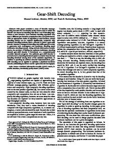
are characterized either in matrix or in graphical representation. Let c denotes the code word and c 5 uG, where, u 5 3 u0, u1, c, uk21 4 , is the information vector to be encoded and G is a k 3 n generator matrix whose rows, 5 g0, g1, c, gk21 6 , span the (n, k) LDPC code. For a generator matrix G (assume it is of full rank), there exists an 1 n 2 k 2 3 k matrix H such that GH T 5 0. Thus for every codeword c [ C, cH T 5 0. Either G or H specifies an LDPC code in matrix form. In graphical representation, an LDPC code is represented by a bipartite graph (also called Tanner graph). Figure 1 shows a Tanner graph, which consists of two classes of nodes, i.e., variable nodes and check nodes, and edges connecting different class of nodes. Variable nodes are associated with bits of the codeword and check nodes are associated with the set of parity-check constraints. The 1-componets in parity-check matrix are associated to edges in Tanner graph. The number of edges connected to a node in a graph is defined as the degree of the node. In matrix representation, it is equal to the number of 1-components in a row (for check node degree) or column (for variable node degree) of the parity check matrix. An LDPC code is called regular if the degree of any check node is a constant and the degree of any variable node is also a constant. Otherwise the code is called irregular. In general, irregular LDPC codes can slightly outperform regular LDPC codes [4], [5]. Structured
1
1
2
2
3
3
4
4
5
Check Nodes
Variable Nodes 6
Figure 1. An example of Tanner graph.
Zhongfeng Wang and Zhiqiang Cui, are with the Senior Member, IEEE, Email:
[email protected].
FIRST QUARTER 2011
IEEE CIRCUITS AND SYSTEMS MAGAZINE
53
Well constructed irregular QC-LDPC codes can consume much less hardware & power consumption compared to computer generated regular random-like LDPC codes with similar size and rate. LDPC codes [6]–[10], which have elegant regularity in the structure of their parity check matrices, are very convenient for VLSI implementation. Typical structured LDPC codes include Quasi-Cyclic (QC) LDPC codes [6]–[8] and shift-LDPC codes [9], [10]. Structured LDPC codes can be constructed as either regular or irregular LDPC codes. These kinds of codes are well-suited for low-power high-speed applications since the regular structures of their H matrices render them easy message passing/routing and memory access in hardware implementation. It is not a surprise that well constructed irregular QC-LDPC codes can consume much less hardware & power consumption compared to computer generated regular random-like LDPC codes with similar size and rate. I.B. Decoding Algorithms for LDPC Codes I.B.1. Belief Propagation Decoding Algorithm The standard belief propagation algorithm (BPA), also known as Sum-Product algorithm (SPA) in the literature, was first proposed by Gallager in [1]. Let C be a binary (N, K) LDPC code specified by a parity-check matrix H with M rows and N columns, where M $ N 2 K. Using a notation similar to [1], let N 1 m 2 5 5 n : Hmm 5 1 6 denote the set of variable nodes that participate in check m. Similarly, let M 1 n 2 5 5 m : Hmm 5 1 6 denote the set of checks in which variable node n participates. Let N 1 m 2 \n represent the set N(m) with variable node n excluded, and M 1 n 2 \m represent the set M(n) with check m excluded. Let c 5 1 c1, c2, c, cN 2 and x 5 1 x1, x2, c, xN 2 denote the coded sequence and the transmitted vector, respectively The received vector and the corresponding harddecision vector are denoted by y 5 1 y1, y2, c, yN 2 and z 5 1 z1, z2, c, zN 2 , respectively. The logarithmic-domain Sum-Product iterative decoding algorithm is formulated as follows. Let Iv 5 In 1 1 Pr 3 cv 5 0|yv 4 2 / 1 Pr 3 cv 5 1|yv 4 2 2 denote the intrinsic message, where Pr 3 cv 5 1|yv 4 (or Pr 3 cv 5 0|yv 4 2 denotes the probability that the transmitted digit in position v is a 1 (or 0) conditional on the received digit in position v. Assume that cv 5 0 and cv 5 1 are equally likely. For binary input, AWGN channel, mapping the transmitted digit as xv 5 1 2 2cv, the intrinsic message can be computed as Iv 5 2yv/s2. Let Rcv represent the check-to-variable message conveyed from the check node c to the variable node v, Lcv 54
IEEE CIRCUITS AND SYSTEMS MAGAZINE
denote the variable-to-check message conveyed from the variable node v to the check node c. The SPA is given as follows: 1) Initialization: Lcv 5 Iv
for v 5 1, 2, c, N and c 5 1, 2, c, M. (1.1)
2) Check-to-variable message passing: Each check node c computes the check-to-variable message Rcv with variable-to-check message Lcv. Rcv 5 q n[N1c2\vsign 1 Lcn 2 3 C 5 g n[N1c2\vC 1 |Lcn| 2 6 , (1.2) eb 1 1 where C 1 b 2 5 lna b b. e 21 3) Variable-to-check message passing: Each variable node v computes the variable-tocheckmessage Lcvwithcheck-to-variablemessage Rcv. Lcv 5 a m[M1v2\c Rmv 1 Iv
(1.3)
4) Tentative decision and parity check: Each variable node v computes the LLR message Lv and makes tentative decision. Lv 5 a m[M1v2 Rmv 1 Iv
(1.4)
zv 5 0
(1.5)
if Lv $ 0, zv 5 1 otherwise.
The decoding is terminated if a valid codeword is found, i.e., zHT 5 0, or the maximum decoding iteration is reached. Otherwise, repeat the steps expressed by Equations from (1.2) to (1.5) for a new decoding iteration. A few variants of SPA were proposed in the literature. A specific reformulation presented in [11] was to balance the computation load of check node processing and variable node processing, which not only reduced the critical path, but also facilitated 100% utilization of hardware. I.B.2. Min-Sum Decoding Algorithms The SPA generally suffers from large computation complexity and is very sensitive to finite word length implementation [11], [12]. An efficient way to reducing its computation complexity is to simplify the computation of check node processing expressed in Equation (1.2) with approximation. Two widely used near-optimum FIRST QUARTER 2011
The original input messages for every variable node and check node can be recovered with a simple algorithmic transformation. LDPC decoding algorithms are scaled Min-Sum algorithm (MSA) and offset Min-Sum algorithm [13], [14]. For the scaled MSA, the check node processing is expressed in Equation (1.6) while Equation (1.7) is used for offset MSA for check node processing. The near-optimum decoding performance can be obtained with a 5 0.75 and b 5 0.15 in most cases. In some cases, we can combine two approximations, e.g., introduce a scaling factor for Equation (1.7). Generally speaking, the performance loss of a well-tuned MSA compared to SPA is less than 0.1 dB. Rcv 5 a 3 Rcv 5
min |Lcn|, q sgn 1 Lcn 2 3 n[N 1c 2\v
n[N1c 2\v
(1.6)
min |Lcn| 2 b, 0b. q sgn 1 Lcn 2 3 maxa n[N 1c 2\v
n[N1c 2\v
(1.7) II. Random-Like LDPC Codes and Decoding The earliest studies on LDPC codes were focused on random codes [1], [3], where the 1-components were randomly (and sparsely) distributed all over the paritycheck matrix with possible constraints on row and/or column degrees. A pioneer design of LDPC decoder for a 1024-b, rate-1/2 random LDPC code was based on a fully parallel architecture [15]. It can be observed that a fully parallel decoding architecture leads to low area utilization ratio and high power consumption in VLSI implementation because of enormous interconnections. In recent years, message broadcasting techniques were introduced to reduce the total amount of interconnecting wires. In [16], the message passing of SPA was rescheduled and a unidirectional message broadcasting technique was proposed. To be more specific, a check node only broadcasts a summation message to its neighboring variable nodes instead of sending out all individual check-to-variable messages to corresponding variable nodes. The needed check-to-variable message for a variable node is recovered using the check node summation message and previously stored variable-to-check messages corresponding to the node. From the hardware implementation point of view, a lot of hard wires are shared for message passing, which reduces interconnect complexity significantly. In [17], the SPA was further reformulated as a bidirectional message broadcasting algorithm. The extrinsic messages computed by every computation node are stored in the node itself and are not sent out. Only summation values are passed among FIRST QUARTER 2011
check nodes and variable nodes. For every computation node, the new extrinsic messages are computed with the received summation value and the previous extrinsic messages stored locally. This decoding scheme brings another tradeoff between interconnect complexity and computation component cost. It can significantly mitigate the routing congestion in a high-speed LDPC decoder implementation. However, because both computation units and memories for soft messages are duplicated, the area and power efficiencies are largely sacrificed. In [18], an efficient message passing decoding scheme using MSA was proposed. In the variable-to-check message passing phase, a variable node v does not send separate variable-to-check messages Lcv to its neighboring check nodes. Instead, the column sum, Lv, is broadcasted to all its neighboring check nodes. In addition, only S old cv (i.e., the sign of Lcv) computed in the previous iteration is sent to the corresponding neighbor check node c . In the check-to-variable message passing phase, a check node c does not send out separate check-to-variable messages to its neighboring variable nodes. Instead, the Rcv messages are sent out in a compressed format, i.e., the smallest magnitude, the second smallest magnitude, the index of the smallest magnitude, and the 1-bit product of all Scv (denoted as min1c, min2c, indexc, and Sc, respectively). The original input messages for every variable node and check node can be recovered with a simple algorithmic transformation. For a variable node v, the sign bits, S old cv , are stored. The needed input Rcv can be recovered as the following, |Rcv| 5 e
min1c, if V 5 indexc min2c otherwise
sign 1 Rcv 2 5 Sc 3 S old cv
(2.1)
where V is the index of the variable node v with regard to its neighboring check node c. In a check node c, the R old cv messages computed in the previous iteration are stored in a compressed format as mentioned before. The needed input Lcv can be recovered with the following equation: old 3 |R old Lcv 5 Lv 2 1 S old cv 3 S c cv | 2
(2.2)
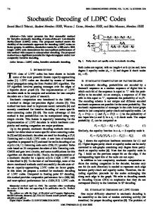
Figure 2(a) illustrates the structure of a variable node with a degree of three. The inputs are compressed IEEE CIRCUITS AND SYSTEMS MAGAZINE
55
4-bit quantization for soft messages. The authors of [18] further extended the efficient message passing scheme to LDPC decoder with a posteriori probability (APP) based MSA [13] for even less implementation complexity at the expense of small performance loss. In the literature, bit-serial arithmetic is also employed to mitigate the routing-congestion in fully parallel LDPC decoders for random-like LDPC codes [19], [20]. In [21]– [23], LDPC decoders with stochastic decoding are presented for low complexity implementation of decoding. More techniques can be found in [24]–[26] about lowcomplexity LDPC decoder design.
Sum –
D
E and S
–
D
E and S
–
D
E and S +
s s s
(a) – – –
Min
– –
s, Min1, Min2, Index
– Distributor
Register
(b) Figure 2. Computation units for reformulated MSA, a) variable node unit, and b) check node unit.
check-to-variable messages from three check nodes. The needed Rcv messages are recovered by equal-andselect (E&S) units expressed with Equation (2.1). In the output side, the sign bit of each Lold cv is sent to the neighboring check node c, where c [ M 1 v 2 . The column sum Lv is broadcasted to all its neighboring check nodes. Figure 2(b) shows the structure of a check node. The inputs are Lv and S old cv from six variable nodes. The needed Lcv messages are recovered using (2.2). The compressed check-to-variable messages are broadcasted to all its neighboring variable nodes. It was reported in [18] that the proposed approach can significantly reduce the amount of outgoing wires per computation unit. Specifically, for an RS-based (6, 32)-regular LDPC code, 54% outgoing wires of each variable node unit (VNU) and 90% outgoing wires of each check node unit (CNU) can be reduced if using
CNU1
m11
m12
m13
m15
CNU3
m31
m32
m33
m35
VNU1
VNU2
VNU3
VNU5
Z1
Z2
Z3
Z5
C1
C2
C3
C5
Figure 3. The structure of a partially parallel decoder for (3, 5) QC-LDPC codes.
56
IEEE CIRCUITS AND SYSTEMS MAGAZINE
III. Structured LDPC Codes and Decoding III.A. Quasi-Cyclic LDPC Codes The most popular class of structured LDPC codes is QC-LDPC code. Many existing works have addressed code construction of QC-LDPC codes [6]–[8], [28]–[30], which can achieve comparable decoding performance to computer generated random codes. Array codes [6] and Euclidian Geometry-based QC-LDPC (EG-LDPC) codes [6] are both interesting sub-classes of QC-LDPC codes. The encoder of a QC-LDPC code can be easily built with shift-registers [31] while random codes usually entail complex encoding circuitry to perform matrix and vector multiplications [32], [33]. Most importantly, QC-LDPC codes facilitate efficient high-speed decoding due to the regularity of their parity check matrices. On the other hand, random-like LDPC codes require complex routing for VLSI implementation, which not only consumes a large amount of chip area, but also significantly increases the computation delay. III.B. Partially Parallel Decoding Architecture for QC-LDPC Codes For decoder design of QC-LDPC codes or structured LDPC codes in general, it is a common practice to use partially parallel decoding architectures [11], [34]–[38], which generally achieve a good trade-off between hardware complexity and decoding throughput. This is because the throughput of a serial LDPC decoder [39] is normally very slow and not suitable for most of modern communication systems while the hardware implementation of a fully parallel architecture [15] is hardwareexpensive and power hungry, or even infeasible due to excessive routing when the block size is moderately large. A typical partially parallel decoder architecture for a (3, 5)-regular QC-LDPC codes is shown in Figure 3, where totally 3 3 5 5 15 memory banks are used to store the soft message symbols exchanged between two decoding phases, memory banks 5 Z1, Z2, c, Z5 6 are used to store the intrinsic information, and memory FIRST QUARTER 2011
banks 5 C1, C2, c, C5 6 are used to store the decoded data bits. For QC-LDPC codes, the address generator for each memory bank can be realized with a simple binary counter, which not only simplifies the hardware design, but also improves the circuit speed. In general, each node processing unit takes one clock cycle (assuming dualport memories are used, otherwise two cycles are needed) to complete message updating for one row (or column) of the parity check matrix. Figure 4 shows a small sub-matrix of a QC-LDPC parity-check matrix, where all 1-components are numbered starting from the first row. With the conventional partially parallel decoding approaches [34], [39], 14 memory entries need to be allocated for the corresponding memory bank. All the soft messages corresponding to those 1-components shown in Figure 4 are stored sequentially in the memory. In the row decoding phase (i.e., the check-to-variable message updating phase), the memory address generator generates 0, 1, . . . ,13. In the column decoding phase (i.e., the variable-to-check message passing phase), the address generator outputs 9, 10, . . . ,13, 0, 1, . . . ,8. Hence, the address generator can be implemented as a simple modulo-13 counter. To increase the parallelism, we can enable each node processing unit to process the data corresponding to 1-components at multiple rows (or columns) of the parity check matrix at the same cycle. However, this will generally cause memory access conflicts since multiple data accesses per cycle are required for each memory bank. Two efficient approaches were proposed in [11]: I) Partition each memory bank into p sub-banks (or called memory segments) where all the soft symbols corresponding to 1-components at p adjacent rows of a sub-matrix are stored in p different segments. II) Store soft messages corresponding to p adjacent rows of a sub-matrix in one memory entry while utilizing extra buffers to solve the memory access conflict. First, let us consider Approach I. Figure 5 shows an example with p 5 4. It can be observed that a straightforward partition scheme shown in Figure 5(a), has memory access conflict in the column decoding phase, where the number (1, 2, 3, or 4) associated with each 1-component in the sub-matrix indicates in which memory subbank the data is stored. It can be noted that the scheme shown in Figure 5(b) can ensure no memory access conflict in either decoding phase. The general rule for the memory partitioning is to greedily store the messages corresponding to the last (partial) group of rows into high indexed memory segments [11]. FIRST QUARTER 2011
0
9
A
B
C
1
2
3
4
5
6
7
8
D
Figure 4. A sub-matrix and its 1-components labeled sequentially.
1
2
3
4
1
2
1 3
4
1
2
3
4
1
2
3
4
2
1
2
3
4
1
2
3
4
1
4
(a)
(b)
Figure 5. Memory partitioning schemes for one memory module. a) a straightforward partition scheme with memory access confliction; b) a contention free memory partitioning scheme.
The second approach is to pack multiple data (e.g., starting from first row) into one memory entry and use simple data switching networks to resolve memory access conflict. Similarly a straightforward packing scheme as shown in Figure 6(a) will lead to memory access conflict in column decoding phase. The new packing scheme proposed in [11] was illustrated in Figure 6 (b) with p 5 4. The switching networks are shown in Figure 7, where Figure 7(a) for row processing, Figure 7(b) for column
1
2
3
3
3
3
4
4 (a)
1
1 1
1
2
2
2
3
3
3
3
4
4
1
1
1
2
2
2
4 (b)
Figure 6. An example of packing multiple data into one memory entry. a) a straightforward packing scheme; b) a better packing scheme.
IEEE CIRCUITS AND SYSTEMS MAGAZINE
57
O4 O4
O4
O3
d4
O3
O2
d3
d4 d4
D2
d3
D1
d2
D3 D2
d2
D1
O1 d1
D3
O3
d3
D2
O2
d2
D1
O1
O2 O1
d1
d1 En (a)
En (b)
En (c)
Figure 7. The switching networks for a) row processing phase, b) column decoding phase, and c) for both decoding phases.
⎡ H11 ⎢H 21 H= ⎢ ⎢L ⎢ ⎣ Hc1
H12
L
H22
L
L
O
Hc2
L
H1t ⎤
1 1
⎥ 1 ⎥ 1 ⎥ L 1 1 ⎥ Hct ⎦ 1
H2t
1 1
1
1 1
1 1 1
1 1 1
Table 1. Decoding schedule designed for shift decoder architecture.
1 1
1 1
1 1
Figure 8. The parity-check matrix structure of shift-LDPC codes.
processing and Figure 7(c) for combined row/column processing, where “En” stands for an enable signal. In addition, signals d1, d2, d3, and d4 represent the loaded data from a memory bank at the current cycle, O1, O2, O3, and O4 denote the output data to be sent to the corresponding row or column processing units. It can be seen that, with the modified data packing scheme, multiple times speed-up in LDPC decoding over the traditional partially parallel decoding architecture can be achieved. It is worth noting that either kind of enhanced partially parallel decoder architecture requires no extra memory storage. Hardware overhead is only introduced in node processing units. By exploring special properties of MSA, the above discussed partly parallel decoder architecture was later extended to memory-efficient parallel decoder architectures [27], which can save significant amount of memory for extrinsic messages, particularly for high-rate LDPC codes. III.C. Shift-LDPC Codes and Shift-Structured Decoder Architecture III.C.1. Shift-LDPC Code Shift-LDPC code was first presented by Sha et al in 2006 [10]. It is a class of implementation-oriented LDPC codes which have comparable decoding performance to compute generated random codes. A regular 1 N, M 2 58
IEEE CIRCUITS AND SYSTEMS MAGAZINE
Min-Sum Algonthm and Decoding Schedule 1: Initialization: Lvc 5 IV, i 5 0, 1, . . . ,N21; 2: repeat 3: for k 5 0 to k 5 dc 21 do 4: {process of kqth ~ (k 1 1)qth columns} 4: compute Rcv from row process result of last iteration 5: magnitude of Rcv 5 minimum or 2nd–minimum 6: sign of Rcv 5 q 1 2 sign(Lnc) 3 sign(Lvc) n[N c 7: for q columns process: 8: Lvc 5 a R 1 Iv 2 Rcv m[M 1v 2 mv 9: for all check nodes (receive one Lvc per row): 10: update minimum 2nd–minimum, location of minimum; 11: record signs 12: end for 13: until max iteration times reached or convergence to a code word 14: Output: decoded bit 1 c, t 2 -regular shift LDPC code is shown in Figure 8, with N 5 t 3 q and M 5 c 3 q, where each submatrix has a dimension of q 3 q. As displayed, the parity check matrix consists of c 3 t sub matrices. The structure of each submatrix Hi1 1 1 # i # c 2 in the leftmost block column H1 is an arbitrary column permutation of the identity matrix. The block column Hj is decided by the block column Hj21 1 2 # j # t 2 . More specifically, the 1’s of the block column Hj are cyclic-shifted up by 1 space of the block column Hj21. By using girth optimization, the performance of shift-LDPC codes can be comparable to computer generated random codes or QC-LDPC codes adopted in multiple IEEE standards [9]. III.C.2. Shift-Structured Decoder Architecture In [9], [10] Sha et al proposed a specific high-speed decoder architecture targeting for multi-Gbps applications, FIRST QUARTER 2011
Either kind of enhanced partially parallel decoder architecture requires no extra memory storage.
namely shift decoder architecture. It was dedicated for the class of shift-LDPC codes. In contrast with conventional decoder architectures, the shift-structured decoder architecture has three major merits: high parallel level of decoding, efficient message memory usage, and low routing complexity. Its decoding schedule, overall architecture and node processor design is briefly discussed in the following. Firstly, by combining the decoding schedule and MSA, the decoding process can be expressed as follows: The whole check node process is divided into t steps and q columns are processed concurrently in one clock cycle. In each clock cycle, q VNUs get M check-to-variable messages and compute the M variable-to-check messages, so that M CNUs get one message each, so each CNU can deal with one step of the check node process. With this decoding schedule, one iteration can be finished in t clock cycles.
With conventional LDPC decoding, check nodes only communicate with variable nodes. In shift-LDPC decoder architecture, some regular communications between check nodes are intentionally introduced to adapt the shift property in matrix construction. By introducing these originally unwanted communications, the complexity of connections between CNUs and VNUs can be significantly reduced. It can be ensured that each CNU only connects to a fixed VNU. Thus the communication between CNUs and VNUs required by the original LDPC decoding algorithm is decomposed into three kinds of connections: 1) the simplified connection between CNUs and VNUs; 2) the CNU communication network (intra iteration), and 3) the CNU communication network (inter iterations). CNU communication network (intra iteration) and CNU communication network (inter iterations) transfer the row processing results during iteration and between iteration respectively. Figure 9
CNU Communication Network (Inter Iteration)
Iteration Start CNU1 CNU2 CNU3 CNU4
CNU1
CNU3
CNU2
CNU4
CNU3
CNU1
CNU4
CNU2
VNU 1 2 3 4
VNU 1 2 3 4
VNU 1 2 3 4
1
CNU2 CNU3 CNU4 CNU1
1 1 1 Clock Cycle 1
CNU1
1 1 1 1 Clock Cycle 2
CNU2
CNU3
CNU3 CNU4 CNU1 CNU2
1 1 1
1 Iteration Finish
Clock Cycle 3
CNU4
CNU Communication Network (Intra Iteration) Figure 9. Communication relationships of the shift-LDPC code decoder.
FIRST QUARTER 2011
IEEE CIRCUITS AND SYSTEMS MAGAZINE
59
shows an example of the communication relationships in a simple shift decoder. Because only one variable-to-check message is processed or generated in one time, the CNU has very low complexity as illustrated in Figure 10. Only row process results instead of the messages are stored and they are stored in a compressed way. Only the minimum magnitude, 2nd-minimum magnitude, the location of the minimum and the sign bits are stored. On the other side, the architecture of variable node processing unit is designed with only combinational logic. To increase the clock frequency, some levels of pipeline stages can be added to the data path, though the number of clock cycles will be slightly increased for each iteration. It was shown in [9] that, by applying 2-level pipelining, the clock frequency can be doubled. The design example used was a (8192, 7168) (4, 32)-regular shift LDPC code. It occupies a die size of 4.1 mm 3 4.1 mm under 0.18 mm CMOS process with six metal layers. The logic density is 70% and no routing congestions is
encountered. The throughput achieved is 5.1 Gbps at a maximum iteration of 15. Compared with partially parallel LDPC decoder architectures, the shift-structured decoder can achieve considerable improvement in hardware efficiency. It is very efficient for high-speed LDPC decoder implementation. III.C.3. Other Applications of Shift Decoder Architecture The above discussed shift-structured LDPC decoder architecture, or simply shift decoder architecture, can be applied to some other classes of LDPC codes, e.g., QC-LDPC codes and RS-based LDPC codes. Figure 11 illustrates a simple way to transform the parity check matrix of a QC-LDPC code into a shift kind matrix whose decoder can be implemented with the shift decoder architecture. Firstly the q columns are distributed to t block columns of Hqcs1 in a round-robin fashion. Then the second q columns are permuted in the same way and so on until all columns are distributed into new
Iteration Start To Old Register of the Succeeding CNU
Old Register
From Old Register of the Prior CNU
1 Index
From New Register of Last Iteration
>>
0
Min and Second – Min
>
Data Select Message to VNU
Sign Sign Bit Popped from Sign Register Sign Register
Sign
Message Computation
Min and Second – Min
Index From New Register of the Prior CNU
Magnitude
Compare
Min and Second – Min Sign
Index Index Set
Message from VNU
Index
New Register
Sign
Sign
Magnitude Comparison
To New Register of the Succeeding CNU
Figure 10. Architecture of check node processing unit.
60
IEEE CIRCUITS AND SYSTEMS MAGAZINE
FIRST QUARTER 2011
matrix Hqcs1. In [43], Cui et al proposed an efficient matrix permutation method to minimize the maximum row weight of each transformed sub-matrix. Similarly the matrix permutation for QC-LDPC codes can be performed row-wise to facilitate row-wise shift decoding. Interested readers are referred to [41] for more information. In addition, the shift decoder architecture can be applied to RS-based LDPC codes [82], which are a special class of LDPC codes based on Reed-Solomon codes. This code ensemble is well known for its excellent error-correcting performance and has been selected as the forward error correction coding scheme for 10GBaseT systems. By exploiting the algebraic generation process of parity check matrix, it was found that the shift property is hidden in the RS-based LDPC code matrix [47]. A high-speed decoder for a (2048, 1723) regular RS-LDPC code was designed therein, which achieved 10 Gbps throughput with 820 K gates. More details can be found in [47].
check node message passing phase, every check node obtains all variable-to-check messages specified by the Tanner graph and computes all check-to-variable messages. In the variable node passing phase, every variable node gets all check-to-variable messages specified by the Tanner graph and calculates all variable-to-check messages. Recently it has been found that more precise and/or flexible message scheduling is able to significantly speed up the decoding convergence. For VLSI implementation, layered message passing has attracted extensive attention for its fast convergence speed and implementation regularity; and it is widely utilized in recent LDPC decoder designs. Row-layered message passing has been investigated in turbo-decoding message-passing (TDMP) [65], [76], serial message-passing [59], layered decoding [60], optimized message passing schedules [61], approximate layered decoding [43], and extended layered decoding [79] to improve decoding throughput. Column-layered message passing has been discussed in shuffled iterative decoding [62], [78] and MSA based column-layered decoder design [41]. With a layered message passing, the message updating is
IV. Layered Decoding The original LDPC decoding algorithm invented by Gallager [1] is a two phase decoding approach. In the
1
Hqc =
A B C D E F G H A2 B2 C2 D2 E2 F2 G2 H2
2 1
3
4
5
6
7
8
1′
2′
3′
4′
5′
6′
7′
1
1′′ 2′′ 3′′ 4′′ 5′′ 6′′ 7′′ 8′′ 1 1
1 1
1
1 1
1
1 1
1
1
1
1
1
1
1
1
1
1
1 1
1
1
1
1
1
1
1
1
1
1
1
1
1 1
1
1
1
1 1
1
1
8′
1
4
1 1
7
3′ 6′ b
2′′ 5′′ 8′′
2
5
8
1
1′ 4′ 7′ 3′′ 6′′ b
3
6
b
2′
5′ 8′ 1′′ 4′′ 7′′
1
1
1
1
1
1
1
1
1
1 1
1
1
1
1 1
Hqcs1 =
1
1
1
1
1
1
1
1 1
1
1
1
1 1
1
1 1
1
1
1
1 1
1
1
1 1
1
1
1
1
1
1
Figure 11. The transformation from the example QC-LDPC parity check matrix into a shift like LDPC code through column permutation.
FIRST QUARTER 2011
IEEE CIRCUITS AND SYSTEMS MAGAZINE
61
In hardware implementation, it is preferable to adopt MSA in layered decoding for less implementation complexity. performed layer by layer. Each previous layer passes extrinsic information to the next layer. In one decoding iteration, messages between rows and columns are exchanged multiple times, which speeds up the decoding convergence. More flexible message scheduling is introduced in residual belief propagation [81] and approximate residual belief propagation [80] to further increase the decoding convergence speed. However, the VLSI implementation of residual belief propagation is under-investigated. IV.A. Row Layered Decoding and Architecture The row-layered decoding is the most popular layered message passing scheme which performs LDPC decoding block row by block row. In the literature, several practical designs have adopted this technique [63]–[66]. In the row-layered decoding approach, the parity check matrix of LDPC code is partitioned into L row layers: H 5 3 HT0 HT2 c HTL21 4 . Each layer defines a supercodes Cl and the original LDPC code is the intersection of all supercodes: C 5 C0 d C2 c d CL21. In one decoding iteration, the message updating is serially performed from row layer l 2 1 to row layer l. Figure 12 il-
C0 1 1 1 C1 1 1 1 C2 1 1 1 C3 1 1 1 C4 1 1 1 C5 1 C6 1 C7 1 C8 1 C9 1
1
L0v
1
L1v
1 1 1 1 1
1
L4v
L9v
1 1
1
1 1
1
L8v
1
(a) 1 C0 1
1
1
1
1
1
1
1
1
1
1
1 1
1
1
1
1
1
1
1
1 1
C1
1 1
1
1 1
L1v
1 1
1
L0v
1 1
1
1
(b) Figure 12. The row-layered partitioning of parity check matrix. a) single row partitioning; b) block row partitioning.
62
IEEE CIRCUITS AND SYSTEMS MAGAZINE
lustrates two different row-layered partitioning of parity check matrix. In Figure 12(a), the original LDPC code is viewed as the intersection of ten supercodes. Each row layer only contains one row of H matrix. The maximum variable node degree of every supercode is at most one. In Figure 12(b), the original LDPC code is viewed as the intersection of two supercodes. A row layer contains multiple rows of H matrix. The maximum variable node degree of every supercode is more than one. For a variable node v, the variable-to-check message for a check node c in layer l is obtained by subtracting the old check-to-variable message from the LLR messages computed from layer l 2 1. Let’s label the LLR message from layer 1 l 2 1 2 to l for variable node v as Lv1l212. The decoding algorithm for a layer l is formulated in Equation (4.1)–(4.3). 1l212 l l Lnew, 5 Lnew, 2 Rold, cv v cv new,l Rcv 5
q
n[N1c 2\v
2 3Ce sign 1 Lnew,l cn
1l212 5 Lnew, 2 Lnew,l v v
old,l a Rmv 1
m[M l 1v2
(4.1) new,l a C 1 Lcn 2f
(4.2)
new,l a Rmv ,
(4.3)
n[N1c 2\v m[M l 1v2
where, M l 1 v 2 denotes the set of check nodes in the lth layer connected to the variable node v. C 1 x 2 5 2log 3 tan h 1 |x|/2 24 is a nonlinear function. In the initialization of decoding, all old check-to-variable messages (i.e., Rold cv : c 5 1, 2, c, M and v 5 1, 2, c, N 2 , are set to zero. The intrinsic messages are assigned to 1l212 for v 5 1, 2, c, N. In hardware implementation, Lnew, v it is preferable to adopt MSA in layered decoding for less implementation complexity. The decoding performance and the convergence speed of row-layered decoding are discussed in [59], [77]. A simplified layered decoder architecture is shown in Figure 13. The MSA algorithm is assumed for low computation complexity. Each CNU performs the Equation (4.2) for a check node. Each VNU performs Equation (4.3) for a variable node. For clarity, it is assumed that, for every layer, the variable node degree is one. It contains one adder and one subtractor. For QC-LDPC codes, the shuffle network is implemented with an array of cyclic shifters to align the order of variable-to-check messages to the row order of the current layer. For wireless applications, the highest throughput requirement is usually a few hundred Mbps. A folded FIRST QUARTER 2011
For high-speed wireline communication, it is essential to utilize the maximum decoding parallelism for very high decoding throughput. all extrinsic messages corresponding to a complete row layer can be updated in one clock cycle. However, it causes very long critical path and significantly slows down the clock frequency. This problem can be significantly mitigated by using a relaxed pipelining technique while slightly sacrificing decoding performance. The algorithmic and architectural details can be found in [43]. It is estimated that more than 4.7 Gbps decoding throughput can be achieved at 15 iterations with 250 MHz clock frequency using 0.13u CMOS technology. IV.B. Column Layered Decoding and Architecture An alternative layered decoding scheme is called column layer decoding. Similar to row-layered message passing, the extrinsic messages are passed block column by block column in column-layered decoding. The maximum number of decoding iterations can be significantly reduced for the same decoding performance. The original idea was presented as a shuffled decoding scheme [62], which is essentially an SPA-based columnlayered decoding algorithm and involves huge amount of redundant computation. By incorporating MSA and utilizing algorithmic approximation, the MSA-based column-layered decoding presented by Cui et al [41] is
CNU
Decompressor Check-to-Variable Message Memory
+ LLR Message
+
+ –
VNU
Decompressor
VNU
CNU
Decompressor
Shuffle Network
implementation structure is feasible to meet the data rate requirement and can save implementation cost. In [66], the implementation of a QC-LDPC decoder for IEEE 802.11n is described. The decoder updates the extrinsic message for one cyclic matrix in a clock cycle. Offset MSA and row layered message passing are employed. The memories for check-to-variable and variable-to-check messages operate at twice the clock frequency of the primary sequential logic to satisfy the memory access bandwidth. The maximum information decoding throughput is 780 Mbps at five decoding iterations with 208 MHz clock frequency and 0.18um ASIC technology. In [64], a reconfigurable LDPC decoder for the IEEE 802.11n and 802.16e is presented. In each clock cycle, the extrinsic messages corresponding to two sub-matrices in the same layer are processed. The extrinsic messages are processed row-layer by rowlayer. The layered decoding is based on belief propagation algorithm. A maximum throughput of 1 Gbps at ten iterations is achieved with 450 MHz clock frequency and 90 nm CMOS technology. For high-speed wireline communication, it is essential to utilize the maximum decoding parallelism for very high decoding throughput. With row-layered decoding,
–
+
Variable-to-Check Message Memory
Variable-to-check Messages
Intrinsic Messages
Figure 13. A simplified decoder architecture employing row-layered decoding.
FIRST QUARTER 2011
IEEE CIRCUITS AND SYSTEMS MAGAZINE
63
comparable to row layered decoding in terms of computation complexity and convergence speed, but it has some advantages in high-speed decoder implementation of high-rate LDPC codes. Figure 14 illustrates two different column-layered partitioning schemes of a parity check matrix. In Figure 14(a), the parity check matrix is partitioned such that each column layer only contains one column of H matrix. The maximum check node degree of each layer is at most one. In Figure 14(b), the H matrix is partitioned into three layers. A column layer contains multiple columns of H matrix. The maximum check node degree is more than one for some layers. In one decoding iteration, the message updating is serially performed from column layer g 2 1 to column layer g. For a check node c, the check-to-variable message for a variable node v in layer g is obtained with all latest variable-to-check messages associated to the check node. Assume that the message updating is performed in the order of variable node index, the computations for a layer g is formulated in Equations (4.4)–(4.6). Each variable node v computes the LLR message Lv as expressed by Equation (4.6), and makes tentative decision. new old Rnew cv 5 q n[N 1c 2\v,n,vsign 1 Lcv 2 3 q n[N 1c 2\v,n.vsign 1Lcn 2
3C ca
C 1|Lnew cv |2 1 a
n[N 1c 2\v,n,v
C 1|Lold cv |2d
n[N 1c 2\v,n.v
(4.4)
1
1 1
1 1
1
4
9
Rc
14
1
1
1
1
1
1 1
1
1
1
1
1 1
1 1 1
1 1 1
13
Rc
1 1
1 1
1
(4.6)
1 1
1
1 1
Rc
1
1 1
1
1
Rnew mv 1 Iv
G2
1
(4.5)
G1
1 1
0
G0 1
1
1
1 1
1
1
Rc Rc
G14
1
G13
G12
G11
1
1
m[M 1v2
1 Iv
In a check node c, the computation in Equation (4.4) is repeatedly performed for every layer, it requires extensive computation complexity. The MSA-based columnlayered decoding mainly simplifies the magnitude computation in Equation (4.4) by introducing a two-step updating for the sorted sequence mc1g2, which contains the magnitudes of variable-to-check messages associated to the check node. Step-a: remove the |Lold cv | from the sorted sequence 1g212 old if the |Lcv | is in the sequence. The magnitude of mc the check-to-variable message is the smallest magni| 1g212. tude retaining the new sequence m c new Step-b: after the Lcv is generated, sort the magnitude of the new variable-to-check message |Lnew cv | and | 1g212 to obtain m1g2 for layer g. m c c The generic column-layered decoder architecture is illustrated in Figure 15. It is assumed that all extrinsic messages corresponding to a column layer are computed in one clock cycle. The CNUa components perform | 1g212 and the computation of Step-a. They generate m c new Rcv . Then all check-to-variable messages corresponding to the layer g are sent to the appropriate VNU components through the shuffle networks. As shown in Figure 15, the variable-to-check messages are sent to the CNUb components through a reverse shuffle network. The
1 1
1
Rnew m[M 1v2\c mv
Lnew 5a v
1 1
1
1
G10
1 1
1
G9
1
G8
1 1
G7
G6
G5
G4
G3
G2
G1
G0
1
Lnew cv 5 a
1
0
1
Rc
Rc
1 1 1
R
2
Rc
Rc
(a)
(b)
Figure 14. The column-layered partitioning schemes of parity check matrix. a) single column partitioning; b) block column partitioning.
64
IEEE CIRCUITS AND SYSTEMS MAGAZINE
FIRST QUARTER 2011
To speed up the decoding throughput, the messages associated to multiple sub-blocks in a column layer can be processed in one clock cycle.
CNUb component associated to check node c computes the sorted sequence mc1g2 for layer g. It was shown in [41] that a column layered decoding architecture has advantages over row layered decoding for high speed VLSI implementation. For example, the variable-to-check messages in column-layered decoding are used on-the-fly. Thus significant amount of memory access activities and corresponding power consumption are reduced. To speed up the decoding throughput, the messages associated to multiple subblocks in a layer can be processed in one clock cycle. For row-layered decoding, it increases the complexity of each CNU and requires the serial concatenation of multiple comparison and selection stages for VLSI implementation. Significant hardware overhead is required to enable the corresponding circuitry for very high clock frequency [64]. In column layered decoding, the major implementation complexity is associated with VNUs. Because only addition operations are performed in a VNU, it is very convenient to employ arithmetic optimization to minimize the critical path. In general, over 5 Gbps decoding throughput can be achieved at moderate complexity with column-layered decoding.
V. Non-Binary LDPC Code Decoding Non-binary LDPC codes, which are extension of binary LDPC codes, were first presented by Davey and MacKay in 1998 [44]. The non-zero entries in the parity check matrix of a non-binary LDPC code are directly replaced by elements in a Galois field. The performance of non-binary LDPC codes has been shown to be better than binary LDPC codes under binary Gaussian channel in previous works [44], [45]. In [44], an improvement of 0.3 dB is achieved by moving an irregular 1/3 rate code from binary to GF(8) construction. When the multiple-input multiple-output (MIMO) channel is considered, it is shown in [46] that nonbinary LDPC codes over a small Galois field (up to GF(16)) outperforms certain binary LDPC codes while employing joint (MIMO) detection and (channel) decoding. At BER 5 10 –4, using 16QAM modulation, it is also shown in [48] that a separate detection and decoding MIMO system employing a non-binary LDPC code over GF(256) outperforms the joint detection and decoding system employing an optimized irregular binary LDPC code [49] by 0.37 dB.
CNUb CNUb
CNUb
CNUa
Shuffle Network
CNUa
Shuffle Network
VNUs
CNUa
Shuffle Network
CNUa
CNUa
Shuffle Network
Check-to-Variable Message Memory
CNUa
Check-to-Variable Message Memory
Intrinsic Message Memory
CNUb CNUb
CNUb
Figure 15. The generic architecture of column-layered decoding.
FIRST QUARTER 2011
IEEE CIRCUITS AND SYSTEMS MAGAZINE
65
It is highly desirable that a design could adapt to different coding rates to meet various service requirements and channel conditions. A considerable amount of research effort has already been spent on studying efficient decoding algorithms for non-binary LDPC codes in the past. In [44], an extended SPA, which was originally designed for binary LDPC codes, was proposed for decoding non-binary LDPC codes. The computational complexity of the SPA is dominated by O 1 q2 2 sum and product operations for each check node processing, where q is the cardinality of the Galois field. The SPA can also be implemented in the probability domain using m-dimension two-point fast Fourier transforms (FFT) if the finite field is of characteristic two and order m [45]. In this case, the complexity will be dominated by O 1 q log2 q 2 sum and product operations for each check node processing. Although this improvement helps, the FFT based SPA (FFT-SPA) still needs a considerable amount of multiplication operations. In [50], exponential and logarithm operations, which can be implemented with look-up tables (LUT), are introduced into the FFT-SPA to remove hardware expensive multiplications during the check node and variable node processing. For VLSI implementation of non-binary LDPC decoding algorithms, this approach is quite effective when the cardinality of the Galois field is small. However, it suffers from serious hardware overhead when q is large because the size of LUT will be exponentially increased. Similar to the MSA for binary LDPC codes, the SPA for non-binary LDPC codes can also be approximated in the logarithmic domain. In [51] the log-SPA and max-log-SPA were presented. For the original log-SPA, a Jacobi logarithm is used to compute the max*(x, y) function. In order to simplify this computation, the max*(x, y) function can be replaced by the simple max(x, y) function which returns the larger value between x and y. The computational complexity of max-log-SPA, which is a simplified log-SPA, is dominated by O 1 q2 2 sum and comparison operations. Based on max-log-SPA, an extended minsum (EMS) algorithm, which reduces message memory requirement, was proposed in [52]. In [53], the authors proposed a Min-Max decoding algorithm together with a selecting algorithm to reduce the number of comparisons in check node processing. Though much effort has been spent in the design of efficient decoding algorithms and code constructions, little has been done in the decoder architecture design for non-binary LDPC codes due to the inherent large complexity of non-binary LDPC decoding algorithms 66
IEEE CIRCUITS AND SYSTEMS MAGAZINE
as well as a lack of hardware-friendly high performance codes. An FPGA implementation based on the decoding algorithm using FFT in the log-domain was proposed in [54] with large complexity. In [55] a kind of VLSI decoder architecture was proposed based on EMS decoding. None of these works shows comparable implementation complexity for a non-binary LDPC decoder to its binary counterpart. The check node processing is the most complex part in a non-binary LDPC decoding algorithm. Many efforts have been spent on the simplification of check node processing [53]–[55]. In [53], a simple approach was proposed to reduce this complexity by reducing the number of symbols involved in the Min-Max decoding algorithm. The most complex computation in this selective implementation is to find the q 1 1 smallest ones among 2q values. A good sorting method has the complexity of O 1 q log2 q 2 . In order to avoid the sorting process, the authors in [53] proposed a method which divides the 2q values into some small subsets. However, this algorithm transformation introduces lots of normalization operations which are computation intensive. In [56], Lin et al developed a simplified selecting algorithm to make the algorithm more hardware friendly. In [57], a kind of partially parallel decoder architecture is further developed for non-binary QC LDPC codes to achieve better trade-off between hardware complexity and data throughput. The multiplications in check node processing are eliminated by algorithm transformation. Then partially parallel architectures for check node and variable node processing units are applied and improved. The ASIC implementation for a (620, 310) non-binary QC-LDPC code decoder over GF(32) was reported to achieve 60 Mbps throughput under 200 MHz clock speed with 14.9M gate count. In spite of many existing works, there still needs a lot of research efforts to further reduce the complexity of non-binary LDPC decoders to enable them to be competitive solutions in practical communication and/or data storage systems. VI. Multi-Rate LDPC Codes and Decoding In practice, especially for wireless applications, it is highly desirable that a design could adapt to different coding rates to meet various service requirements and channel conditions. To this end, recently more and more LDPC decoders have been developed to support the flexibility in both code rate and code length. It has been FIRST QUARTER 2011
demonstrated that QC-LDPC codes with different code rates and code lengths can be easily designed under the same base structure [64], [67], [68]. Sun et al designed one decoder for high throughput, variable block-size and multi-rate QC-LDPC codes in [64], where barrel shifters were used for cyclically shifting the node messages to the correct PEs, and the reverse operation was eliminated by exploring the properties of QC-LDPC codes. Masera et al in [67] proposed an implementation of a flexible LDPC decoder which could be tailored to decode both IEEE 802.11n and IEEE 802.16e LDPC codes. The decoder implemented a lowtraffic BP algorithm, which achieved a remarkable interconnect reduction between nodes. The Benes networks [69] were used to establish non-blocking connections among processing elements. Zhang et al in [68] presented a decoder architecture for multi-rate QC-LDPC codes in broadband TV broadcasting systems (i.e., China’s DTTB). In this design, a novel check node processing unit is presented to reduce the complexity and facilitate the multiplexing of the processing units. For Mobile WiMAX systems, several reconfigurable hardware designs have been proposed in recent years [58], [70], [71]. Kuo and Willson in [70] implemented a flexible and power-efficient decoder architecture employing a layered-decoding algorithm and a low-complexity offset-MSA for Mobile WiMAX standards. In order to operate in 19 kinds of modes specified in Mobile WiMAX system, including block sizes of 576, 672, . . . , 2304 four design techniques are proposed in [58]: reordering of the base matrix, overlapping operations of main computational units, early termination strategy and multi-mode design strategy. In [71], the computation in a check-function unit (CFU) is performed sequentially; therefore, the CFUs can operate with different code structures of irregular check degrees. Also decoding structures for CMMB and DVB-S2 have been addressed in [72] and [73], respectively. To support the two code rates of the CMMB standard, VNUs and CNUs are dynamically reconfigurable in [72]. Specifically, the two decoding modes have different memory access patterns. The paper [73] proposes an efficient partitioning by any factor of M-kernel parallel hardware structure without memory addressing overhead and keeping unchanged the efficient message mapping scheme. Lee and Ryu in [74] presented a flexible LDPC decoding architecture to support multiple code rates and code lengths with very high decoding throughput. The proposed architecture also employs Benes network to implement configurable interconnection network. Zhang et al [75] presented a multi-Gbps reconfigurable decoder architecture for shifter-LDPC codes. This design shows very high hardware efficiency and is suitable for ultra high speed applications. FIRST QUARTER 2011
VII. Conclusions In this work, we have reviewed popular two phase message passing decoding algorithms for LDPC codes. We have discussed random-like and structured LDPC codes and corresponding VLSI decoding architectures. Specifically we have introduced shift-LDPC codes and shiftstructured decoder architectures for high-speed LDPC decoding. We have also addressed the research on nonbinary LDPC codes and multi-rate LDPC codes decoding architectures. Zhongfeng Wang (M’00, SM’05) received B.E. and M.S. degrees, both from the Department of Automation at Tsinghua University, Beijing, China. He obtained the Ph.D. degree from the Department of Electrical and Computer Engineering at the University of Minnesota, Minneapolis in 2000. In the past, he has worked for Beijing Hua-hai New Technology Development Co., Beijing, CHINA, Morphics Technology Inc. (now a part of Infineon Technology), Campbell, CA, USA, National Semiconductor Co., Longmont, CO. From 2003 to 2007, he worked as Assistant Professor in the School of EECS at Oregon State University (OSU), Corvallis, OR. Since June 2007, he has been working for Broadcom Corporation, Irvine, CA, as Senior Principle Scientist. Dr. Wang was the recipient of the IEEE Circuits and Systems (CAS) Society VLSI Transactions Best Paper Award in 2007 and the recipient of the Best Student Paper Award (1st prize) at the IEEE Workshop on Signal Processing Systems in 1999. He has edited one book “VLSI” (InTech Publisher), authored/coauthored over 100 technical papers, and filed numerous U.S. patent applications. He served as Associate Editor (AE) for the IEEE Trans. on Circuits and Systems: I (TCAS-I) from 2003 to 2005. He is serving as AE for TCAS-II (2008–2011) and AE for IEEE Transactions on VLSI Systems 2009–2012. He has also served as technical program committee member for many IEEE and ACM conferences. He is currently in the technical committee of VLSI Systems and Applications (VTA-TC) and Circuits and Systems for Communications (CAS-COM) in the IEEE CAS Society. His current research interest includes VLSI design for very high speed networking. Zhiqiang Cui received the B.E. degree from the University of Electronic Science and Technology of China in 1993. He obtained the M.E. degree from Texas A&M University, College Station, Texas in 2003 and the Ph.D. degree from Oregon State University, Corvallis, Oregon IEEE CIRCUITS AND SYSTEMS MAGAZINE
67
in 2007. He has been working at Qualcomm Incorporated, San Diego, CA since 2007. Dr. Cui has published four technical papers in IEEE and IET journals and many technical papers in IEEE, ACM, and NASA conferences. He has served as a technical program committee member for a few international conferences and reviewer for numerous international journals and conferences. He is an IEEE senior member. His research interests include VLSI design for communications. Jin Sha received the B.S. degree in physics in 2002, and received the Ph.D. degree in microelectronics in 2007, both at the Nanjing University, Nanjing, China. From 2007 to 2008, he worked for the OmniVision Technologies, Inc as an ASIC design engineer. Since 2008, he has been worked for the School of EE at Nanjing University, China as an assistant professor. His research is focused on VLSI architectures and integrated circuit (IC) design for communications, coding theory applications, and image signal processing.
References [1] R. G. Gallager, “Low-density parity-check codes,” IRE Trans. Inform. Theory, vol. IT-8, pp. 21–28, Jan. 1962. [2] D. J. Costello, A. E. Pusane, S. Batesy, and K. S. Zigangirov. A comparison between LDPC block and convolutional codes [Online]. Available: http://ita.ucsd.edu/workshop/06/papers/253.pdf [3] D. J. C. MacKay, “Good error-correcting codes based on very sparse matrices,” IEEE Trans. Inform. Theory, vol. 45, pp. 399–431, Mar. 1999. [4] M. Luby, M. Mitzenmacher, A. Shokrollahi, and D. Spielman, “Analysis of low-density codes and improved designs using irregular graphs,” in Proc. 30th ACM STOC, 1998, pp. 249–258. [5] X.-Y. Hu, E. Eleftheriou, and D. M. Arnold, “Regular and irregular progressive edge-growth tanner graphs,” IEEE Trans. Inform. Theory, vol. 51, no. 1, pp. 386–398, Jan. 2005. [6] J. L. Fan, “Array codes as low-density parity-check codes,” in Proc. 2nd Int. Symp. Turbo Codes, Brest, France, Sept. 2000, pp. 545–546. [7] Kou, J. Xu, H. Tang, S. Lin, and K. Abdel-Ghaffar, “On circulant low density parity check codes,” in Proc. 2002 IEEE Int. Symp. Information Theory, 2002. [8] Z. Li and B. V. K. V. Kumar, “A class of good quasi-cyclic low-density parity check codes based on progressive edge growth graph,” in Proc. 38th Asilomar Conf. Signals, Systems and Computers, 2004, vol. 2, pp. 1990–1994. [9] J. Sha, Z. Wang, M. Gao, and L. Li, “Multi-Gb/s LDPC code design and implementation,” IEEE Trans. VLSI Syst., vol. 17, no. 2, pp. 262–268, Feb. 2009. [10] J. Sha, M. Gao, Z. Zhang, L. Li, and Z. Wang, “Efficient decoder implementation for QC-LDPC codes,” in Proc. IEEE Int. Conf. Communications, Circuits and Systems (ICCCAS), June 2006, vol. 4, pp. 2498–2502. [11] Z. Wang and Z. Cui, “Low complexity, high speed decoder design for quasi-cyclic LDPC codes,” IEEE Trans. VLSI Syst., vol. 15, no. 1, pp. 104–114, Jan. 2007. [12] T. Zhang, Z. Wang, and K. K. Parhi, “On finite precision implementation of low density parity check codes decoder,” in Proc. 2001 IEEE Int. Symp. Circuits and Systems, May 2001, vol. 4, pp. 202–205. [13] J. Chen and M. Fossorier, “Near optimum universal belief propagation based decoding of low-density parity check codes,” IEEE Trans. Commun., vol. 50, pp. 406–414, Mar. 2002.
68
IEEE CIRCUITS AND SYSTEMS MAGAZINE
[14] J. Chen, A. Dholakia, E. Eleftheriou, M. P. C. Fossorier, and X.-Y. Hu, “Reduced-complexity decoding of LDPC codes,” IEEE Trans. Commun., vol. 53, pp. 1288–1299, Aug. 2005. [15] A. J. Blanksby and C. J. Howland, “A 690-mW 1-Gb/s 1024-b, rate-1/2 low-density parity check code decoder,” IEEE J. Solid-State Circuits, vol. 37, pp. 404–412, Mar. 2002. [16] A. Darabiha, A. C. Carusone, and F. R. Kschischang, “Multi-Gbit/sec low density parity check decoders with reduced interconnect complexity,” in Proc. IEEE Int. Symp. Circuits and Systems, May 2005, vol. 5, pp. 5194–5197. [17] S.-H. Kang and I.-C. Park, “Loosely coupled memory-based decoding architecture for low density parity check codes,” IEEE Trans. Circuits Syst. I, vol. 53, pp. 1045–1056, May 2006. [18] Z. Cui and Z. Wang, “Efficient message passing architecture for high throughput LDPC decoder,” in Proc. 2007 IEEE Int. Symp. Circuits and Systems, May 2007, pp. 917–920. [19] A. Darabiha, A. Chan Carusone, and F. R. Kschischang, “A bit-serial approximate Min-Sum LDPC decoder and FPGA implementation,” in Proc. 2006 Int. Symp. Circuits and Systems, Kos, Greece, May 2006. [20] A. Darabiha, A. Chan Carusone, and F. R. Kschischang, “A 3.3Gbps bit-serial block-interlaced Min-Sum LDPC decoder in 0.13-mm CMOS,” in Proc. 2007 IEEE Custom Integrated Circuits Conf., 2007, pp. 459–462. [21] W. Gross, V. Gaudet, and A. Milner, “Stochastic implementation of LDPC decoders,” in Proc. 39th Asilomar Conf. Signals, Systems, and Computers, Nov. 2005. [22] S. Sharifi Tehrani, S. Mannor, and W. J. Gross, “Fully parallel stochastic LDPC decoders,” IEEE Trans. Signal Processing, vol. 56, no. 11, pp. 5692–5703, 2008. [23] G. Sarkis and W. J. Gross, “Reduced-latency stochastic decoding of LDPC codes over GF(q),” in Proc. 2010 European Wireless Conf. (EW), 2010, pp. 994–998. [24] T. Mohsenin, D. Truong, and B. Baas, “Multi-split-row threshold decoding implementations for LDPC codes,” in Proc. 2009 IEEE Int. Symp. Circuits and Systems, 2009, pp. 2449–2452. [25] D. A. Morero, G. Corral-Briones, and M. R. Hueda, “Parallel architecture for decoding LDPC Codes on high speed communication systems,” in Proc. Argentine School of Micro-Nanoelectronics, Technology and Applications, 2008, pp. 107–110. [26] L. Liu and C.-J. R. Shi, “Sliced message passing: High throughput overlapped decoding of high-rate low-density parity-check codes,” IEEE Trans. Circuits Syst. I, vol. 55, no. 11, pp. 3697–3710, 2008. [27] Z. Wang and Z. Cui, “A memory efficient partially parallel decoder architecture for QC-LDPC codes,” in Proc. 39th Asilomar Conf. Signals, Systems and Computers, 2005, pp. 729–733. [28] D. E. Hocevar, “LDPC code construction with flexible hardware implementation,” in Proc. IEEE Int. Conf. Communications, 2003, vol. 4, pp. 2708–2712. [29] M. P. C. Fossorier, “Quasi-cyclic low-density parity-check codes from circulant permutation matrices,” IEEE Trans. Inform. Theory, vol. 50, pp. 1788–1793, Aug. 2004. [30] L. Chen, J. Xun, I. Djurdjevic, and S. Lin, “Near Shannon limit quasicyclic low density parity-check codes,” IEEE Trans. Commun., vol. 52, pp. 1038–1042, July 2004. [31] Z. Li, L. Chen, L. Zeng, S. Lin, and W. Fong, “Efficient encoding of quasi-cyclic low-density parity check codes,” IEEE Trans. Commun., vol. 54, pp. 71–81, Jan. 2006. [32] T. Richardson and R. Urbanke, “Efficient encoding of low-density parity-check codes,” IEEE Trans. Inform. Theory, vol. 47, pp. 638–656, Feb. 2001. [33] D.-U. Lee, W. Luk, C. Wang, and C. Jones, “A flexible hardware encoder for low-density parity-check codes,” in Proc. IEEE Symp. FCCM’04, 2004, pp. 101–111. [34] T. Zhang and K. K. Parhi, “A 54 Mbps (3, 6)-regular FPGA LDPC decoder,” in Proc. IEEE SiPS’2002, May 2003, pp. 127–132. [35] Y. Chen and D. Hocevar, “A FPGA and ASIC implementation of rate 1/2, 8088-b irregular low density parity check decoder,” in Proc. IEEE GLOBECOM ‘03, Dec. 2003, vol. 1, pp. 113–117. [36] M. Karkooti and J. R. Cavallaro, “Semi-parallel reconfigurable architectures for real-time LDPC decoding,” in Proc. ITCC’2004, Apr. 2004, vol. 1, pp. 579–585.
FIRST QUARTER 2011
[37] Z. Wang, Y Chen, and K Parhi, “Area-efficient quasi-cyclic LDPC code decoder architecture,” in Proc. ICASSP 2004, May 2004, vol. 5, pp.49–52. [38] Z. Wang and Q. Jia, “Low complexity, high speed decoder architecture for quasi-cyclic LDPC codes,” in Proc. ISCAS 2005, Kobe, Japan, May 23–27, 2005. [39] E. Yeo, B. Nikolic, and V. Anantharam, “Architectures and implementations of low-density parity check decoding algorithms,” in Proc. 45th Midwest Symp. Circuits and Systems, Aug. 2002, vol. 3, pp. III-437– III-440. [40] F. Kienle, T. Brack, and N. Wehn, “A synthesizable IP core for DVBS2 LDPC code decoding,” in Proc. Design, Automation and Test in Europe, 2005, vol. 3, pp. 100–105. [41] Z. Cui, Z. Wang, X. Zhang, and Q. Jia, “Efficient decoder design for high-throughput LDPC decoding,” in Proc. 2008 IEEE Asia Pacific Conf. Circuits and Systems, 2008, pp. 1640–1643. [42] M. M. Mansour and N. R. Shanbhag, “High throughput LDPC decoders,” IEEE Trans. VLSI Syst., vol. 11, pp. 976–996. [43] Z. Cui, Z. Wang, and Y. Liu, “High-throughput layered LDPC decoding architecture,” IEEE Trans. VLSI Syst., vol. 17, no. 4, pp. 582–587, 2009. [44] M. Davey and D. J. C. Mackay, “Low-density parity check codes over GF(q),” IEEE Commun. Lett., vol. 2, no. 6, pp. 165–167, June 1998. [45] L. Barnault and D. Declercq, “Fast decoding algorithm for LDPC over GF(2q),” in Proc. 2003 IEEE Information Theory Workshop, 2003, pp. 70–73. [46] F. Guo and L. Hanzo, “Low complexity non-binary LDPC and modulation schemes communicating over MIMO channel,” in Proc. IEEE Vehicular Technology Conf. (VTC’04), Sept. 2004, vol. 2, pp. 1294–1298. [47] J. Sha, J. Lin, Z. Wang, L. Li, and M. Gao, “Decoder design for RSbased LDPC codes,” IEEE Trans. Circuits. Syst. II, vol. 56, no. 9, pp. 724– 728, Sept. 2009. [48] R. Peng and R. Chen, “Application of nonbinary LDPC cycle codes to MIMO channels,” IEEE Trans. Wireless Commun., vol. 7, no. 6, pp. 2020–2026, June 2008. [49] S. ten Brink, G. Kramer, and A. Ashikhmin, “Design of low-density parity-check codes for modulation and detection,” IEEE Trans. Commum., vol. 52, pp. 670–678, Apr. 2004. [50] H. Song and J. R. Cruz, “Reduced-complexity decoding of Q-ary LDPC codes for magnetic recoding,” IEEE Trans. Magn., vol. 39, no. 2, pp. 1081–1087, Mar. 2003. [51] H. Wymeersch, H. Steendam, and M. Moeneclaey, “Log-domain decoding of LDPC codes over GF(q),” in Proc. IEEE Int. Conf. Commun., June 2004, pp. 772–776. [52] D. Declercq and M. Fossorier, “Decoding algorithms for nonbinary LDPC codes over GF(q),” IEEE Trans. Commun., vol. 55, no. 4, pp. 633– 643, Apr. 2007. [53] V. Savin, “Min-Max decoding for non binary LDPC codes,” in Proc. IEEE Int. Symp. Information Theory, Toronto, Canada, July 2008, pp. 960–964. [54] C. Spagnol, E. Popovici, and W. Marnane, “FPGA implementations of LDPC over GF(2m) decoders,” in Proc. 2007 IEEE Workshop on Signal Processing Systems, 2003, pp. 273–278. [55] A. Voicila, D. Declercq, F. Verdier, M. Fossorier, and P. Urard, “Architecture of a low-complexity non-binary LDPC decoder for high order fields,” in Proc. IEEE Int. Symp. Communications and Information Technologies (ISCIT), Oct. 2007, pp. 1201–1206. [56] J. Lin, J. Sha, Z. Wang, and L. Li, “An efficient VLSI architecture for nonbinary LDPC decoders,” IEEE Trans. Circuits. Syst. II, vol. 57, no. 1, pp. 51–55, Jan. 2010. [57] J. Lin, J. Sha, Z. Wang, and L. Li, “Efficient decoder design for nonbinary quasi-cyclic LDPC codes,” IEEE Trans. Circuits. Syst. I, to be published. [58] X. Shih, C. Zhan, C. Lin, and A. Wu, “An 8.29 mm2 52 mW multimode LDPC decoder design for mobile WiMAX system in 0.13 µm CMOS process,” IEEE J. Solid-State Circuits, vol. 43, no. 3, pp. 672–683, Mar. 2008. [59] E. Sharon, S. Lits yn, and J. Goldberger, “An efficient messagepassing schedule for LDPC decoding,” in Proc. 23rd IEEE Convention of Electrical and Electronics Engineers in Israel, Sept. 2004, pp. 223–226.
FIRST QUARTER 2011
[60] D. E. Hocevar, “A reduced complexity decoder architecture via layered decoding of LDPC codes,” in Proc. 2004 IEEE Workshop on Signal Processing Systems, 2004; Summary: An efficient decoding schedule for low-density parity-check (LDPC) codes that outperforms the conventional approach, in terms of both complexity and performance, is presented. Conventionally, in each iteration, all symbol nodes and, subsequently, all....., pp. 107–112. [61] P. Radosavljevic, A. Baynast, and J. R. Cavallaro, “Optimized message passing schedules for LDPC Decoding,” in Proc. 39th Asilomar Conf. Signals, Systems and Computers, 2005, pp. 591–595. [62] J. Zhang and M. P. C. Fossorier, “Shuffled iterative decoding,” IEEE Trans. Communications, vol. 53, no. 2, pp. 209–213, Feb. 2005. [63] T. Brack, M. Alles, T. Lehnigk-Emden, F. Kienle, N. Wehn, N. E. L’Insalata, F. Rossi, M. Rovini, and L. Fanucci, “Low complexity LDPC code decoders for next generation standards,” in Proc. Design, Automation and Test in Europe (DATE07), Apr. 2007. [64] Y. Sun and J. R. Cavallaro, “A low-power 1-Gbps reconfigurable LDPC decoder design for multiple 4G wireless standards,” in Proc. 2008 IEEE Int. SOC Conf., 2008, pp. 367–370. [65] M. M. Mansour and N. R. Shanbhag, “A 640-Mb/s 2048-bit programmable LDPC decoder chip,” IEEE J. Solid-State Circuits, vol. 41, no. 3. pp. 684–698, 2006. [66] C. Studer, N. Preyss, C. Roth, and A. Burg, “Configurable highthroughput decoder architecture for quasi-cyclic LDPC codes,” in Proc. 42nd Asilomar Conf. Signals, Systems and Computers, 2008, pp. 1137–1142. [67] G. Masera, F. Quaglio, and F. Vacca, “Implementation of a flexible LDPC decoder,” IEEE Trans. Circuits Syst. II, vol. 54, no. 6, pp. 542–546, June 2007. [68] L. Zhang, L. Gui, Y. Xu, and W. Zhang, “Configurable multi-rate decoder architecture for QC-LDPC codes based broadband broadcasting system,” IEEE Trans. Broadcast., vol. 54, no. 2, pp. 226–235, June 2008. [69] V. E. Benes, “Optimal rearrangeable multistage connecting networks,” Bell Syst. Tech. J., no. 43, pp. 1641–1656, 1964 [70] T.-C. Kuo and A. N. Willson, “Flexible decoder architectures for irregular QC-LDPC codes,” in Proc. IEEE 51st Midwest Symp. Circuits and Systems (MWSCAS), Aug. 2008, pp. 229–232. [71] T.-C. Kuo and A. N. Willson, “A flexible decoder IC for WiMAX QCLDPC codes,” in Proc. IEEE Custom Integrated Circuits Conf. (CICC), Sept. 2008, pp. 527–530. [72] S.-J. Lee, J.-Y. Park, and K.-S. Chung, “Memory efficient multi-rate regular LDPC decoder for CMMB,” IEEE Trans. Consumer Electron., vol. 55, no. 4, pp. 1866–1874, Nov. 2009. [73] M. Gomes, G. Falcao, V. Silva, V. Ferreira, A. Sengo, and M. Falcao, “Flexible parallel architecture for DVB-S2 LDPC decoders,” in Proc. IEEE Global Telecommunications Conf. (GLOBECOM), Nov. 2007, pp. 3265–3269. [74] J.-Y. Lee and H.-J. Ryu, “A 1-Gb/s flexible LDPC decoder supporting multiple code rates and block lengths,” IEEE Trans. Consumer Electron., vol. 54, no. 2, pp. 417–424, May 2008. [75] C. Zhang, Z. Wang, J. Sha, L. Li, and J. Lin, “Flexible LDPC decoder design for multigigabit-per-second applications,” IEEE Trans. Circuits Syst. I, vol. 57, no. 1, pp. 116–124, Jan. 2006. [76] M. M. Mansour and N. R. Shanbhag, “Turbo decoder architectures for low-density parity-check codes,” in Proc. IEEE GLOBECOM, Nov. 2002, pp. 1383–1388. [77] E. Sharon, S. Litsyn, and J. Goldberger, “Efficient serial messagepassing schedules for LDPC decoding,” IEEE Trans. Inform. Theory, vol. 53, no. 11, pp. 4076–4091, 2007. [78] J. Zhang and M. Fossorier, “Shuffled belief propagation decoding,” in Proc 36th Asilomar Conf. Signals, Systems and Computers, Pacific Grove, CA, Nov. 2002, vol. 1, pp. 8–15. [79] Z. Cui and Z. Wang, “Extended layered decoding of LDPC codes,” in Proc. ACM Great Lakes Symp. VLSI, 2008, pp. 457–462. [80] G. Elidan, I. McGr aw, and D. Koller, “Residual belief propagation: informed scheduling for asynchronous message passing,” in Proc. 22nd Conf. Uncertainty in Artificial Intelligence. Cambridge, MA: MIT, July 2006. [81] A. I. Vila Casado, M. Griot, and R. D. Wesel, “Informed dynamic scheduling for belief-propagation decoding of LDPC codes,” in Proc. IEEE Int. Conf. Communications, 2007, pp. 932–937. [82] I. Djurdjevic, J. Xu, K. Abdel-Ghaffar, and S. Lin, “A class of low-density parity-check codes constructed based on Reed-Solomon codes with two information symbols,” IEEE Commun. Lett., vol. 7, pp. 317–319, July 2003.
IEEE CIRCUITS AND SYSTEMS MAGAZINE
69