FPGA Accelerated Tate Pairing Based Cryptosystems over Binary Fields Chang Shu? , Soonhak Kwon?? , and Kris Gaj? George Mason University, Fairfax, Virginia, USA? Sungkyunkwan University, Suwon, Korea??
[email protected],
[email protected],
[email protected]
Abstract Though the implementation of the Tate pairing is commonly believed to be computationally more intensive than other cryptographic operations, such as ECC point multiplication, there has been a substantial progress in speeding up the Tate pairing computations. Because of their inherent parallelism, the existing Tate pairing algorithms are very suitable for hardware implementation aimed at achieving a high operation speed. Supersingular elliptic curves over binary fields are good candidates for hardware implementation due to their simple underlying algorithms and binary arithmetic. In this paper we propose efficient Tate pairing implementations over binary fields F2239 and F2283 via FPGA. Though our field sizes are larger than those used in earlier architectures with the same security strength based on cubic elliptic curves or binary hyperelliptic curves, fewer multiplications in the underlying field are required, so that the computational latency for one pairing can be reduced. As a result, our pairing accelerators implemented via FPGA can run 15-to-25 times faster than other FPGA realizations at the same level of security strength, and at the same time achieve lower product of latency by area.
Keywords: Tate pairing, elliptic curve, FPGA.
1
Introduction
Pairing based cryptography is an important new branch of public key cryptography. This is because bilinear pairings allow identity-based cryptographic schemes that were not readily available using conventional techniques other than parings. The idea of identity-based cryptography is due to Shamir [15]. After the pioneering works of Boneh and Franklin [17] and Sakai et al. [18], using pairing techniques for identity based cryptography, numerous other works on pairing based protocols are proposed. Though the implementation of the pairing based cryptography was commonly believed to be slow because of the heavy cost of Tate pairing computations, there has been much progress by the works of Galbraith et al. [12], Barreto et al. [8], Granger et al. [5, 6], and Duursma and Lee [7]. All their optimizations involve intricate techniques of deleting unnecessary operations from Miller’s algorithm [13]. Especially the work of Duursma and Lee [7] promoted the study of efficient pairing computations of elliptic curves over F3m , which has embedding degree 6. Subsequently their idea was applied to the case of binary fields by Kwon [11], and generalized to encompass different characteristics and also hyperelliptic cases by Barreto et al. [9] using eta pairing technique. To the authors’ knowledge, the first known hardware implementations of pairing computations are the works of Kerins et al. [1, 2] and of Grabher and Page [3], and they all considered Duursma-Lee algorithm for cubic fields. Recently Ronans et al. [4] proposed dedicated hardware for computing eta pairing of hyperelliptic curve based on the algorithm in [9]. Though the cubic elliptic and binary hyperelliptic cases have strong merits of having high embedding degrees such as 6 and 12, they 1
also have some drawbacks for hardware implementations. First, the arithmetic circuits over F 3m are more costly and complex than those for arithmetic over F2m , and the binary fields can exploit the full power of gate capacity. Second, the binary hyperelliptic case [4] uses more complicated arithmetic operations than binary elliptic case and the resulting data path may not be so ideal for a hardware implementation. In this paper, we propose a low-latency hardware accelerator for Tate pairing computations on supersingular elliptic curves over binary fields. Our implementation is based on the algorithms in [9] and [11]. Though the elliptic curves have rather low embedding degree 4, the arithmetic operations in the algorithms are simple and easy to parallelize. We have developed a compact design for the extension field multiplier by sharing XOR array among several multipliers in case that one of the two operands is the same for those field multiplications. The controller is realized by hardwired logic. The method to simplify the datapath for the final exponentiation is proposed. The optimal choices of parameters such as digit sizes of multipliers provide further optimization for the design. Consequently, our pairing accelerator can run 15-to-25 times as fast as the ones published in [1, 3, 4] at the same level of security strength with lower product of latency by area.
2
Overview of Tate Pairing Computations
Let E be an elliptic curve over a finite field Fq , where q is a power of a prime. Let l > 0 be an integer relatively prime to q, and let k be the least positive integer satisfying q k ≡ 1 (mod l). Such k is called a security multiplier or embedding degree of E and l. Let E(Fq )[l] = {P ∈ P E(Fq )|lP = O}. A divisor D on E is a formal (finite) sum of the points P on the curve, D = np (P ),Pnp ∈ Z. P We call D a degree 0 divisor if np = 0. A principal divisor is a divisor of the form (f ) = np (P ), where f is a rational function on E and P is a point of E with nP the order of multiplicity of f at P . One can refer to [14] for elementary introduction to divisor theories. The (reduced) Tate pairing τl on the set E[l] is defined as follows. Definition 1. Let P ∈ E[l](Fq ) and Q ∈ E[l](Fqk ). The Tate pairing is a map /(Fq×k )l , τl : E(Fq )[l] × E(Fqk )[l] −→ F× qk
with
τl (P, Q) = fP (DQ )
q k −1 l
,
where fP is a rational function satisfying (fP ) = l(P ) − l(O) and DQ is a degree 0 divisor equivalent to (Q) − (O) such that DQ and (fP ) have disjoint supports. It is well known that τl is a non-degenerate bilinear pairing [14]. An effective algorithm for finding a rational function fP satisfying (fP ) = l(P ) − l(O) with P ∈ E[l] is found by Miller [13]. This Miller’s algorithm is further improved by the works of [5, 6, 7, 8, 9, 11, 12]. Let E be a supersingular elliptic curve over F2m with gcd(m, 2) = 1 defined by Eb : Y 2 + Y = X 3 + X + b, b = 0, 1. Then, it is well known that the corresponding elliptic curves have the embedding degrees k = 4, and have orders dividing 22m + 1. More precisely we have |Eb (F2m )| = 2m + 1 + (−1)b 2
m+1 2
= 2m + 1 − (−1)b 2
m+1 2
2
,
if
m ≡ 1, 7 (mod 8)
,
if
m ≡ 3, 5 (mod 8).
3
Algorithms for Pairing for Supersingular Elliptic Curves over Binary Fields
Inspired by the work of Duursma and Lee [7], a nice formula for the Tate paring computation on supersingular elliptic curve over binary field is given in [9, 11]. Moreover by introducing eta pairing technique, revised version of [9] contains an improved formula which reduces the number of iterations by half. The algorithms in [9, 11] use repeated product of the term g2i P (ψQ). Here P, Q are points on Eb and gP (X, Y ) denotes the tangent line at P . That is if P = (α, β), then gP is given by the equation gP (x, y) = (α2 + 1)x + β 2 + b + y. Also ψ is a distortion map (automorphism) defined by ψ : Eb −→ Eb ,
with
ψ(x, y) = (x + s2 , y + sx + t),
where s2 + s + 1 = 0 and t2 + t + s = 0. For a point P = (α, β) on a supersingular curve, It is straightforward to verify that point doublings follow a nice formula 2 i P = φi (α(2i) , β (2i) ), where φ i0 is defined as φ(x, y) = (x + 1, y + x) and α(i) denotes α(i) = α2 with i0 ≡ i (mod m) and i0 ≥ 0. Inductively one can show that φi (x, y) = (xi , yi ) = (x + i, y + ix + ²i ), where ²i = 0
if i ≡ 0, 1 (mod 4),
and
²i = 1
if i ≡ 2, 3 (mod 4).
Thus, (2i+1)
g2i P (x, y) = (αi (j)
(2i+1)
+ 1)x + βi
+b+y
(1)
(j)
(j)
where (αi , βi ) = φi (α(j) , β (j) ). Note that αi = (αi )(j) = (α(j) )i since the automorphism φ and the Frobenius map are commutative to each other. The results in [9, 11] says that we have the Tate pairing τ (P, Q) as τ (P, Q) =
Ãm−1 Y
g2i P (ψQ)
i=0
22m−i
!22m −1
.
Based on Equation 1 and modifying original algorithm [9, 11] for parallel implementation we obtain Algorithm 1. Algorithm 1 A modified algorithm from [9, 11] for parallel computation of Tate pairing. Require: P = (α, β), Q = (x, y) ³Q ´22m −1 m−1 22m−i Ensure: C = i=0 g2i P (ψQ) 1: C ← 1, v ← x2 + 1, θ ← αv {Initialize} 2: α ← α4 , β ← β 4 , u ← x2 + y 2 + b + m−1 2 , 3: for i = 0 to m − 1 do 4: A ← β + θ + u + (α + v)s + t 5: C ← C2 6: C ←C ·A 7: α ← α4 , β ← β 4 , u ← u + v, v ← v + 1, θ ← αv 8: end for 2m 9: C ← C 2 −1 {Final exponentiation} By refining eta pairing approach, Barreto et al. [9] successfully reduced the number of loops by
3
half using Equation 2,
τ (P, Q) = `(ψQ)
m−1 2
Y
g2i P (ψQ)2
m−1 −i 2
i=0
where `(X, Y ) is an equation of line passing 2
m+1 (22m −1)(2m ∓2 m+1 2 +1)(2 2 ±1)
m+1 2
P and ²P with ² = (−1)
`(X, Y ) = Y + β + b + ² m+1 + (α + 2
b+² m+1 2
(2)
, and it is given as
m−1 )(X + α). 2
The corresponding algorithm in accordance with Equation 2 is shown below. Algorithm 2 A modified algorithm from [9] for parallel computation of Tate pairing. Require: P = (α, β), Q = (x, y) ¶M T µ m−1 −i Q m−1 2 2 2 , Ensure: C = `(ψQ) i=0 g2i P (ψQ) m+1
1: 2: 3: 4: 5: 6: 7: 8: 9: 10: 11: 12: 13:
m+1
where M T = (22m − 1)(2m ∓ 2 2 + 1)(2 2 ± 1) C←1 α ← α2 + 1, β ← β 2 + 1, u ← y + b + 1, v ← x + 1, θ ← αv for i = 0 to m−1 2 do A ← β + θ + u + (α + v + 1)s + t C ← C2 C ←C ·A if i < m−1 2 then α ← α4 , β ← β 4 , u ← u + v + 1, v ← v + 1, θ ← αv end if end for A ← A + (α2 + v + 1) + s {Computing `(ψQ)} m−1 −i Q m−1 2 } C ←C ·A {Computing `(ψQ) i=0 g2i P (ψQ)2 2 M T C←C {Final exponentiation}
{Initialize}
Here we computed the product `(ψQ) = `(x + s2 , y + sx + t) after the for-loop unlike in the original algorithm [9]. This is possible because the last element g m−1 P (ψQ) of the product in 2 2 Equation 2 is related with `(ψQ) by Equation 3, where the values of α and β can be recovered after the accumulative multiplication stage without additional memories. `(ψQ) = g
m−1 2 2 P
(ψQ) +
m+1 + α2 + x + s. 2
(3)
After reviewing previous works [1, 3, 4] on FPGA implementations of Tate pairing and analyzing comparable finite fields of equivalent security levels, we choose two finite fields F 2239 and F2283 . Detailed reason for choosing these fields is explained in Section 4. Our modified Algorithms 1 and 2 have the following characteristics: 1. They are parallel in the sense that the two crucial operations C ← C 2 A and θ ← αv can be done in parallel.
4
2. We use a polynomial basis for our implementation of the above algorithms since a polynomial basis has an advantage over a normal basis for computing multiplications, even though a normal basis has a simpler squaring and square root operations. 3. We do not compute square root as in the original algorithms, because in the pentanomial case with m = 283, we found that square root operation in hardware is rather complicated unlike for the trinomial case, where square root operation is as fast as squaring [10, 16].
4
Choice of Underlying Fields
The following is the table for applicable curves (having large prime order subgroups) with corresponding MOV security levels. Cofactor means that the order of the given curve divided by the cofactor is a prime. Cubic elliptic and binary hyperelliptic cases in Table 1 are taken from [6, 9] and the binary elliptic cases are computed using MAPLE. In Table 1, the bolded numbers in MOV security are the closest security levels to Fq with q ≈ 21024 . At the current state of cryptographic standards, it is reasonable to choose a field for FPGA implementation whose MOV security is comparable to 1024-bit RSA. In the cubic elliptic case, it is the field F3163 that gives the equivalent security level. Due to the nature of a cubic field, in which two bits are necessary to represent an element of F 3 , this field requires 326 bits to represent an element of the underlying field F3163 and there is no known FPGA implementations for F3163 . Instead the implementation results for the cases F379 and F397 can be found in [1, 3]. For binary hyperelliptic case, the field which insures the security level of F q with q ≈ 21024 is F2103 , and its implementation can be found in [4]. Table 1: Applicable curves for cubic elliptic, binary hyperelliptic and binary elliptic cases. Fields
Curves
Cubic Elliptic
F379 F397 F3163 F3193 F3239 F3353
Y2 Y2 Y2 Y2 Y2 Y2
Binary Hyperelliptic
F279 F2103 F2127 F2199 F2239 F2313
Y2+Y Y2+Y Y2+Y Y2+Y Y2+Y Y2+Y
F2239 F2241 F2283 F2353 F2367 F2379 F2457 F2557
Y2+Y Y2+Y Y2+Y Y2+Y Y2+Y Y2+Y Y2+Y Y2+Y
Binary Elliptic
Co-Factors
MOV Security
1 7 1 1 1 1
750 922 1548 1830 2268 3354
= X5 + X3 + 1 = X5 + X3 = X5 + X3 + 1 = X5 + X3 + 1 = X5 + X3 + 1 = X5 + X3 + 1
151681 13 · 1237 198168459411337 2389 · 121789 1 1
948 1236 1524 2388 2868 3756
= X3 + X = X3 + X = X3 + X = X3 + X = X3 + X = X3 + X = X3 + X = X3 + X
1 1 5 1 1 1 1 5
956 964 1132 1412 1468 1516 1828 2228
= X3 − X = X3 − X = X3 − X = X3 − X = X3 − X = X3 − X
−1 +1 −1 −1 −1 −1
+1 +1 +1 +1 +1 +1
Although the arithmetic of paring computations on binary elliptic curves is very simple, there is no known FPGA implementation at this moment, and the reason might be low security multiplier (embedding degree). However since the hardware implementation of the cubic field is not so efficient compared with a binary field, and the binary hyperelliptic curve has complex arithmetic operations for point additions (which make the data path complicated for FPGAs), it is desirable to design an 5
FPGA circuit for binary elliptic case and compare it with existing architectures. From the previous results on cubic elliptic and binary hyperelliptic cases, we chose two fields F2239 for the comparison with the cubic case [1, 3] and F2283 for the comparison with the binary hyperelliptic case [4].
5
FPGA implementations
In this section, we focus on the FPGA implementations of Tate pairing on supersingular elliptic curves over binary fields. The underlying fields, F2239 and F2283 , are constructed via f239 (x) = x239 + x36 + 1 and f283 (x) = x283 + x12 + x7 + x5 + 1 accordingly. Both Alg. 1 and 2 contain mainly two stages, accumulative multiplication and final exponentiation, in both of which the operations in F 24m are involved. The best approach is to represent F24m as an extension of F2m with a convenient basis [19], and work over the smaller field whenever possible. We use the basis {1, s, t, st} for F 24m over F2m , with s ∈ F22m , t ∈ F24m satisfying: s2 + s + 1 = 0 and t2 + t + s = 0.
(4)
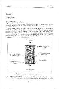
To obtain a high-efficiency pairing accelerator, one must consider issues such as: algorithm selection, top architecture, parallelism, resource sharing and efficient realization of the underlying field arithmetic. Algorithm comparison: The most attractive advantage of using Alg. 2 instead of Alg. 1 is that it takes half iterations in the accumulative multiplication stage. However, a lower complexity of the data-path for final exponentiation can be gained when using Alg. 1 considering that its final exponentiation is much simpler than that of Alg. 2. Both algorithms are realized in our experiments. Top architecture: There are basically two kinds of structures. The first one is the traditional stored-program machine (SPM), which contains three functional units: a processor, a controller, and memory [20]. The processor includes registers, datapaths, control lines and ALU. The controller should be capable of steering data to the proper destination according to the instruction. The memory is used to store instructions and data. To adopt such an architecture, the designer needs to develop ALU according to the operations necessary for pairing, and accordingly build the instruction set. Since the intermediate operands of pairing are data-dependent and most of the field operations can not be completed in a single or small number of clock cycles, it’s not suitable to be pipelined. Moreover, in program-directed operations, instructions are synchronously fetched, decoded and executed, which will deter the operation speed of the accelerator of pairing because of the overhead of communication between memory and the processor. Alternatively, the pairing processor can be constructed via a main controller, interconnection networks, register files and ALU. The controller may be designed as a finite state machine (FSM), scheduling the computation tasks, i.e., it can generate the stimulate signals and select signals switching operands for ALU. The intermediate results will be stored in the register files in order to eliminate the overhead of communication between memory and ALU. We adopt the second architecture for our pairing processor, as shown in Fig. 1. Parallelism and sharing resources: One advantage of hardware implementation is that it supports parallel computations and provides high operation speed as long as multiple operations can be performed at the same time. In the first stage of both algorithms, the computations C · A and α · v can be completed simultaneously. Additionally, in the second stage of both algorithms, by multiplying the conjugates of the elements in extension fields F24m and F22m , the inversion of extension fields can be transformed into one inversion in F2m and several multiplications in F2m , F22m and F24m . We use one special extension field multiplier, namely CA in Fig. 1, to perform the multiplications involved in both stages. The multiplier CA can be optimized to obtain a compact design by sharing some combinational circuits among several multipliers in F2m in case of the same 6
Operation outputs
Register Files Reg
Reg
... ...
Reg
Reg
Main Controller
Interconnection Networks ... ...
Select
Operation inputs
Control
Arithmetic Logic Unit Accumulative multiplication
in
F2 m
x2 in F2 m
in
F2 m
y2 in F2 m
Squarer in F2 4m
Multiplier CA in
F24m
Multiplier 1 in F2m
Final exponentiation
c02
Squarer 1
c12
Squarer 2
in
in
F2 m F2 m
Multiplier 2 in F2 m
in F22m in F22m
Inverter in F2 m
Shared components
Figure 1: Top architecture of the accelerator of Tate pairing over binary fields. operand. The multiplier computing α · v in the first stage performs multiplications in F 2m involved in final exponentiation as well. Underlying field arithmetic: The underlying field F2m is constructed via the low Hamming weight irreducible polynomial, such as a trinomial or a pentanomial, by which reductions become simple. Squarer should not be shared since the multiplexers introduced are more expensive. Multiplier is the most significant component directly determining the performance of the accelerator, so it is imperative to implement it with high efficiency. Linear feedback shift register (LFSRs) structure is adopted in our MSD-serial multipliers. The multiplicative inversion in F2m is computed using Itoh-Tsujii algorithm. Since most intensive computations concentrate in the first stage, it requires that the multipliers inside the component CA and the multiplier performing α · v should have large digit sizes to achieve high operation speed. On the other hand, in order to decrease the resource utilization without loss of performance, the multipliers working only at the final exponentiation stage can be relatively slow, with small digit size.
5.1
Design of Arithmetic Logic Unit
In the following section, we briefly review the traditional technique computing squaring over the underlying field. Our main interest is to compute the multiplications C · A efficiently. In particular, we propose a method optimizing individual subfield multiplier to obtain a compact design of the extension field multiplier CA. Furthermore, we present two schemes for the multiplier CA in which a different number of multipliers are used. These two schemes are ported to an FPGA device. The optimal choices are made based on the product of latency by area. Finally, the simplifying technique for the final exponentiation in both algorithms is explained.
7
5.1.1
Squarer
P Pm−1 i 2 2i Squaring an element a = m−1 i=0 ai x . i=0 ai x ∈ F2m , where ai ∈ F2 , is ruled by the equation a = Since the underlying fields are constructed via irreducible trinomials or pentanomials, by replacing xm with xk + 1 or xk3 + xk2 + xk1 + 1, we can get the formulae computing the coefficients of a2 . The circuit complexity in terms of gate count is proportional to m. Further details can be found in [22]. Squaring over the extension fields F22m and F24m is relative easy and can be decomposed into several squarings in F2m . 5.1.2
Multiplier
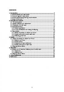
Digit serial multiplier, allowing the trade-off between timing and area, is more suitable for cryptographic applications with large operand sizes. There are two basic algorithms computing multiplications with polynomial basis representation in F2m , left-to-right and right-to-left. Even though it is claimed in [24] that the second algorithm is superior in term of low power, we find that less registers are needed when using the first algorithm because only partial product needs to be updated in each iteration besides the shift-in digits. However, both partial product and one operand must be updated in each iteration when using the second one. Therefore we adopt the left-to-right algorithm to derive the digit-serial multiplier. Let a(x) and b(x) be the two operands of the multiplication in F2m and let c(x) be the product. Suppose that the shift D bits are from a(x). Let n = min{l | l ∈ Z, l ≥ m, and D | l}. Let Pn−1 0 0 i 0 a = a0 = 0. The multiplier contains mainly i=0 ai x , where ai = ai if 0 ≤ i ≤ m − 1, otherwise PD−1 i two parts, XOR-AND arrays for computing s(x) = i=0 an−D+i xi b(x) mod fm (x) and LFSRs for computing c(x) ← c(x) + s(x). There are two candidates for the second part, see Fig. 2. The first approach is to compute xi b(x) mod fm (x) separately and the partial sum is kept in m bits. For the second one, the partial sum is kept in m + D bits before reduction. Even though less XOR gates are used in the second structure for an individual multiplier, these XOR-AND arrays can not be shared among different multipliers in F2m . Additionally, the wire density is increased significantly if D is chosen large. On the contrary, the first approach is more suitable to construct the extension field multiplier CA in F24m considering that the XOR arrays for xi b(x) mod fm (x) can be shared among different multipliers in F2m in case they share one operand, see Equation 6 and Fig. 3. The second advantage of the first structure is its low wire density which makes it easy for placing and routing. With the basis {1, s, t, st} of F24m over F2m , we may write A = w + zs + et where w, z ∈ F2m and e ∈ F2 . We set e = 1 in the accumulative stage and e = 0 in the final exponentiation stage. Let C = c0 + c1 s + c2 t + c3 st, ci ∈ F2m , be the partial product of C ← C · A. It it not suitable to apply Karatsuba-Ofman algorithm [23] directly to compute this extension field multiplication recursively since more underlying field multiplications would need to be calculated. However, we can use the same idea to simplify the computations of coefficients c01 and c03 (see Equation 6). C · (w + zs + et) = (c0 + c1 s + c2 t + c3 st)(w + zs + et) = c00 + c01 s + c02 t + c03 st,
(5)
where c00 = c0 w + c1 z + ec3
c01 = (c0 + c1 )(w + z) + c0 w + e(c2 + c3 )
c02 = c2 w + c3 z + e(c0 + c2 )
c03 = (c2 + c3 )(w + z) + c2 w + e(c1 + c3 )
(6)
Therefore, it takes only 6 F2m -multiplications for the computation of C · A, and all these 6 multiplications can be done simultaneously if 6 multipliers in F2m are adopted (See Fig. 4(a)). 8
(a) Structure 1
(b) Structure 2
Figure 2: Alternative structures for
PD−1 i=0
an−D+i xi b(x) mod fm (x).
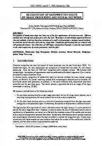
Figure 3: Two digit serial multipliers in F2239 with D = 4 sharing the component for mod f239 (x). 9
P3
i=0 x
i b(x)
w m
C0
C1
m
m
mul_1 in F m 2
mul_2 in F m 2
z
mul_3 in F m 2
e
m m m m
mul_4 in F m 2
mul_5 in F m 2
C0
C1
C2
C3
m
m
m
m
m
m
sel
C’ 0
sel
w
sel
z
m
C’ 1
mul_1 in F 2 m
C’ 2
mul_2 in F 2 m
mul_3 in F 2 m
C’ 3
mul_6 in F m 2
en
Reg
en
m m
m
C2
C3
Reg m
C’ 0
C ’1
e m
C’ 2
m
C ’3
(b) Scheme 2: 3 multipliers adopted
(a) Scheme 1: 6 multipliers adopted
Figure 4: Alternative schemes for CA.
Table 2: FPGA implementation results for the multipliers CA over F24×239 and F24×283 . Scheme 1 for F2239 # FF # LUT # CLB slices Clock period (ns) Latency (ns)
D=4 3664(4%) 7799(8%) 4268(9%) 9.61 576.6
# FF # LUT # CLB slices Clock period (ns) Latency (ns)
D=4 4324(4%) 9273(10%) 5070(11%) 9.84 698.6
D=8 3664(4%) 13508(15%) 7094(16%) 9.98 299.4
Scheme 2 for F2239
D = 16 3664(4%) 20744(23%)) 10722(24%)) 9.99 149.9
D=4 2675(3%) 5580(6%) 3617(8%) 9.86 1182.8
Scheme 1 for F2283 D=8 4348(4%) 16060(18%) 8416(19%) 9.98 359.3
D=8 2675(3%) 8439(9%) 5331(12%) 9.98 598.8
D = 16 2675(3%) 12075(13%) 7536(17%) 9.76 292.8
Scheme 2 for F2283
D = 16 4348(4%) 24729(28%) 12856(29%) 9.99 179.8
10
D=4 3159(3%) 6632(7%) 3046(6%) 8.89 1262.4
D=8 3171(3%) 10031(11%) 4483(10%) 9.99 719.3
D = 16 3171(3%) 14428(16%) 6306(14%) 9.98 359.3
Alternatively, if 3 multipliers are adopted in case of limited resources, the computation of C · A will take two multiplication rounds. In the first round, the first two coefficients of the product, namely c 00 and c01 , will be computed and stored in the registers. In the second round, the other two coefficients, namely c02 and c03 , will be computed (See Fig. 4(b)). To get the optimal choice in terms of low product of latency by area, both schemes of the special multipliers CA over F24×239 and F24×283 are ported to the same FPGA device, Xilinx XC2VP100-6FF-1704. The optimization goal is speed instead of area. Second, the hierarchy is not kept so that registers and XOR arrays can be saved considering that several underlying field multiplications share the same operands. Comparisons in terms of timing and area are demonstrated in Table 2. According to Table 2, Scheme 1 is always superior in terms of low product of latency by area. Hence we adopt 6 multipliers in the extension field multiplier CA for our pairing accelerator so that the multiplication C · A can be completed in one underlying field multiplication round. 5.1.3
Inverter
The inversion in F24m involved in the final exponentiation can be transformed into one inversion in F2m and several multiplications in F2m (the transforming procedure is explained in details in Sec. 5.2). Therefore, we only need to implement one inverter in F2m . Itoh-Tsujii’s algorithm [25] is adopted in our realizations. It takes blog2 (m − 1)c + HW (m − 1) − 1
(7)
multiplications in F2m to complete one inversion, where HW (m − 1) denotes the Hamming weight of m − 1.
5.2
Simplifying the Data-path for the Final Exponentiation
Let C = C1 + C2 t with C1 , C2 ∈ F22m . Using subfield arithmetic and repeated norm calculations, we 2m may compute C 2 −1 . Letting C12 + C1 C2 + C22 s = c0 + c1 s with c0 , c1 ∈ F2m , a straight calculation shows C2
2m −1
=
1 · (c0 + c1 (s + 1))(C12 + C22 (1 + s) + C22 t), c20 + c0 c1 + c21
where the total cost of the above computations is 1 F2m -inversion plus 12 F2m -multiplications. That is, we need 4 F2m -multiplications (1 F22m -multiplication for C1 C2 and 1 F2m -multiplication for c0 c1 ) for the denominator c20 + c0 c1 + c21 , 2 F2m -multiplications for c2 +c 1c +c2 · (c0 + c1 (s + 1)), and 6 F2m 0
0 1
1
multiplications (2 F22m -multiplications) which come from the final multiplication by C12 + C22 (1 + s) + C22 t. Therefore only six multiplication units (for parallel processing) are needed here and one can reuse the same arithmetic units as shown in Fig. 5 for multiplications, and thus the additional cost of the final exponentiation is the inversion circuit for computing c2 +c 1c +c2 . 0
0 1
In Algorithm 2, we have more complicated final exponentiation, where M = m+1 2
m+1 2
1
24m −1 |Eb (F2m )|
=
24m −1 2m ±2
m+1 2 +1
= (22m − 1)(2m ∓ 2 + 1) and T = 2 ± 1. Here we should be cautious about appropriate sign m+1 m+1 of T . The original definition of T [9] is T = 2m − N = ∓2 2 − 1. However when T = −2 2 − 1, one computes (−T ){(P ) − (O))} which gives an inverse of the rational function corresponding to T {(P ) − (O))}, so the exponents should be changed to −T in this case. When m = 239 and b = 1, m+1 m+1 we have |Eb (F2m )| = 2239 − 2120 + 1. In this case we get M T = (22m − 1)(2m + 2 2 + 1)(2 2 − 1) with m = 239. Also when m = 283 and b = 0, we have |Eb (F2m )| = 2283 − 2142 + 1 and thus we have m+1 m+1 the same form of M T = (22m − 1)(2m + 2 2 + 1)(2 2 − 1) with m = 283. 11
Suppose z is in GF (24m ) such that z = w 2 and thus we get z −1 = z m z (2 +1+2
5.3
m+1 m+1 2 )(2 2 −1)
=
22m
2m −1
for some w ∈ F24m . Then z 2
. Moreover from 1 = z
m z (2 +1+2
m+1 2 )2m
22m +1
= z
2m +1
= w2
4m −1
m+1 m+1 (2m +1+2 2 )(2m +1−2 2 )
=1
, we get
. Therefore the exponent M T can be interpreted as:
M T = (22m − 1)(2m + 2
m+1 2
= (22m − 1)(2m + 2
m+1 2
+ 1)(2
m+1 2
− 1)
+ 1)2m
(8)
Parameter Choices for ALU
In Fig. 5, we provide the timing diagram of scheduling computations for pairing according to Algorithm 1. Additions and squarings realized via combinational circuits need not to be taken into account for estimating the latency.
Figure 5: Timing diagram of scheduling computations according to Alg. 1. Let ∆1 denote the latency for one computation of Tate pairing using Alg. 1 and let T clk denote the clock period. Let D1 denote the digit size of multipliers inside CA and Multiplier 1; D2 denote the size of Multiplier 2; and D3 denote the digit size of multiplier inside the inverter. The notations of T1 , T2 , T3 are specified in Fig. 5. Then we can estimate the latency for computing one Tate pairing using Alg. 1 as follows: ∆1 = (m + 2)(T1 + 2) + 3T2 + T3 + 8
(9)
where T1 = dm/D1 eTclk , T2 = dm/D2 eTclk . Two extra clock cycles are required for the register read/write operations. In case of F2239 , it takes around 239 clock cycles for exponentiation and 12 multiplications in case of computing c2 each cycle. However the latency for exponentiation needs 4 to be shortened. We compute c2 in each cycle so that 60 cycles are necessary to complete the exponentiation in the inversion of F2239 . Then T3 ≈ (60 + 12 · d239/D3 e)Tclk . Similarly T3 ≈ (71 + 11 · d283/D3 e)Tclk for F2283 . If we choose D1 = 16, D2 = 4 and D3 = 8, the time spent on final exponentiation is 10.3% of accumulative multiplications. However if we choose D 3 = 4 and keep the same value of D1 and D2 , the time for final exponentiation is 23.8% of accumulative multiplication. So we choose D1 : D2 : D3 = 4 : 1 : 2 for both F2239 and F2283 . For Alg. 2, the computation of C M T needs to be additionally taken into account for latency 4 estimation, see Equation 8. We use the component computing C 2 each cycle for the extension field 12
exponentiation, and one extension field multiplication with two operands in F24m can be completed by CA in two underlying field multiplication rounds. Then, we use the following equation to estimate the latency of pairing for Alg. 2, ∆2 =
m+5 (T1 + 2) + 3T2 + T3 + T4 + 8; 2
T4 =
m+1 Tclk + 4(T1 + 2) 2
(10)
where T4 denotes the latency for C M T . We use the same ratio of D1 , D2 and D3 as Alg. 1.
5.4
Results and Comparisons with Previous Work
The target device for our implementations is Xilinx XC2VP100-6FF-1704. For Alg. 1, the digit size of multipliers inside CA is chosen as 16 and 32 for both F2239 and F2283 . For Alg. 2, due to the limitation of resources, the digit size D1 is chosen as 16. The results after placing and routing via Xilinx ISE-7.1 are summarized in Table 3. Table 3: Performance and cost of Tate pairing accelerators on elliptic curves over F 2239 and F2283 using both algorithms. # FF
Alg. 1
F2239 , F2239 , F2283 , F2283 ,
Alg. 2
F2239 , D1 = 16 F2283 , D1 = 16
D1 D1 D1 D1
= 16 = 32 = 16 = 32
10,981 11,077 12,995 13,007
(12%) (12%) (14%) (14%)
14,226 (16%) 16,563 (18%)
# LUT 34,499 59,971 42,997 72,961
(12%) (68%) (48%) (82%)
48,895 (55%) 64,845 (73%)
# CLB slices
f (MHz)
Latency (µs)
(41%) (71%) (51%) (85%)
100 83 84 72
47 33 76 49
25,487 (57%) 33,252 (75%)
84 56
34 70
18,202 31,719 22,726 37,803
If the digit sizes are chosen the same for both algorithms, the latency of Alg. 2 is shorter than Alg. 1. However more resources are utilized for Alg. 2 because the multiple squarers in F 24m are adopted for C M T and more complicated datapath in final exponentiation can not be avoided so that the critical path is longer than Algorithm 1. Compared with other researchers’ works [1, 3, 4], almost at the same level of security strength, our Tate pairing accelerators can run 15-to-25 times as fast as theirs on average. See Table 4, where D denotes the digit size of multipliers working in the accumulative stage. In [1], the pairing accelerator for the elliptic curve over F397 with k = 6 is realized via a larger FPGA device, Xilinx XC2VP125 with 55,616 slices. Karatsuba-Ofman’s method [23] is used to construct the multiplier in F 36m . To achieve the full power of parallel computation for such a large extension field multiplication, 18 multipliers in F3m are necessary. Due to the limitation of resources, the digit sizes of underlying field multipliers can not be large so they select D = 4. The cost is 60% of 55616 slices for the multiplier in F36×97 . For comparison it costs only 10,722 slices for our multiplier CA in F24×239 where D = 16. No exact results for the whole accelerator of pairing are provided in [1], but it is claimed that 100% of resources are utilized. So the cost is around 55,616 CLB slices. The operation frequency is 10MHz and it takes 850 µs for one pairing. Our pairing accelerator on the elliptic curve over F 2239 can run 25 times faster. In [3], a smaller device, Xilinx XC2VP4FF672-6 with 4928 slices is chosen as the target device. The cubic field arithmetic is realized as a kind of co-processor via FPGA, which is controlled by a more general purpose processor, i.e., the top architecture is a stored-program machine (SPM) as described previously. Their field arithmetic co-processor contains only one polynomial basis multiplier with digit size D = 4 so that multiplications are performed sequentially, i.e., at least 18 subfield 13
Table 4: Comparisons with Peer researchers’ FPGA implementations with almost the same security strength.
[1]
Curves
Underlying fields
MOV Security
Controller
# CLB slices
Digit size D
f(MHz)
Latency (µs)
Elliptic
F397
922
Hardwired logic
55,616
4
10
850
[3]
Elliptic
F397
922
Microprocessor
4,481
4
150
432
[4]
Hyperelliptic
F2103
1236
Hardwired logic
43,986
16
32
749
Alg. 2
Elliptic
F2239
956
Hardwired logic
25,287
16
84
34
Alg. 1
Elliptic
F2283
1132
Hardwired logic
37,803
32
72
49
multiplication rounds are necessary for each iteration of the accumulative multiplication. In contrast, our processor support parallel computation of multiplications in F2m and the digit sizes we used are much larger than the ones in [3]. The latency for one pairing of our accelerator over F 2239 is only 34 µs. The latency of the design by Grabher et al. [3] is at least 432 µs. At the same time, our resource utilization is only 5 times larger as theirs. Ronan et al. [4] have implemented Tate pairing accelerator on the hyperelliptic curve over binary field using the device Xilinx XC2VP125 which is tha same as the one used in [1]. They chose a smaller underlying field F2103 and a larger embedding degree k = 12. However, in each iteration of accumulative multiplication stage, 16 multiplications in F2m and 1 multiplication in F212m need to be computed. These 16 subfield multiplications must be completed before the accumulative multiplication in F212m . Note that, in [4], one multiplication in F212m is realized as 54 multiplications in F2m using Karatsuba’s method. In our case, we choose a larger underlying field F 2283 and smaller embedding degree k = 4 so that the computations of accumulative multiplications becomes much simpler and only 7 multiplications in F2m are involved each round and these multiplications can be performed in parallel. The shortest latency for one pairing of Ronan et al’s is 749 µs and 50,893 slices are used. Our accelerator can run 15.6 times as fast as theirs whereas the resource utilization is only 37,803 slices, see Table 4.
6
Conclusions
We investigated the FPGA implementations of Tate pairing on supersingular elliptic curves over binary fields with embedding degree k = 4. We adopted two top algorithms computing pairing by which full power of parallel computations can be exploited with less resource utilization than in designs of other researchers. We performed security analysis for different curves over binary and cubic fields by which we can choose two binary fields F2239 and F2283 for our experiments to achieve almost the same security strength as others. Besides the superiority of top algorithms, we also proposed an optimization method to obtain a compact design of the extension field multiplier CA by sharing some combinational circuits among several individual subfield multipliers in F2m in case of one shared operand. Furthermore we compared two schemes with a different number of multipliers in F 2m for CA to get the optimal choice. The controller is implemented via hardwired logic to eliminate the overhead of instruction fetching and decoding, particularly for the simple operations such as additions and squarings. The technique simplifying the final exponentiations for both algorithms are addressed. Finally the implementations are further optimized by optimal parameter choices for ALU. Compared with other researchers’ work, our pairing processors are more efficient in terms of the product of latency by area. In particular, our accelerators can outperform earlier designs by a factor of 15-to-25 in terms of the total execution time. 14
References [1] T. Kerins, W.P. Marnane, E.M. Popovici, and P.S.L.M. Barreto, “Efficient hardware for the Tate pairing calculation in charateristic three”, CHES 2005, Lecture Notes in Computer Science, vol. 3659, pp. 412–426, 2005. [2] T. Kerins, E.M. Popovici, and W.P. Marnane, “Algorithms and architectures for use in FPGA implementations of Identity Based Encryption Schemes”, In Field Programmable Logic and Applications - FPL 2004, Lecture Notes in Computer Science, vol. 3203, pp. 74-83, 2004. [3] P. Grabher and D. Page, “Hardware acceleration of the Tate pairing in charateristic three”, CHES 2005, Lecture Notes in Computer Science, vol. 3659, pp. 398 - 411. [4] R. Ronan, C.O. Eigeartaigh, C. Murphy, M. Scott, T. Kerins, and W.P. Marnane, “A dedicated processor for the Eta pairing”, preprint available at http://eprint.iacr.org/2005/330.pdf. [5] R. Granger, D. Page, and M. Stam, “Hardware and software normal basis arithmetic for pairing based cryptography in characteristic three”, IEEE Trans. on Computers, vol. 54, pp. 852–860, 2005. [6] R. Granger, D. Page, and M. Stam, “On small characteristic algebraic tori in pairing based cryptography,” preprint available at http://eprint.iacr.org/2004/132.pdf, 2004. [7] I. Duursma and H. Lee, “Tate pairing implementation for hyperelliptic curves y 2 = xp − x + d”, Asiacrypt 2003, Lecture Notes in Computer Science, vol. 2894, pp. 111–123, 2003. [8] P. Barreto, H. Kim, B. Lynn, and M. Scott, “Efficient algorithms for pairing based cryptosystems”, Crypto 2002, Lecture Notes in Computer Science, vol. 2442, pp. 354–368, 2002. [9] P. Barreto, S. Galbraith, C. O’hEigeartaigh, and M. Scott, “Efficient pairing computation on supersingular abelian varieties,” preprint available at http://eprint.iacr.org/2004/375.pdf, 2004. [10] P. Barreto, “A note on efficient computation of cube roots in characteristic 3,” preprint available at http://eprint.iacr.org/2004/305.pdf, 2004. [11] S. Kwon, “Efficient Tate pairing computation for supersingular elliptic curves over binary fields,” preprint available at http://eprint.iacr.org/2004/303.pdf, 2004. [12] S. Galbraith, K. Harrison, and D. Soldera, “Implementing the Tate pairing,” ANTS 2002, Lecture Notes in Computer Science, vol. 2369, pp. 324–337, 2002. [13] V. Miller, “Short programs for functions on curves,” unpublished manuscript, 1986. [14] A.J. Menezes, Elliptic Curve Public Key Cryptosystems, Kluwer Academic Publisher, 1993. [15] A. Shamir, “Identity-based cryptosystems and signature schemes,” Crypto 1985, Lecture Notes in Computer Science, vol. 196, pp. 47–53, 1985. [16] K. Fong, D. Hankerson, J. L´opez, and A. Menezes, “Field inversion and point halving revisited,” Technical Report CORR 2003-18, Univ. of Waterloo, 2003. [17] D. Boneh and M. Franklin, “Identity based encryption from the Weil pairing,” Crypto 2001, Lecture Notes in Computer Science, vol. 2139, pp. 213–229, 2001.
15
[18] R. Sakai, K. Ohgishi, and M. Kasahara, “Cryptosystems based on pairing,” SICS 2000, Symposium on Cryptography and Information Security, pp. 26–28, 2000. [19] I.F. Blake, G. Seroussi, and N.G. Smart, Advances in elliptic curve cryptography, Cambridge University Press, 2005. [20] M.D. Ciletti, Advanced digital design with the Verilog HDL, Prentice Hall, 2004. [21] T. Wollinger, “Software and Hardware Implementation of Hyperelliptic Curve Cryptography”, Ph. D Thesis, Bochum : Europ¨aischer University, 2004. [22] G. Orlando and C. Paar, “A high-performance reconfigurable elliptic curve processor for GF (2m )”, CHES 2000, vol. 1965, pp. 41-56, 2000. [23] A. Karatsuba and Y. Ofman, “Multiplication on many-digit numbers by automatic computers”, Translation in Physics-Doklady, vol 7, pp. 595-596, 1963. [24] L. Song and K.K. Parhi, “Efficient Finite Field Serial/Parallel Multiplication”, Proceedings of International Conference on Application Specific Systems, Achitectures and Processors - ASAP’96, pp. 72-82, 1996. [25] T. Itoh and S. Tsujii, “A fast algorithm for computing multiplicative inverses in GF (2 m ) using normal bases”, Information and Computation, vol. 78, pp. 171-177, 1988.
16