Malaysian Journal of Computer Science, Vol. 11 No. 2, December 1998, pp. 1-7
EASILY TESTABLE ARRAY MULTIPLIER DESIGN USING VHDL
S. M. Aziz Department of Electrical and Electronic Eng. Bangladesh University of Eng. & Technology Dhaka-1000, Bangladesh Fax: +880-2-863026 email:
[email protected]
Iftekhar Ahmed Faculty of Engineering University of Telecom Malaysia 75450 Bukit Beruang Melaka, Malaysia email:
[email protected]
C-testable [9-13], i.e., they can be tested for all single stuck-at faults with a constant number of test vectors irrespective of the size of the operands. Although stuck-at fault models cannot adequately model transistor stuck-on and stuck-open faults [14, 15], it is possible to derive equivalent stuck-at test sets for logic gates to cover transistor stuck-on and stuck-open faults [16]. Since the number of test vectors is constant for any multiplier size, the test generation time for the proposed designs is considerably small.
ABSTRACT Presents the design of variable array multipliers using VHDL. Multipliers of various operand sizes for different target processes can be implemented using the proposed VHDL based approach. The multipliers will be testable with a constant number of test vectors irrespective of the operand word lengths. A fast test pattern generator is also developed for simulation of the multiplier designs and subsequent testing of the fabricated chips. Keywords:
1.0
VHDL, Multiplier, Parameterizable
C-testable,
In the next section the multiplier architecture is presented. Section 3 presents the testability of the multiplier. The VHDL model for the multiplier is given in Section 4.
INTRODUCTION 2.0
With the continuing developments of VLSI technologies and tremendous shrinkage of process features, the need to develop process independent chip design tools are growing [1, 2]. The use of a hardware description language (HDL) for integrated circuit design eliminates the need to worry about process design rules at the early stages of design [2, 3]. This reduces the design complexity and time required to complete chip designs. This is very important since vendors need to market their products in the shortest possible time. The fact that such high level designs can be implemented on a variety of target processes reduces the design cost as well.
ARCHITECTURE
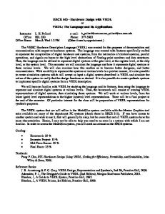
The architecture of the multiplier is shown in Fig. 1. It is based on the modified Booth algorithm [12-13], [17-18]. This algorithm considers the operands as two’s complement numbers and gives the product output in two’s complement form. It reduces the number of partial products by almost a factor of two compared to the straightforward carry-save array multipliers [10, 11]. In the architecture of Fig. 1, the explicit sign extension circuitry has been eliminated by recoding the most significant bits (MSBs) of the partial products as a two’s complement number [19, 20]. The multiplicand and the multiplier are denoted by X and Y respectively, where X = ( x5 x4 x3 x2 x1 x0 ) and Y= ( y7 y6 y5 y4 y3 y2 y1 y0 ) are chosen for convenience.
Multipliers are often one of the key elements in single chip digital information processors [4, 5]. The different modules within such processors have to be tried out for various architectures in order to find an optimal speed and area. Since it is time consuming to verify many possible layouts for each module, one approach is to use software packages called module generators or silicon compilers to provide fast and efficient design of parameterized modules. The multiplier compilers presented in [6] and [7] generate parameterizable layout for MOS technology. The technology independence of the compiler presented in [8] is limited by the requirement that the leaf cells have to be recharacterized in the new technology. The aim of this paper is to present the design of totally process independent VLSI array multipliers of variable size (parameterizable) using VHDL. The multipliers are made
Although the architecture shown in Fig. 1 is that of a 6 by 8 bit multiplier, the regularity of the architecture enables one to draw larger multipliers quite easily. The multiplier of Fig. 1 contains six extra inputs x-1, y-1, e1, e2, e3, e4 for enhancing the testability of the multiplier. For normal multiplication operation these inputs should have the following logic levels: x-1 = 0, y-1 = 0, e1 = e2 = 0 and e3 = e4 = 1. The architecture of Fig. 1 is very regular consisting of only three different leaf cells, namely, the modified Booth encoder (BE), multiplexer-complementers and the adders. The final adders often employ some form of fast carry propagation scheme and are implemented differently than the carry-save adders (FA) used in the array [21]. 1
Aziz and Ahmed
Booth Encoder y-1 y0 y1 y2 y3
e4 e3
e2
x5
x4
x3
x2
x1
x0 x-1 e1
CM, K1, K2
B E1
Multiplexercomplementer
PPi B E2
FA- Full adder
p0
FA
y4 y5
B E3
p1 FA
y6 y7
p2
B E4 p3 FA
Final adders
p13
p12
p11
p10
p9
p8
p7
p6
p5
p4
Fig. 1: Architecture of the multiplier with recoded sign bits (Horizontal signals are omitted for clarity) However, both these adders perform the same logic functions and therefore may be regarded to be the same from the point of view of logic functionality. Each modified Booth encoder scans three multiplier bits and generates three controls signals K1, K2 and CM. The multiplexer-complementers use these signals to generate the proper version of the multiplicand as a partial product (PPi) according to the modified Booth recoding scheme [18]. The logic functions performed by the various cells of the multiplier of Fig. 1 are expressed by the following equations. Note that Zi is the output of the multiplexer and PPi is the partial product generated.
Adders:
3.0
(1)
K 2 = yi - 1 yi yi + 1 + yi - 1 yi yi + 1
(2)
CM = yi - 1 yi + 1 + yi yi + 1
(3)
Multiplexer-complementer:
Zi = K 1 xi + K 2 xi - 1
(4)
PPi = CM ⊕ Zi
(5)
(6)
COUT = AB + BC + CA
(7)
TESTABILITY OF THE MULTIPLIER
Multipliers of any size based on the architecture presented in Fig. 1 can be made testable using a set of only 19 test vectors shown in Table 1. In this table, an 8-bit multiplicand (X) and an 8-bit multiplier (Y) are shown. The underlined bits denote the extensions required for larger multiplier [13]. For example, t9 shows that X=0101 0101 and Y=1100 1100. The vector X will be 010101010 and 0101010101 for 9-bit and 10-bit words respectively. Note that extensions are made to the right side. The vector Y will be 0011001100 and 110011001100 for 10-bit and 12-bit words respectively. In this case extensions are made to the left side. All the adders are tested exhaustively using the vectors listed in Table 1. However, the modified Booth encoders and multiplexers are tested for stuck-at faults. This is because the complexity of exhaustively testing the later is enormous.
Modified Booth encoders:
K 1 = yi - 1 ⊕ yi
SUM = A ⊕ B ⊕ C
All the carry-save full adders in the multiplier of Fig. 1 are tested exhaustively by vectors t1 - t12. Exhaustive testing of 2
Easily Testable Array Multiplier Design Using VHDL
the final adders are accomplished by the vectors t1 - t16. Since the sum outputs of the adders are XOR function of the three inputs, and both the outputs of all the array fulladders are cascaded through a number of such XOR gates up to the final adders, the propagation of a faulty output in any of the adders to the primary outputs is guaranteed [13].
3.1
The number of test vectors required is always 19, only their lengths vary with the multiplier size. Therefore, the test vectors for the proposed multipliers of variable operand word lengths can be generated using a simple program. A C++ program has been developed for test generation for variable multipliers. The pseudo-code for the test generation program is given below:
Table 1: Test vectors for the proposed multiplier x-1
Y
y-1
Test Generation for Variable Multipliers
Test vectors
X
e4e3e2e1
t1
0000 0000*
0
0000 0000
0
0000
#define T_Length 19
t2
1000 0000
0
0101 0101
0
0000
t3
1111 1111
1
0101 0101
0
1111
t4
1000 0000
0
1010 1010
1
1111
struct test_c { unsigned long X, Y; unsigned int Y_1, E; };
t5
0000 0000
0
1111 1111
0
1100
t6
0000 0000
0
0011 0011
1
0011
t7
1111 1111
1
0101 0011
0
0011
t8
1111 1111
1
0100 0100
1
1100
t9
0101 0101
0
1100 1100
1
0110
t10
01010101
0
0011 0011
0
1001
t11
1111 1111
1
0011 0011
0
0011
t12
1111 1111
1
1100 1100
1
1100
t13
0000 0000
0
1010 1010
1
1100
t14
1111 1111
1
1010 1010
1
0000
t15
111 11111
0
1001 1001
1
1111
t16
111 11111
0
0110 0110
0
0000
t17
0000 0000
0
0110 0110
0
1111
t18
1111 1111
1
1001 1001
1
1001
t19
1111 1111
1
1111 1111
1
0000
//Pseudo-code for the C-test generation program
// X, Y operands // Y_1, test inputs E
void main() { struct test_c T[19]; int i, j, size_x, size_y; unsigned long v; unsigned int s; for (i=0; i