A Far-field Pattern Separation Approach for the Synthesis of Directional Modulation Transmitter Arrays Yuan Ding*, and Vincent Fusco The Institute of Electronics, Communications and Information Technology (ECIT), Queen’s University Belfast, Belfast, United Kingdom, BT3 9DT E-mail:
[email protected];
[email protected]
Abstract In this paper a far-field power pattern separation approach is proposed for the synthesis of directional modulation (DM) transmitter arrays. Separation into information pattern and interference patterns is enabled by far-field pattern null steering. Compared with other DM synthesis methods, e.g., BER-driven DM optimization and orthogonal vector injection, this approach facilitates manipulation of artificial interference spatial distributions. With such capability more interference power can be projected into those most vulnerable to eavesdropping spatial directions in free space, i.e., the information sidelobes. In such a fashion information leaked through radiation sidelobes can be effectively mitigated in a transmitter power efficient manner. The proposed synthesis approach is further validated via bit error rate (BER) simulations.
1. Introduction Directional modulation (DM) technology, as a promising physical layer security means for wireless communication in free space, has attracted extensive researchers in recent years. Different to the conventional wireless transmitters, which broadcast identical copies of information into the whole space, subject to power scaling, DM-enabled transmitters have the capability of scrambling information formats, i.e., the constellation patterns in IQ space for modern digital modulations, along each spatial directions other than a pre-specified secure communication direction where no distortion will occur. This controlled means for information distortion imposes a great challenge onto the interception by potential malicious eavesdroppers sited away from the desired direction. Several DM transmitter synthesis approaches, based on the actively driven antenna arrays, has been proposed and studied, [1-6]. In [1, 2] by linking the bit error rate (BER) performance and the DM array excitation settings, a fit-for-purpose cost function can be established. Another universal synthesis method, which uses vector representations of DM systems and the orthogonal vector concept, was described in [3]. Here no constraints, other than the necessary and sufficient conditions in (5) and (6) in [3] for achieving DM characteristics, are imposed. The first attempt to confine far-field radiation patterns of DM transmitters was reported in [4]. This approach, as well as its extension in [5], provides some control on DM radiation characteristics. In this paper by virtue of the far-field null steering approach, the DM far-field radiation patterns can be separated into information patterns, which describe information energy projected along each spatial direction, and interference patterns, which represent disturbance on genuine information. By this separation methodology, described in this paper for the first time, we can identify the spatial distribution of information transmission and hence focus interference energy into the most vulnerable directions, i.e., information sidelobes, and in doing so submerge leaked information along unwanted directions.
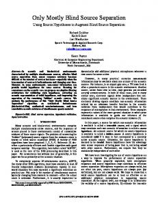
2. The Proposed Far-field Pattern Separation DM Synthesis Approach In this section the procedure of the proposed far-field pattern separation DM synthesis approach is presented below for an N-by-1 uniformly half wavelength spaced DM transmitter array, shown in Fig. 1. 1) Select a set of array excitations, P, that generate a far-field radiation pattern with main beam pointing to the desired secure communication direction θ0. Hereafter we term this generated far-field radiation pattern as the information pattern. Normally we choose excitations with uniform magnitudes and progressive phases, i.e., −n·k·d·cosθ0, (n = −(N−1)/2, −(N−1)/2+1, …, (N−1)/2). k is the wave number, and d denotes the array element spacing, λ/2 in this paper. The array phase center is chosen as its geometric center. In Fig. 2(a) an example of a normalized information pattern is depicted for N = 5 and θ0 = 120º. It is assumed
978-1-4673-5225-3/14/$31.00 ©2014 IEEE
that the active element patterns (AEPs) of each array element are identical and are isotropic. Q Q Legitimate Receiver
I
Eavesdropper
I Constellation Point in IQ Space
λ: Wavelength Array Element
λ/2
λ/2
λ/2
θ0
Information Pattern
…………… ele. 1
ele. 2
ele. 3
Interference Patterns
Phase Center
ele. N-1
ele. N
Figure 1. An N-by-1 uniformly half wavelength spaced DM transmitter array. The information pattern and interference patterns are illustrated. The interference distorts signal constellations along all spatial directions other than the prescribed direction θ0.
2) Find (N−1) spatial directions of sidelobes in the information pattern obtained in the step 1). Then, similar to the step 1), get (N−1) sets of excitations, Ai = [Ai1 Ai2 … AiN]T, (i = 1, 2, …, N−1), that generate farfield radiation patterns with main beams towards the (N−1) information sidelobe directions respectively. ‘[·]T’ is the vector transpose operator. In Fig. 2(a) the four radiation power patterns corresponding to each of the four sidelobes in the example information pattern are illustrated. In this example, the power of each main beam is 3 dB larger than that of its corresponding sidelobe. 3) Alter each of the obtained (N−1) sets of excitations Ai to steer far-field pattern nulls to the desired secure communication direction θ0. We choose the power pattern projection method stated in [6] to steer the nulls. Briefly speaking, the required optimum excitation weights Bi, satisfying main beam and null directions and total power consumption, can be obtain via (1),
Bi = [ Bi1
T
Bi 2 L BiN ] = I N − C −1C Ai
(1) − jnkd cosθ
3 0
3 0
−10
−10
Magnitude (dB)
Magnitude (dB)
0 Here IN denotes the N-by-N identity matrix, and C is a 1-by-N vector with the nth element of e . −1 The ‘[·] ’ in (1) is the Moor-Penrose pseudoinverse operator, returning an N-by-1 vector in this case. By operating this pattern projection in (1), nulls in the (N−1) far-field patterns obtained in the step 2) are steered to the desired communication direction θ0, while the main beams are kept unchanged along each of the sidelobe directions in the information pattern. These resultant far-field patterns associated with array excitations Bi are labelled as interference patterns in this paper. Fig. 2(b) illustrates the four interference patterns obtained, with the help of (1), from the corresponding patterns in Fig. 2(a).
−20
−30
−40
−20
−30
0º
30º
60º
90º
120º
150º
Spatial Direction θ Information Pattern Far-field Patterns Generated by Ai, with Main Beams Pointing to the Each Sidelobe Direction
(a)
180º
−40
0º
30º
60º
90º
120º
150º
180º
Spatial Direction θ Information Pattern Interference Patterns Generated by Bi, Corresponding to the Each Information Sidelobe
(b)
Figure 2. (a). The information pattern obtained in the step 1) and four far-field patterns generated by Ai obtained in the step 2); (b). The information pattern obtained in the step 1) and four interference patterns generated by Bi obtained in the step 3).
4) With the excitations P and Bi, associated with information pattern and interference patterns respectively, the excitations, Sm, for the mth symbol, Dm, in a data stream transmission in a DM system can be synthesized via (2), N −1
Sm = Dm ⋅ P + ∑ ( Rim ⋅ Bi )
(2)
i =1
Rim is a random complex number with constraints imposed by the practical hardware limitations in the DM transmitter. Since the (N−1) interference patterns have nulls along the desired communication direction θ0, the magnitude and phase relations in Dm are well preserved in the detected signal along θ0. Whereas the received signals along other spatial directions are randomly and dynamically corrupted by interference, especially along the information sidelobe directions. Using the excitations P and Bi associated with example patterns in Fig. 2(b), the excitations, Sm, for a DM array, when four unique QPSK symbols are transmitted, are obtained and listed in Table 1. In this example, Rim is set to be unity magnitude with random phase. The corresponding far-field patterns of this example DM array are illustrated in Fig. 3. It can be clearly observed that only along θ0, 120º in this example, the magnitudes of the four QPSK symbols overlap each other, and their phases are 90° spaced, indicating that a standard QPSK constellation, i.e., a central symmetric square in IQ space, is formed. The constellation patterns detected in all other locations are scrambled. Table 1. The synthesized DM array excitations for four unique QPSK symbol transmissions shown in Fig. 3. Excitations Sm a m=1, Symbol ‘11’ m=2, Symbol ‘01’ m=3, Symbol ‘00’ m=4, Symbol ‘10’
Sm1 (×10−1) −1.912− j1.198 2.629− j1.830 0.610+ j1.554 −0.193+ j2.023
Sm2 (×10−1) −1.750+ j2.013 −1.090− j0.469 1.467− j0.707 −0.312+ j3.129
Sm3 (×10−1) 0.560+ j1.361 0.082+ j1.614 −3.131− j1.920 1.898− j2.190
3
Sm4 (×10−1) 1.871− j 0.231 0.767+ j1.277 -0.380+ j2.786 −1.942− j0.218 a. Sm = [Sm1
Sm5 (×10−1) −2.355− j 0.891 2.778− j1.770 −0.163+ j1.751 −1.633+ j1.228 Sm2 Sm3 Sm4 Sm5]T
180º
0
135º
45º
−10 Phase
Magnitude (dB)
90º
0º −45º
−20 −90º −135º
−30
0º
30º
60º
90º
120º
150º
180º
−180º
0º
30º
60º
For Symbol ‘11’
For Symbol ‘01’ For Symbol ‘10’
For Symbol ‘00’
90º
120º
150º
180º
Spatial Direction θ
Spatial Direction θ
For Symbol ‘11’
For Symbol ‘01’ For Symbol ‘10’
For Symbol ‘00’
(a)
(b)
Figure 3. The far-field (a) magnitude and (b) phase patterns of the example synthesized DM array for four unique QPSK symbols. Array excitations for each symbols are listed in the Table 1.
3. BER Simulation Results To be consistent with the examples in Section 2, we choose the same information pattern and interference patterns in Fig. 2(b) to construct a dynamic DM system, [3], which is synthesized by updating Rim in (2) for each m. Similar to the examples in Section 2, the absolute value of Rim is confined to be unity, and only its phase is updated randomly. To assess the secrecy performance of the synthesized dynamic DM system, the BER simulations are calculated through a QPSK data stream with 106 random symbols. Gray-coding is used throughout. The details of BER calculation can be found in [7]. In Fig. 4 BER spatial distributions for the synthesized dynamic DM system are depicted for signal to noise ratios (SNRs), along the desired secure communication direction θ0, i.e., 120º, of 12 dB and 22 dB respectively. The AWGN contribution is identical in all spatial directions for each case. For comparison the BER performance of the conventional system, which denotes the transmitter that radiates only through the information pattern, and no interference patterns are present, is also presented. It can be concluded that DM functionality, enabled by the energy radiated through the
interference patterns, can narrow the decodable spatial region and suppress BER sidelobes effectively, especially under high SNR scenarios. 100
100
10−1
10−1 SNR = 12 dB BER
10−2
BER
10−2
10−3
10−3
10−4
10−4
SNR = 22 dB DM system 10−5
DM system
Conventional system 0º
30º
60º
90º
120º
150º
180º
10−5
Conventional system 0º
30º
60º
90º
Spatial Direction θ
Spatial Direction θ
(a)
(b)
120º
150º
180º
Figure 4. Simulated BER spatial distributions for the dynamic DM and conventional QPSK systems under SNRs of (a) 12 dB and (b) 22 dB. QPSK data streams with 106 random symbols are used for simulation.
4. Conclusion In this paper it has been shown that DM transmitters can be synthesized by summing information pattern and interference patterns, which are orthogonal along the selected communication direction. This separation allows DM transmitters to focus interference into the most vulnerable directions, i.e., the information sidelobes, and thereby lower the possibility of information recovery by eavesdroppers located away from the desired communication direction.
5. Acknowledgments This work was sponsored by the Queen’s University of Belfast High Frequency Research Scholarship.
6. References 1. M. P. Daly and J. T. Bernhard, “Directional Modulation Technique for Phased Arrays,” IEEE Trans. Antennas Propagat., vol. 57, no. 9, pp. 2633-2640, Sept. 2009. 2. Y. Ding and V. Fusco, “BER Driven Synthesis for Directional Modulation Secured Wireless Communication,” International Journal of Microwave and Wireless Technologies. Available: http://dx.doi.org/10.1017/S175 9078713000913. 3. Y. Ding and V. Fusco, “A Vector Approach for the Analysis and Synthesis of Directional Modulation Transmitters,” IEEE Trans. Antennas Propagat., vol. 62, no. 1, pp. 361-370, Jan. 2014. 4. Y. Ding and V. Fusco, “Directional Modulation Transmitter Radiation Pattern Considerations,” IET Microw., Antennas Propag., vol. 7, no. 15, pp. 1201-1206, Dec. 2013. 5. Y. Ding and V. Fusco, “Constraining Directional Modulation Transmitter Radiation Patterns,” IET Microw., Antennas Propag., submitted for publication. 6. Tung Sang Ng, “Generalized Array Pattern Synthesis Using the Projection Matrix,” IEE Proceedings Microw., Antennas Propag., vol. 132, no. 1, pp. 44-46, Feb. 1985. 7. Y. Ding and V. Fusco, “Establishing Metrics for Assessing the Performance of Directional Modulation Systems” IEEE Trans. Antennas Propagat., in press.