AbstractâRecent advances in sensor technology for muscle activity monitoring have resulted in the development of a coupled microphone-accelerometer ...
IEEE TRANSACTIONS ON BIOMEDICAL ENGINEERING, VOL. 52, NO. 9, SEPTEMBER 2005
1493
A Mathematical Model for Source Separation of MMG Signals Recorded With a Coupled Microphone-Accelerometer Sensor Pair Jorge Silva*, Student Member, IEEE, and Tom Chau, Senior Member, IEEE
Abstract—Recent advances in sensor technology for muscle activity monitoring have resulted in the development of a coupled microphone-accelerometer sensor pair for physiological acoustic signal recording. This sensor can be used to eliminate interfering sources in practical settings where the contamination of an acoustic signal by ambient noise confounds detection but cannot be easily removed [e.g., mechanomyography (MMG), swallowing sounds, respiration, and heart sounds]. This paper presents a mathematical model for the coupled microphone-accelerometer vibration sensor pair, specifically applied to muscle activity monitoring (i.e., MMG) and noise discrimination in externally powered prostheses for below-elbow amputees. While the model provides a simple and reliable source separation technique for MMG signals, it can also be easily adapted to other aplications where the recording of low-frequency ( 1 kHz) physiological vibration signals is required. Index Terms—Mechanomyography, physiological vibration measurement, sensor fusion.
R
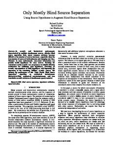
Fig. 1. Schematic diagram of the proposed coupled microphoneaccelerometer sensor pair for MMG signal recording. A representation of the mechanical effect produced by the silicone membrane vibration in the microphone’s air chamber is included. An ideal linear spring model may be assumed.
Manuscript received April 14, 2004; revised January 30, 2005. This work was supported in part by the Bloorview MacMillan Children’s Foundation, in part by the Natural Sciences Engineering Research Council of Canada, and in part by the Hospital for Sick Children Foundation. Asterisk indicates corresponding author. *J. Silva is with the Rehabilitation Engineering Department, Bloorview MacMillan Children’s Centre, 150 Kilgour Road, Toronto, ON M4G 1R8, Canada. T. Chau is with the Rehabilitation Engineering Department, Bloorview MacMillan Children’s Centre, Toronto, ON M4G 1R8, Canada. Digital Object Identifier 10.1109/TBME.2005.851531
Fig. 1 shows a schematic diagram of the mentioned vibration sensor. The sensor consists of two transducers (i.e., a microphone and an accelerometer) soldered back to back on a printed circuit board. The device is embedded into a silicone case enclosing a sealed air chamber at the microphone’s side that converts vibration signals into acoustic pressure. The sensor is designed to detect two different signal sources, namely, muscle vibration and external forces. As stated in [3], the sensor can be fastened directly over the skin on the microphone side. In this way, skin vibrations drive the sensor’s silicone membrane which, in turn, modulates the acoustic pressure measured by the microphone inside the air chamber. Forces acting externally, such as the inertia produced by body movements, push the sensor against the skin causing undesirable pressure changes (i.e., signal interference). On the other hand, skin vibrations are dampened by the silicone membrane and the air chamber before they reach the accelerometer. In other words, there is a considerable mechanical impedance mismatch between the accelerometer and skin vibration signals, such that only movement caused by external forces can be directly measured by the accelerometer. Therefore, the complementary information provided by the two transducers in the coupled vibration sensor pair can be used to discriminate among potential sources and eventually, to dynamically eliminate the un-
I. INTRODUCTION ECENT advances in muscle activity monitoring based on the mechanical effects of contracting muscles [i.e., Mechanomyography (MMG)] and the aplication of multisensor technology have lead to the development of a small-size (1.9 1.9 1.0 cm in width, heigth and length, respectively) coupled microphone-accelerometer sensor pair for dynamic noise reduction in practical physiological acoustic signal recording [1]–[4]. Although the coupled sensor has been specially designed and optimized for muscle activity monitoring within soft silicone sockets for externally powered prostheses, it can also be used to detect muscle fatigue and other low frequency physio-mechanical signals such as aspiration signatures during swallowing [5], [6], where the contamination of an acoustic signal by ambient vibration confounds detection but cannot be easily removed (i.e., similar power density spectrum and random phases for both signal and noise).
0018-9294/$20.00 © 2005 IEEE
1494
IEEE TRANSACTIONS ON BIOMEDICAL ENGINEERING, VOL. 52, NO. 9, SEPTEMBER 2005
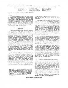
Fig. 2. Sample MMG signal from wrist extensors (left) and external interference caused by limb movement (right). Signals were recorded using the coupled microphone-accelerometer sensor pair in Fig. 1. The top traces correspond to the rectified microphone signals. The rectified accelerometer signals are plotted at the bottom. Reprinted with permission © IEE 2003 [3].
wanted interference. Fig. 2 shows sample recordings with the coupled microphone-accelerometer sensor pair, demonstrating the aforementioned mechanical impedance mismatch. A MMG signal from wrist flexors is shown on the left and external interference caused by limb movement on the right. The top traces correspond to the rectified microphone signals and the bottom traces correspond to the rectified accelerometer signals for each example. Note that without the complementary information provided by the accelerometer, noise discrimination whitin the microphone signal would be practically impossible [3]. A. Rationale: Model-Based Source Separation Based on the information above, two interfering sources in the microphone signal may be identified when using the proposed coupled sensor pair for MMG signal recording: 1) the useful skin vibration due to muscle contraction, and 2) unpredictable external forces produced by limb movement, limb vibration or sudden tapping, all of which induce relative movement of the silicone membrane with respect to the sensor case, causing an undesirable pressure change in the microphone’s air chamber [3]. It has already been established that the information obtained from the transducers (microphone and accelerometer) signals within a single sensor pair differs significantly for each of these sources. For instance, it can be readily noticed that the accelerometer is only capable of detecting the external undesirable forces [3]. However, nothing yet has been said about the nature of this detection by the accelerometer or the relationship between the sources and the microphone signal. If the exact mathematical relationship or an adequate approximation thereof between the interfering sources and the signals acquired from the coupled MMG sensor pair are known, transfer functions from the aforementioned sources (inputs) to the sensor signals (outputs) may be obtained. If validated, this model will automatically use the magnitude and phase information simultaneously to provide the best possible estimate of the outputs.
Furthermore, if a linear time-invariant (LTI) system is assumed, the inversion of these transfer functions will reveal the electronic circuit implementation that provides the most efficient and reliable real-time source separation strategy. Other source characteristics that support this model-based approach are: 1) The power spectra of both sources (i.e., MMG and limb movement) overlap in the bandwidth of interest (5–50Hz). Therefore, no simple filtering techniques can be applied to track skin vibrations under these conditions. 2) The onset of muscle contraction (source activation) and external forces is by nature unpredictable (random phase), therefore, the phase information of the acquired signals will not be useful for source separation unless the relative phase shift observed among sensors can be compared to the real phase shift, if any. A mechanical model based on the physical interactions of the sensor components will provide the best estimate for such a phase shift. It is important to note however, that the performance of the proposed model-based source separation will be extemely dependent on the reliability of the model itself. Therefore, if such an approach is taken, special attention must be paid to the validation and precise justification of the parameters involved. The ensuing sections present the proposed model for the coupled microphone-accelerometer MMG sensor pair, together with its validation and optimization. The main objective of developing a model is the generation of a reliable source separation algorithm based on the fusion of data from individual transducers within a single sensor pair. II. THE MODEL Based on the assumption of a linear time-invariant (LTI) system, a one-dimensional model for the coupled MMG sensor pair is proposed. This model accounts for the dynamic interactions of the mechanical variables involved in practical MMG signal recording. Three-dimensional and radial effects of the and external measured sources (i.e., muscle displacement ) are dismissed on the assumption that sensor design force maximizes sensitivity in a single axis (i.e., perpendicular to the sensor’s silicone contact membrane). Furthermore, the small bump at the bottom of the silicone membrane restricts the location of the skin vibration source to the center of the air chamber. Therefore, point source localization is also assumed. A. Air Chamber Mechanics Fig. 1 shows a graphical representation of the mechanical variables involved in the determination of the mathematical of the sensor silicone relationship between a displacement inside the air membrane and the acoustic pressure chamber as measured by the microphone. If the air chamber can be seen as case is assumed stiff, the displacement a varying position source which changes the height of the cone-shaped membrane surface generated during vibration. If as the membrane position at which the we consider pressure of the air chamber equals the atmospheric pressure (i.e., when the silicone membrane is flat), positive and negative will then correspondingly cause compresdisplacements sion and rarefaction of the microphone’s air chamber. In this
SILVA AND CHAU: MATHEMATICAL MODEL FOR SOURCE SEPARATION OF MMG SIGNALS
1495
sense, for every given position value there is a correinside the air chamber. sponding constant pressure value This pressure, together with the elasticity of the membrane (as a tendency to recover its original form), cause a spring effect at the center which acts locally exerting a restoring force of the membrane and opposite to the vibration source, that is (1) where is the restoring force due to the air chamber comis the restoring force due to the pression/rarefaction and silicone membrane elasticity. due to air compression/rarThe magnitude of the force efraction is given by the relationship (2) where is the membrane surface area and is the pressure change (acoustic pressure) inside the air chamber with [7]. The area respect to the equilibrum position and pressure change are functions of the given . The cone-shaped membrane surface position value, area for any given value is approximately (3) where is the air chamber radius . The change in pressure can be calculated from Boyle’s law which for an isothermal compression gives (4) (5) (6) (7) where and are the respective pressure and volume values at equilibrum , is the air chamber volume for , is any given relative membrane position the cone-shaped volume formed by the vertical displacement at the center of the silicone membrane, and is the air chamber height . Finally, substituting (3) and (7) into (2), becomes the magnitude of the reaction force (8) Aditionally, as mentioned before, the elasticity of the silicone membrane will also contribute to the spring effect. The restoring radial tension exerted on the cone-shaped membrane surface can be easily calculated if the Young’s modulus of the silicone is known. However, only the vertical component (i.e., in the direc) of this tension should be considtion of the displacement ered since the horizontal component will be opposed by the stiff walls of the air chamber along the whole perimeter. The reacthen becomes tion force due to membrane deformation (9) where and Young’s modulus
are the thickness
and of the silicone mem-
Fig. 3. Reaction forces due to membrane displacement calculated for the air chamber (F ) and silicone membrane (F ). The total force F is also shown for comparison.
brane, respectively. Fig. 3 depicts the forces caused by air compression/rarefaction, and by the silicone membrane tension ( and , respectively) as functions of relative membrane posicalculated using (8) and (9). This graph shows that tion the effect of the membrane on the total restoring force (bold trace) is minimum and only considerable as the displacement approaches extreme values . This demonstrates that we can still obtain a good approximation to the total by only considering the restoring force reaction force due to air chamber compression/rarefaction. Furthermore, will ever acquire values lower than 0 mm it is unlikely that since the small bump at the bottom of the silicone membrane will prevent negative acoustic pressures inside the air chamber. Therefore, in spite of the nonlinearity of the total reaction , a local linearization is possible in the range of inforce terest. If the height of the bump is approximately 0.5 mm, it is then possible to choose 0–1 mm as the range of interest for the values will fall. Using linearization in which most of the least squares linear regression, the ideal linear function for the modeled spring becomes (10) where is which now has the form the spring constant of the linear “spring of air” described above. The small offset produced by the linearization can be seen as an additional constant force applied to the “spring of air.” However, it can be discarded from the model since any constant (static) force that does not cause limb movement will be equally opposed by the elasticity of the silicone sleeve and no effect will be detected with any of the transducers in the MMG sensor. If an electrical equivalent is considered, the inductance will represent the behavior of the ideal linear spring which couples every vibration to the acoustic pressure measured by the microphone. Three significant assumptions have been made for this section of the model: 1) an ideal linear spring ; 2) an isothermal compression of the behavior air chamber; and 3) a massless system. The assumption of an isothermal compression was computationally validated. No sigwere found when restoring forces nificant differences for isothermal and adiabatic compressions of the sensor’s air
1496
IEEE TRANSACTIONS ON BIOMEDICAL ENGINEERING, VOL. 52, NO. 9, SEPTEMBER 2005
$
$
Fig. 4. Electromechanical model of the coupled MMG sensor pair in Fig. 1. Corresponding equivalents are as follows: force current, velocity voltage, mass capacitance, stiffness inductance and mechanical damping resistance.
$
$
$
chamber were calculated. On the other hand, the restoring force of the proposed “spring of air” will rapidly exceed the inertia caused by the minute masses of the air column and silicone membrane, thereby validating the third assumption. B. Model Integration Fig. 4 depicts an electromechanical equivalent 1, of Fig. 1 showing the remaining mechanical variables involved in practical MMG signal recording when using the proposed coupled MMG sensor pair embedded within a soft silicone socket as a holding mechanism. A variable velocity/voltage represents the skin vibration due to muscle source contraction. This source is coupled to the “spring of air” with and the unknown mechanical damper spring constant which prevents sustained system oscillation. This spring and which damper are in turn connected to a mass differential represents the section of the soft silicone sleeve containing the coupled MMG sensor. This mass is then connected to the by means of the silicone sleeve, whose elasticity is forearm represented by a second presumably linear spring with spring coupled to its corresponding mechanical damper constant . It is easy to note that the stiffness coefficient will be considerably higher than since the sleeve is stiffer than the air chamber (any force applied directly to the sensor will considerably deform the air chamber before any local deformation in the sleeve may be noticed). However, recall that any relative can be caused displacement of the silicone membrane or by interfering forces either by skin displacements acting externally on the coupled MMG sensor pair. This means that the coupling between the sensor and the forearm is not completely stiff and some of the energy from external forces is still being transmited to the air chamber. Therefore, although it of the sleeve cannot be may tend to infinity, the stiffness discarded. 1For a detailed explanation of the methods used for the determination of electrical equivalents, refer to [8] and [9]
Fig. 5. Electrical equivalent circuit (a) and impedance circuit (b) of the model proposed in Fig. 4.
Fig. 5(a) shows an electrical equivalent of the model proposed in Fig. 4. A variable current source substitutes the external force . Fig. 5(b) shows the corresponding impedance cirvector cuit. Voltages at specific branches of the circuit now represent the transducers’ signals within the coupled MMG sensor. These for the microphone and for the acceleromvoltages, eter, represent the membrane relative velocity (with respect to sensor velocity) and sensor velocity, respectively. Note that the physical transducer measurements are related to these voltages as follows: (11) (12) where is the relative membrane position with respect to the sensor case and is the sensor acceleration. An additional in order nonlinear transformation (13) must be applied to to obtain the value of acoustic pressure measured by the microphone. From (7) and (11) (13) Finally, the circuit in Fig. 5(b) can be solved by obtaining functions for the outputs ( and ) as functions of the and ). In terms of impedance (i.e., their sources ( Laplace transform) these functions are (14)
(15)
SILVA AND CHAU: MATHEMATICAL MODEL FOR SOURCE SEPARATION OF MMG SIGNALS
1497
where (16) (17) (18) (19) Furthermore, inverse functions may be obtained by solving the system of (14) and (15) for the sources ( and ) and by substituting the corresponding variables from (11) and (12). In terms of impedance these functions are
(20)
(21) where and can be calculated from the microphone and accelerometer signals, respectively, as (22)
Fig. 6. Schematic representation of the experimental setup for model validation measurements.
of consequently changes the model response. However, no decrease in model performance is expected for real MMG signal recording assuming that the proposed experimental setup sufficiently characterizes the real conditions. and 3) The stiffness coefficient for the silicone sleeve and are the value of the mechanical dampers initially unknown. However, some constraints for the possible values of this variables can be derived and used for model optimization. 4) The presented model considers exclusively the transduction of mechanical signals measured by the coupled MMG sensor. Aditional electronic circuitry such as filters and amplifiers conected to the transducers will modify these responses. Therefore, a preprocessing stage which eliminates any effects from such electronic circuitry must be added prior to the use of the model.
(23) III. MATERIALS AND METHODS where and are the signals from the microphone and accelerometer, respectively, within a single coupled MMG and are the corresponding sensitivity sensor pair, and values for each transducer. Equation (20) is then a model-based data fusion algorithm, which uses the signals acquired from individual transducers within a single coupled microphone-accelerometer MMG sensor pair to track the vibrating source (i.e., ) due to muscle contraction. This algorithm skin vibration may be implemented using analog electronics and will dynamically eliminate any interference in the microphone signal caused by external forces on the MMG sensor. Important assumptions and considerations for the presented model are: 1) The measured value for the coupled MMG sensor’s mass was 5 g. This parameter represents only a discrete approximation of the sleeve’s mass differential which contains the sensor. However, due to the significantly higher mass of the sleeve and the forearm, the assumption of a discrete mass differential should not affect the results considerably. must be individually measured for 2) The forearm mass every user and must include the mass of the residual limb, the sleeve and the prosthesis. However, for model validation and optimization (see Section III), only the masses of a mechanical stimulator and the silicone square section which contained the MMG sensor, i.e., a simulated . The adjustment forearm, were considered
A. Model Validation In order to validate the proposed model, a controlled experiment involving real measurements with the coupled MMG sensor was performed. Fig. 6 shows the experimental setup. A coupled MMG sensor pair embedded in a silicone square section (305 mm 305 mm) was fastened to a custom-made mechanical stimulator built with a flat type speaker2 mounted in a resonance box [1]. This mechanical stimulator was used to simulate the useful vibrating source (i.e., skin displacement ) due to muscle contraction. In order to facilitate suspension, the silicone soft socket must fit tightly on the patient’s stump. This causes an initial tissue compression and increase of the apparent stiffness of the silicone sleeve. Additional tissue compression may occur during practical MMG recording. Further, some of the energy produced by external forces applied on the coupled MMG sensor may be absorbed by the tissues as opposed to the microphone’s air chamber. In order to recreate this possible soft tissue compression, and therefore, external force attenuation during MMG signal recording, a 2 mm silicone gel layer3 was placed between the sensor and the mechanical stimulator. This gel possesses similar mechanical properties as soft tissue and tissue simulants previously used in tissue mechanics research [10], [11]. The stimulator, together 2Panasonic 3GEL-8150
model WM-R57A from NuSil Technology
1498
IEEE TRANSACTIONS ON BIOMEDICAL ENGINEERING, VOL. 52, NO. 9, SEPTEMBER 2005
with the MMG sensor and silicone gel layer, were then secured on a shaker platform.4 Note that the inertia caused by the vibration of the shaker can be seen as a controlled force acting externally (opposite to the direction of vibration) on the MMG sensor. Therefore, limb movement, which causes significant interference in the microphone signal, can be simulated. An accelerometer model BU-7135 from EmKay Innovative Products, was used to measure the acceleration of the shaker platform. These measurements can then be used to approximate acting externally on the value of the force of inertia the MMG sensor. The setup presented in Fig. 6 provides us with an environment similar to the real MMG signal recording conditions in which the parameters of the skin vibration source and the external force source can be controlled. Furthermore, tests in which both interfering sources are simultaneously active as well as single frequency measurements may also be performed and compared to the model. Three sets of measurements for frequencies ranging from 5 to 100 Hz were performed with increasing values of sinusoidal forces applied by the shaker on the mechanical stimulator (and, therefore, the MMG sensor). The root mean square (RMS) magnitude of the corresponding sinusoidal accelerations caused by these forces on the shaker platform were approximately 1.76, 6.96 and 13.83 ). Signals from each transducer within the coupled MMG sensor pair and the accelerometer on the shaker platform were acquired simultaneously at a sampling rate of 1 kHz during an average time window 0.5 s in length. These signals were stored for further analysis. B. Model Optimization The frequency response of each transducer in the coupled MMG sensor pair due to excitation from the mechanical stimulator will not be as reliable as that due to shaker excitation. This is because the vibration of the flat-type speaker in the mechanical stimulator cannot be directly measured and may be biased by its own frequency response. Furthermore the accelerometer does not present significant sensitivity to skin vibrations. Thus, to provide reliable validation of the proposed model, only frequency response measurements of signals acquired from the shaker were used for model optimization. These empirical responses represent two thirds of the available information for model optimization. It is conceivable that the optimal parameter values may depend on whether the full set or chosen subset of frequency responses are considered. However, the chosen subset of frequency responses completely characterize the undesired external force, suggesting that additional information may be redundant and unlikely to significantly change the optimal parameter values. The empirical responses were compared to the responses obtained from the model. In this case, the measured is considered the input to the system and external force signals acquired with each transducer within the coupled MMG sensor are the outputs. A program was written in the MATLAB environment to calculate the corresponding frequency responses of the microphone and accelerometer within the coupled MMG sensor 4T2000
ration
Series Electrodynamic Shaker System from Unholtz Dickie Corpo-
due to an externally applied oscillatory force . This program segmented every recording (i.e., shaker acceleration, microphone signal, and accelerometer signal) into individual segments of one period in length. The RMS value, period and signal delay with respect to the source for each cycle were calculated. Finally, the mean RMS, frequency and phase over all the cycles in the recording window were obtained. These values were then used to determine the empirical frequency responses of the microphone and accelerometer due to shaker vibration. In order to obtain a better representation of the empirical data, polynomial functions were fitted to the empirical magnitude and phase response data for each system. These functions were then compared to the model responses using a mean square error (MSE) criterion. A multiple criteria objective function was defined to optimize the model parameters. First, consider the following single criterion objective function: (24) is the model’s where is a vector of model parameters, is the corresponding empirmagnitude or phase response, ical magnitude or phase response, and is a single frequency value. To maximize the fit between empirical and model responses, four single criterion functions, each in the form of (24) were formulated. In particular, there were two objective and , for optimizing the functions. transfer function from the shaker to the microphone. Likewise, and were two objective functions, associated with optimizing the shaker to accelerometer transfer , function. The overall multiple criteria objective function, was then formulated as the sum of the individual objective functions (25) This multiple criteria function represents the total MSE between empirical and model responses. As mentioned earlier, the stiffness coefficient for the silicone should be higher than that of the air chamber . sleeve This represents a parameter constraint. In addition, none of the parameters can take negative values since they are all based on real mechanical components. The optimization problem can such that now be formulated as to minimize (26) (27) where and is defined as in (25). Optimization was performed using the Nelder-Mead algorithm [12] in the MATLAB environment and provided a set of values , which resulted in the best possible fit with the empirical data. IV. RESULTS Figs. 7 and 8 show the empirical magnitude and phase responses of microphone and accelerometer, respectively, to the . Polynomial regressions for each graph are external force
SILVA AND CHAU: MATHEMATICAL MODEL FOR SOURCE SEPARATION OF MMG SIGNALS
1499
Fig. 9. Empirical (solid line) and optimum model (dashed line) responses for the transfer functions involved in the model optimization.
Fig. 7. Empirical magnitude and phase responses of microphone to an external force F (t). Each point is calculated from the estimated force applied by the shaker platform F (t) to the measured relative membrane position l(t) in the coupled MMG sensor. The corresponding fitted polynomials are also shown as the solid lines.
Note that the slope related to a time delay ship
in each of the phase responses can be of the output signals by the relation-
(28) Therefore, the real phase response can be approximated as a constant equal to the offset of each linear regression for the phase response (i.e., and 2.1128 for the relative membrane displacement and sensor acceleration, respectively). This approximation simplifies the model optimization since the exact contribution of the modeled sensor components to this delay is difficult to track. In other words, the time delay may not have been exclusively caused by the components in the coupled vibration sensor (e.g., additional electronic circuitry in the data acquisition system could also have significantly contributed to this delay). therefore, the model-predicted phase responses may present some degree of variability around the empirical offset values. Finally, by minimizing the total MSE between the empirical and modeled responses, the optimal values of , and 1/1.6170 were ob, and , respectively. Fig. 9 tained for the parameters compares the empirical and optimum model responses for each of the transfer functions involved. Note that the vertical scales have been magnified to highlight differences between the empirical and model-predicted responses. V. DISCUSSION
Fig. 8. Empirical magnitude and phase responses of accelerometer to an external force F (t). Each point is calculated from the estimated force applied by the shaker platform F (t) to the measured sensor acceleration A(t) in the coupled MMG sensor. The corresponding fitted polynomials are also shown as the solid lines.
superimposed. As mentioned earlier, these regressions were used during model optimization as representations of the corresponding empirical frequency responses measured for each sensor.
From the results reported in Fig. 9, we observe only a 2-dB maximum error in the optimized magnitude response of the . Likewise, the maximum error relative membrane position for the sensor acceleration magnitude response was only 1 dB. Maximum values of phase errors were 20 or 11% of 180 (i.e., , and 2 or half a period) for the membrane displacement 1.1% of 180 for the sensor acceleration, . These phase errors are of the same order of magnitude as the offsets in the real phase responses, therefore validating the model predicted differences.
1500
IEEE TRANSACTIONS ON BIOMEDICAL ENGINEERING, VOL. 52, NO. 9, SEPTEMBER 2005
4) Substitute values into the model and solve for the required responses. will typically be As in the MMG example, the value of considerably higher than . Note that changes in the value of and would have a considerable effect on the system’s and response. In the MMG example reported in this paper are related to the mechanical properties of the silicone sleeve which holds the sensor in place. It is important to note some of the limiting assumptions of this model. In particular, assuming a single vibration axis will not be accurate when there is relative movement between the sensor and the skin (the resultant friction will cause angular displacements due to the elasticity of the membrane). Therefore, every effort must be made to keep the sensor from moving with respect to the vibration source. An alternative solution would be to monitor vibrations on multiple axes, requiring a more sophisticated model than the presented here. VI. CONCLUSION Fig. 10. Sample source localization test for simultaneous active sources. M (t) and A (t) are the microphone and accelerometer signals in Volts and l (t) and l (t) are the measured and estimated skin vibration signals, respectively.
Hence, these small errors between empirical and model responses validate the proposed model. External variables such as errors in the precision of the electronic components likely contributed to these small differences. Once the model has been optimized, measurements in which both sources (i.e., shaker platform and mechanical stimulator) are simultaneously active can be performed. These measurements can be processed using (20) to track the original useful vidue to muscle conbration source (i.e., skin displacement traction). Fig. 10 depicts a sample model-based source separation test performed with the Simulink toolbox in the MATLAB and accelerometer environment. The real microphone recordings are shown as the top two graphs, respectively. A sinusoidal external force with an amplitude of 1.7 N and frequency of 24 Hz (second graph) was simultaneously applied with a sinusoidal skin vibration at 15 Hz and estimated (top graph). The tracked source amplitude of 3 and its estimate are shown as the bottom two graphs, respectively. The observed phase differences are mainly due to additional filtering applied to the estimated skin vibration to eliminate the position offset. Note the complete elimination of the , interfering external force in the estimated source signal in the bottom graph. Furthermore, the proposed model can be transferred to other applications following the procedure outlined below. 1) Measure the mass of the free vibrating body. 2) If the sensor is embedded, use the same approximation for as proposed in this paper the sensor mass differential (i.e., 5 grams). If the sensor is not embedded, then simply weigh the sensor. and energy dissipation 3) Obtain the values of elasticity of the material used to hold the sensors in place from data sheets or other conventional methods.
A model-based data-fusion algorithm for the discrimination of external forces in practical MMG signal recording has been proposed. This model provides the most direct real-time source separation technique for the detection of skin vibrations. The successful dynamic source separation provided by the model presented may facilitate the generation of multiple control outputs for prosthesis control. Furthermore, the methodology of model development and validation is general enough to be specialized to other applications where the continuous monitoring of physiological vibration signals highly contaminated by noise is of interest. One example is the monitoring of swallowing sounds for the detection of dysphagia in people with severe motor impairments. This is a particularly challenging task that requires the elimination of continuous and unpredictable interfering sources such as sudden movements caused by coughing, voice and respiration. REFERENCES [1] J. Silva, T. Chau, S. Naumann, and W. Heim, “Systematic characterization of silicon-embedded accelerometers for mechanomyography,” Med. Biol. Eng. Comput., vol. 41, no. 3, pp. 290–295, 2003. [2] J. Silva, T. Chau, S. Naumann, W. Heim, and A. Goldenberg, “Optimization of the signal-to-noise ratio of silicon embedded microphones for mechanomyography,” in Proc. Canadian Conf. Electrical and Computer Engineering, vol. 3, May 2003, pp. 1493–1496. [3] J. Silva and T. Chau, “Coupled microphone-accelerometer sensor pair for dynamic noise reduction in MMG signal recording,” Electron. Lett., vol. 39, no. 21, pp. 1496–1498, 2003. [4] J. Silva, T. Chau, and A. Goldenberg, “Mmg-based multisensor data fusion for prosthesis control,” in Proc. 25th Annu. Int. Conf. EMBS, Sep. 2003, pp. 2909–2912. [5] M. Boiron, P. Rouleau, and E. Metman, “Exploration of pharyngeal swallowing by audiosignal recording,” Dysphagia, vol. 12, no. 2, pp. 86–92, 1997. [6] R. Sandler, H. Mansy, V. Kumar, and K. Cline, “Computerized analysis of swallowing sounds (cass) in normal subjects,” Gastroenterology, 1997. [7] A. French, Vibrations and Waves . New York: Norton & Company, Inc, 1971. [8] J. D’Azzo and C. Houpis, Linear Control System Analysis and Design . New York: Mc-Graw Hill, 1995. [9] A. Oppenheim, Signals & Systems . Upper Saddle River, NJ: PrenticeHall, 1997.
SILVA AND CHAU: MATHEMATICAL MODEL FOR SOURCE SEPARATION OF MMG SIGNALS
[10] A. Kerdok, S. Cotin, M. Ottensmeyer, A. Galea, R. Howe, and S. Dawson, “Truth cube: Establishing physical standards for real time soft tissue simulation,” in Proc. Int. Workshop on Deformable Modeling and Soft Tissue Simulation, , Germany, Nov. 2001. [11] D. Kalanovic, M. Ottensmeyer, J. Gross, G. Buess, and S. Dawson, “Independent testing of soft tissue visco-elasticity using indentation and rotary shear deformations,” in Proc. 11th Annu. Medicine Meets Virtual Reality Conf., Jan. 2003, pp. 137–143. [12] J. Nelder and R. Mead, “A simplex method for function minimization,” Comput. J., vol. 7, pp. 308–313, 1965.
Jorge Silva (S’01) received the B.A.Sc. degree in biomedical engineering from the Universidad Iberoamericana, Mexico City, Mexico, and the M.A.Sc. degree from the University of Toronto, Toronto ON, Canada in 2002 and 2004, respectively. He is currently working towards the Ph.D. degree in the Institute of Biomaterials and Biomedical Engineering, University of Toronto He is a Strategic Training Fellow in Health Care, Technology and Place for the Canadian Institutes of Health Research. He joined the Bloorview MacMillan Children’s Centre as a graduate student in 2002 and has been working since in the development of intelligent systems for paediatric rehabilitation. His current research focuses on the development of technologies that facilitate play for children with disabilities.
1501
Tom Chau (S’93–M’98–SM’03) received the B.A.Sc. degree in engineering science and the M.A.Sc. degree in electrical engineering, from the University of Toronto, Toronto, ON, Canada, in 1992 and 1994, respectively. He received the Ph.D. degree in systems design engineering from the University of Waterloo, Waterloo, ON, Canada, in 1997. He is Canada Research Chair in Pediatric Rehabilitation Engineering, Scientist in the Bloorview Research Institute, and Assistant Professor at the Institute of Biomaterials and Biomedical Engineering, University of Toronto. After working for IBM, he joined the research staff at Bloorview MacMillan Children’s Centre in mid-1999 and was appointed a research chair in 2004. His research program focuses on finding practical technological solutions to enable children with disabilities to achieve their personal best.