ISTANBUL UNIVERSITY – JOURNAL OF ELECTRICAL & ELECTRONICS ENGINEERING
YEAR VOLUME NUMBER
: 2009 :9 :1
(853-860)
A MICROCONTROLLER BASED GENERATOR DESIGN FOR ULTRASONIC CLEANING MACHINES Mehmet YAKUT
Ali TANGEL
Cemile TANGEL
Kocaeli University, Dept. of Electronics and Communication Engineering, Izmit/Turkey
[email protected]
ABSTRACT In this study, driver and power units of a microcontroller based ultrasonic generator, which has advanced controlling functions are designed and implemented for 28 KHz ultrasonic cleaning machines. The importance and usage of ultrasonic frequencies for surface cleaning purposes are addressed. The designed generator has the ability of automatic frequency control as a solution to the problems of degradation on power and cleaning efficiencies results from the resonant frequency deviations of ultrasonic transducers due to load changes on cleaning tanks. For this purpose, a special software algorithm is developed. Since its operation has the property of frequency sweeping in a narrow frequency band, more homogenous cleaning patterns have been observed after the foil tests, and the related results are included in this article. Moreover, temperature and timing controls, and also protections against possible short circuits in the power unit are among the additional properties of the designed generator. It can easily be adapted to the multi-frequency ultrasonic cleaning systems by additional commands into the software running on the microcontroller.
Keywods: Ultrasonic cleaning, microcontrollers, ultrasonic generators.
1. INTRODUCTION Ultrasound is the sound waves transmitted at frequencies beyond the range of human hearing. The main principle of using ultrasonic for cleaning purpose is explained as follows: Millions of bubbles formed by ultrasonic waves inside a liquid contain vacuum energy, called cavitation energy, strike and explode on surfaces of the objects which are put inside the liquid. After the explosion, about 5000 °C of temperature effect takes place surroundings of the bubbles. These collision and temperature Received Date: 30.10.2007 Accepted Date:05.01.2009
effects collide with the objects inside the liquid. Therefore, unwanted layers such as oils and dirts are fastly removed from the surfaces of the objects to be cleaned [1], [2]. During the cavitation, how much the bubble sizes will grove inside the liquid depends on the amplitude and the frequency of the signal applied to the ultrasonic transducer. The cleaning power can be increased until the unwanted effect, so called “cavitation erosion” occurs. The cleaning efficiency decreases if the applied power is increased further.
854 All liquids contain dissolved oxygen inside [3]. For an ultrasonic cleaner to work properly, this dissolved oxygen and some other gases must be removed from the cleaning solution. This process is known as degassing. In other words, useful cavitation occurs after gasses have been removed from the solution. The cleaning power of a cleaning tank depends on how strong the bubbles collapse. Existence of any gases inside the solution reduces the pressure of that region, which finally prevents the strong collapsing of the bubbles. Pulsing is most commonly done by means of a pulsing cicuit provided integrally in the body of high quality ultrasonic generators. Therefore, microprocessor based generator implementations are widely preferred for the designers [4]. In this study, such an ultrasonic generator system, which has a novel software algorithm and a power-driver circuit, has been designed, implemented, and tested. There are ultrasonic systems starting from 20 kHz to 2MegHz [5]. Selection of the frequency range depends on the types and the amount of desired cleaning. For instance, 20-40KHz systems are used for cleaning heavy motor blocks and metals. 40-70 KHz systems are used for cleaning delicate parts, optics, and in medical or dental laboratories, and jeweler sector. Over 70 KHz frequencies are used for cleaning very small particles and substances in electronics and semiconductor technology [3]. Nowadays, modern ultrasonic cleaning systems uses multifrequencies assembled on the same tank. Cleaning tank must be made of stainless steel and it must be as thin as possible. Ultrasonic transducers are located on the bottom of the tank by using a special glue. The number of transducers to be placed and the distance between them depend on the size of the tank. There are also so called “immersible transducers” on the market. They are located inside the cleaning liquid by using a waterresistant metal box, in which transducers are mounted. The objects to be cleaned are never placed directly to the bottom of the tank. Instead, they are put inside the tank by using a special cageshaped basket which is made of a stainless steel as well. The distance between surface of the
liquid and the top of the basket should be about 2-3 cm. Although di-ionized water is usually preferred as a cleaning liquid, chemical solutions and detergents are also used depending on application.
2. DESIGN AND IMPLEMENTATION OF THE MICROCONTROLLER BASED ULTRASONIC CLEANING MACHINE Block diagram of the designed and implemented ultrasonic generator is depicted in Figure 1. Here, the developed software algorithm to be run on the microcontroller circuit has the following features: 1. Ability to set the operating frequency manually in the range of 20 KHz-40KHz, if necessary. 2. Cleaning-power control by PWM pulses. 3. Timing control for proper degassing. 4. Automatic power shut-down property in case of overflow for limit temperature value on power MOSFETS used in the power unit. 5. Automatic power shut-down for the heaters located on the outer sides of cleaning tank in case of overflow on instantaneous temperature value set for the cleaning liquid. 6. Display controls to indicate temperature, operating modes, power adjustment, frequency adjustment, and operation time. 7. A special algorithm to recover the resonant frequency of ultrasonic transducers due to possible deviations on their resonant frequencies resulted from changes on tank loadings. An analogue feedback circuitry is used for this purpose in addition to the power unit. The required supply voltages for the digital part and power units are provided by the rectifying and DC power supply unit. Power unit needs a full-wave rectified main voltage (220VRMS) to be able to drive ultrasonic transducers. This high DC voltage is modulated by the ultrasonic PWM pulses produced by the microcontroller unit. Isolation unit works as a driver circuit for the power MOSFET in the power unit. Because, voltage levels of PWM pulses are not high enough to be able to drive power MOSFETs’
Mehmet YAKUT, Ali TANGEL, Cemile TANGEL
855 gates. Moreover, isolation between low voltage part and high voltage part is important for safety.
finally fed back to the ADC input of the microcontroller passing through an envelope detector circuitry, which is not depicted here. A similar application of this method can be found in the literature [6]. In general, one can find examples of full-bridge inverter [4], [6], [7], and push-pull inverter [5] structures for DC-AC conversion purposes in the literature.
3. SOFTWARE ALGORITHM FLOW CHART
Figure 1. Block Diagram of the designed ultrasonic generator.
Figure 2. Schematic of the power unit.
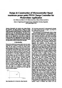
Schematic of the power unit is shown in Figure 2. Power unit produces an amplitude-modulated signal across the transducers, where envelope of the modulated signal has 100 Hz, but the carrier frequency is 28 KHz. The maximum voltage observed across the transducers is about 600Vpp. This voltage value changes between 500V and 600V during cleaning operation.
The software algorithm developed is explained by a long program flow-chart shown in Figure 3. The software has one main program and four sub-programs connected with it. It is written in CCS-C language. The first prototype generator is designed such that it has 22 different cleaning modes for testing purposes. These modes can be categorized in three groups as degassing period adjustment modes, frequency sweeping modes, and fixed frequency operation modes. In the so called “C” program stage, operation modes are selected by control buttons, and kept in the steady memory. In the main program, initial conditions are set. Initial values are dedicated to the parameters to be used. Later on interrupt arrangements are done. Finally, selection of operating mode is done. If a new mode is demanded, it is done by control buttons, and this demand is executed. Otherwise, the latest mode is read from the eeprom. This is also indicated on the display as the current active mode. One can move to the any one of the modes between 0 0
START=OFF B B
N COUNT=250
Return from interrupt service routine Y
MOD > 0
B
N PWM Timer interrupt service routine
MOD=10 N
START=ON
B
PWM Timer Interrupt
Y Update POWER, TEMP, MOS temp values
Update PERIOD
Increment PCOUNT by 1
Update POWER
N
PCOUNT=4
B
I=Read output current (ADC)
Y PCOUNT=0
SUM=SUM+I (mean current integration) N
START=ON
B Return from PWM interrupt
Y Increment SECOND by 1
Mehmet YAKUT, Ali TANGEL, Cemile TANGEL
A
857
C
MOD +?
N
Y MOD = MOD+1
MAIN Program
MOD - ?
N
Y Initialize variables from EEProm to default values
MOD=MOD-1
Clear COUNT Setup ADC
MOD OK ? Y D
Initialize Interrupts If new MOD is selected, part (C) runs Y
New MOD > ON N
C D
X= MOD H
0 >= X < 22
Last MOD: is Active MOD User selects one of the modes among 0-22, otherwise MOD (0) runs by default
Run the program MOD 0)
E Run the program MOD (X)
Mehmet YAKUT, Ali TANGEL, Cemile TANGEL
N
858 X program can take any numbers between 0- to21. That means, there are 22 different
MOD (X) Program Display X value of MOD for 2 seconds Read MOD parameters
STOP pressed ?
Y
START = OFF
N START pressed ?
Y
START = ON
N Change request ?
N
Y Set new POWER, TEMP, TSET (run time) and MOD values if between limit values, otherwise set to defaults
Figure 3. Software flow chart. Mod(X) sub-program works as follows: Mod parameters are read from eeprom such as cleaning time, tank water temperature, power and frequency. If the values given are beyond the limits, then the default values are set. Cleaning operation is started with 2 seconds delay. Meanwhile, set values are displayed (latest values stored in the eeprom). Other times, the set values during operation are displayed. START button must be pressed for sub-program to be able to start execution. It is possible to adjust temperature, operation time, power intensity, operating frequency even after the cleaning operation is started. Operation can be stopped at any time by pressing the STOP button.
cleaning scenarios available in the prototype system. These scenarios can be grouped in four categories as follows: 1) Desired power, temperature, cleaning time and frequency adjustment can be done manually by control buttons. 2) At a specific frequency defined earlier, and at a certain time intervals, the operating frequency is swept around the center frequency in a narrow frequency range to be able to obtain better homogeneous cleaning profile. At the same time, power, temperature, cleaning time controls are also possible in this group of modes.
Mehmet YAKUT, Ali TANGEL, Cemile TANGEL
859 3) Based on the maximum value of average current taken from the current sampling transformer for about 7-8 period of time, a defined frequency range is swept until the resonant frequency is captured. Once the resonance frequency criteria is reached, then the operation frequency is set to that value continuously. 4) Based on the maximum value of average current taken from the current sampling transformer for about 7-8 period of time, a defined frequency range is swept until the resonant frequency is captured. Once the resonance frequency criteria is reached, then the operation frequency is swept around the captured resonant frequency value during specified time intervals to be able to obtain better homogeneous cleaning profile.
4. TEST RESULTS AND CONCLUSIONS During tests, aluminum foil tests were done. Cleaning patterns are examined for both directions, vertically (i.e depending on the dept of the water) and horizontally for 22 different operation modes. Therefore the most efficient cleaning mode was decided. It was observed that the operation modes belong to group 4 mentioned in section 3 above have shown better cleaning patterns on foil tests. The 0.5 second frequency sweeping at 4 steps around the center resonant frequency is decided to be the best scenario among others.
On the other hand, when frequency sweeping operation result is examined from Figure 5, one can see a better cleaning profile. Since the designed system is microcontroller based, different cleaning scenarios can be applied without changing the system hardware. However, in analogue and fixed frequency ultrasonic cleaning machines, there are no such choices. Figure 6 shows the photo of experimental set up of the prototype generator. Piezzo-ceramic ultrasonic transducers can also vibrate at their harmonic frequencies. For example, if transducer assemblies which can vibrate two different frequencies are placed under a cleaning tank, both coarse and fine cleaning of operation will be possible on the same ultrasonic cleaning system. As an example, 28 KHz operation is for coarse and 48 KHz is for fine cleaning. These types of systems are called as multi-frequency cleaning systems. The proposed system in this work can easily be adapted to implement such kind of cleaning system by modifying the software only. The authors have been projecting designing a multifrequency ultrasonic cleaning machine as a future work.
Figures 4 and Figure 5 show the photo of cleaning patterns for fixed frequency and frequency sweeping cases, respectively. In case of fixed frequency mode of operation, certain locations are completely destroyed but other locations are slightly affected. That means complete cleaning will be possible as long as a long enough period of time of operation is allowed. However, cavitation erosion will take place on certain locations of the cleaned objects, which is never desired. If the operation time is shorten for safety, and then certain locations on the objects to be cleaned will not perhaps be cleaned. Therefore, obtaining a homogeneous cleaning profile is very important issue. Mehmet YAKUT, Ali TANGEL, Cemile TANGEL
860 Figure 4. Fixed frequency operation mode result (Power is at maximum, operation time is 1 minute).
[2] http://www.bluewaveinc.com/reprint.htm (07.05. 2007) [3] http://www.tmasc.com/ultrasonic_cleaning_ process.htm (10.04.2008) [4] C. Buasri, A. Jangwanitlert, “Comparison of switching strategies for an ultrasonic cleaner”, 5th International Conference on Electrical Engineering / Electronics, Computer, Telecommunications and Information Technology, ECTI-CON 2008. pp. 1005-1008. [5] L. Svilainis, G.Motiejunas, “Power amplifier fr ultrasonic transducer excitatin” ULTRAGARSAS, Nr.1 (58), pp. 30-36, 2006.
Figure 5. Frequency sweeping mode foil test result under the same conditions with fixed frequency case.
[6] J. Ishikawa, Y. Mizutani, T. Suzuki, H. Ikeda, H. Yoshida, “High-frequency drivepower and frequency control for ultrasonic transducer operating at 3 MHz”, Industry Applications Conference, 1997. 32. IAS Annual Meeting, IAS '97,Vol. 2, pp. 900-905, 1997. [7] P. Fabijanski, R. Lagoda, “Series resonant converter with sandwich-type piezoelectric ceramic transducers”, Proceedings of IEEE International Conference on Industrial Technology (ICIT '96), pp. 252-256, 1996.
Figure 6. Photo of the prototype ultrasonic generator under test.
5. ACKNOWLEDGEMENT This work has been supported by the ministry of Turkish Industrial and Commercial Affairs and Everest Elektromekanik Corporation under the contract of 126.STZ.2007-2.
6. REFERENCES [1] http://www.natclo.com/dp/ultra.html (07.05.2007) Mehmet YAKUT, Ali TANGEL, Cemile TANGEL