th
14 International Conference on AEROSPACE SCIENCES & AVIATION TECHNOLOGY, ASAT - 14 – May 24 - 26, 2011, Email:
[email protected] Military Technical College, Kobry Elkobbah, Cairo, Egypt Tel: +(202) 24025292 –24036138, Fax: +(202) 22621908
Paper: ASAT-14-211-CT
A Neural Predictive Control Scheme for Small Turbojet Engines I.M. Atia * and A.M. Bayoumy † Abstract: Artificial Neural Networks (NN) is a well-known tool among artificial intelligence techniques that are able to reproduce arbitrary nonlinear relationships existing between input and output variables. Model based Predictive Control (MPC), or simply predictive control, is a family of control schemes that uses a model from the plant as a predictor of the future plant outputs a nd he nce opt imizes t he f uture c ontrol i nputs f or t he m inimum f uture e rrors a nd minimum control energy. Among this family Generalized Predictive control (GPC) is one of the most famous. In another part of this work [5],, a neural network representation is shown to be suitable for modeling a s mall g as tur bine e ngine ( SR-30). In t he pr esent pa per, t his m odel i s us ed i n a model-based predictive c ontrol s cheme. T he r esults of t his c ontroller a re c ompared w ith a classical P roportional-Integral-Derivative ( PID) c ontroller tune d offline w ith a g enetic optimization technique. Both are tested on the SR-30 turbojet engine model. PID cont roller cann ot cope w ith m odel c hanges i n t he w hole op erating range of t he e ngine and t herefore a p redictive c ontrol s cheme i s t hen pr oposed a s a s olution t o t his pr oblem. A neural m odel i s us ed a s a pr edictor f or t he calculation of G PC pa rameters. T he nonl inear system free response is obtained by recursive future predictions while the dynamic response matrix is obtained by instantaneous linearization of the input /output relation. The results illustrate the improvements in control performance that could be achieved with a neural predicative scheme compared to that of a classical PID controller. Keywords: Small tur bojet e ngines, artificial int elligence, neural n etworks, predictive controller, PID, GPC.
Nomenclature
ARX F G Gf Kd Ki, K p, N N1 N2 NN
* †
AutoRegressive with eXternal input Vector of predicted free response system impulse response matrix Fuel flow rate (kg/s) derivative gain proportional gain, integral gain Engine revolution speed,(rpm) lower value of predicting horizon Higher value of predicting horizon Neural networks
Egyptian Armed Forces, Egypt,
[email protected] Egyptian Armed Forces, Egypt,
[email protected] 1
Paper: ASAT-14-211-CT NNGPC Nu PID T tr ts
ˆ y u w
λ
Neural network generalized predictive controller Control horizon Proportional, integral and derivative controller Sampling time Rise time Settling time Vector of predicted outputs for prediction horizon Vector of future control increments for the control horizon Vector of future references Weighting factor for control increments
Introduction
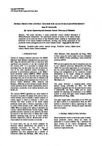
Model B ased P redictive C ontrol ( MBPC), or s imply P redictive C ontrol, i s a f amily o f algorithms with common strategy. MBPC appeared in the decade of 1970s and had got a good reputation in the chemical industries and process control [1]. The ma in strategy o f th e M BPC is as f ollows, (Error! Reference source not found.): A model of t he c ontrolled s ystem i s us ed t o pr edict i ts be haviour i n t he f uture. A know n required reference trajectory is then given for certain prediction horizon. Then an optimisation algorithm i s us ed t o find t he opt imum c ontrol s equence f or c ertain num ber of steps in the future that minimise a certain cost function which includes future predicted errors and control increments. A receding horizon technique is then applied where only the first control signal of the optimum future control sequence is applied to the controlled system.
Fig. 1 Prediction strategy Generalized Predictive Control (GPC) was developed by Clarke et al. in 1987 [2]. The GPC uses ideas from Generalized Minimum Variance (GMV) [3] and is perhaps one of the most popular methods at the moment. Since the last three decades predictive control has shown to be successful in control industry. Generalized P redictive C ontrol ( GPC) w as one of t he m ost f amous l inear pr edictive algorithms. T he control l aw of G PC c ontains t wo parameters t hat d escribe t he s ystem dynamics: s ystem f ree r esponse ( f) and system i mpulse r esponse m atrix (G). Often these parameters a re c alculated from the di screte line ar mode l. For nonl inear s ystems, either a 2
Paper: ASAT-14-211-CT nonlinear system model is instantaneously linearized or a nonlinear optimization is used. The validity of t he l inear m odel i s t he s hortcoming of t he f irst one and t he possibility of non uniqueness of local minimum is that for the second. The neural network (NN) model is used as a predictor to calculate these parameters for GPC. The nonl inear s ystem f ree r esponse i s obt ained i nstantaneously w hile d ynamic r esponse i s linearized e very b atch o f t ime. T his m ethod [ 4] i s t ested on a b enchmark nonl inear m odel. Results a re c ompared with t hat of ot her neural pr edictive t echniques f ound i n pr evious literature. Also, this method in[4] is applied and validated on a realistic multivariable aircraft model. The s imulation results s how t hat this method has s ome good advantages over ot hers neural pr edictive t echniques. In one h and, the s ystem d ynamics pa rameters ar e cal culated more accurately directly from the nonlinear NN model. And in the other hand, the used linear GPC ha s a c ost function w ith onl y on e global m inimum. T he m ethod i n [4], a s a t rade-off between nonl inear ne ural pr edictive c ontrol ( NPC) a nd i nstantaneous l inearization approximate ne ural l inear pr edictive control ( APC), i s pr omising for control of nonl inear systems. A. W atanabe e t a l [ 7] w orked on P ID and f uzzy l ogic a lgorithm i n or der t o c ontrol S R-30 turbojet e ngine. They ob tained t ransfer f unction of t he S R-30 b y using f requency response method. They tested and simulated both closed loop controller PID and fuzzy logic controller. They developed their model with MATLAB environment and tested it by NI LabVIEW. R. Andoga et al [8] discussed digital electronic control of a small turbojet engine. They stated that the main purpose of control of gas turbine was increasing its safety and efficiency. Their engine w as c ontrolled b y PIC 16 F84A m icrocontroller, which ma nipulating th e f uel f low valve. M.Lichtsinder et al. [9] worked on de velopment of a simple real-time transient performance model f or AMT j et engine. T he fast m odel i s obt ained us ing t he Novel G eneralized Describing Function, proposed for investigation of nonlinear control systems. They presented the N ovel G eneralized Describing Function de finition a nd t hen di scusses t he a pplication of this t echnique f or t he de velopment a f ast t urbine e ngine s imulation s uitable f or c ontrol a nd real-time applications. In another part of this work [5], a neural networks representation is shown to be suitable for modeling a s mall g as tu rbine e ngine ( SR-30). In t he pr esent w ork, t his model i s us ed i n a model-based pr edictive control s cheme. This mode l is line arized at di fferent en gine d esign points, this linearized model is used in design of a classical PID controller. The PID controller is t uned of fline w ith a genetic opt imization technique. B oth c ontrollers a re t ested on t he SR-30 t urbojet e ngine model a nd c omparison i s m ade be tween t he r esults f rom t hese controllers with the same input.
Turbojet Engine Controller Design
For a gas-turbine engine, particularly for a jet engine, the speed n control is one of the most important a spects ( even mos t impor tant tha n the en gine t emperature control) and it is currently realized by some specific hydro-mechanical or electro-mechanical controllers. The e ngine s peed is the mos t impor tant ope rating pa rameter, especially f or the mul ti-spool engines, because it represents the parameter which assures the most accurate co-relation with the engine thrust amount, as well as with the engine fuel consumption; meanwhile, the speed 3
Paper: ASAT-14-211-CT n offers an image about the dynamic load of the engine mobile parts (compressor blades and disks, turbine blades and disks, shafts), as well as an indirect image about the thermal charge of the engine hot parts (combustor, turbine(s), exhaust nozzle). An aircraft engine ope rates at various flight regimes, t hat m eans at various flight s peed and flight a ltitudes, which means tha t the e ngine th rust va riation must f ollow the a ircraft f light dynamics n ecessities, therefore the e ngine s peed (and thrust) mus t b e strictly c ontrolled, because of its important operating role. The engine speed is one of the engine operating parameters, which is the easiest to measure, both for s teady s tate regimes and for d ynamical regimes. That f act r epresents an advantage and promotes the engine speed as the most important controlled engine parameter. In t his pa per one ha s s tudied a n engine s peed c ontroller w ith f uel f low rate a s a r egulating parameter. The controller design was based on engine neural networks model.
Discrete PID Based on Engine NN Model
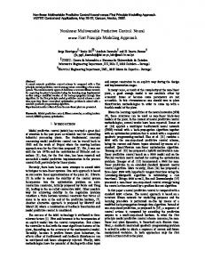
The discrete PID controller was used with the NN model of the SR-30 turbo jet engine. Now, the tuning of the PID is achieved by using genetic algorithm. The GA is carried out using a MATLAB bui lt-in r outine s o c alled S imulink R esponse O ptimization (SRO) T oolbox a s shown i n Fig. 2. T he S RO, a utomatically, formulates a n opt imization p roblem and calls a genetic algorithm and direct search toolbox, as an optimization routine to solve the problem.
Fig. 2 Simulink Response Optimization (SRO) Toolbox A classical discrete PID control system can be described as shown. The input-output relation of the PID controller is expressed mathematically by equation (1)[13]. N
u(t ) K p e(t ) TK i e(t ) Kd t 0
e(t ) e(t 1) T
(1)
where, u(t) is t he c ontrol s ignal, e(t) is t he e rror s ignal, a nd Kp, Ki, and Kd denotes t he proportional gain, integral gain and derivative gain respectively, T is the sampling time and N is the number of samples, u1(t) represents the output of the controller at the sampling point (t). If the sampling period is short enough, the approximate calculation by equation (1) can get an accurate result and the discrete control process is close to the continuous control process. 4
Paper: ASAT-14-211-CT The digital PID Controller transfer function as a function of z has the following form [13]
z K d C (z ) K p K iT z 1 T
z 1 z
(2)
where: K p, Ki and Kd are the proportional, integral and derivative parameters of the controller respectively and ‘T’ t he s ampling t ime. The r equired step response characteristics of t he engine are rise time (tr) = 0.872 s, settling time (ts) = 4 s and maximum overshoot (Mp) = 2%. PID controller i s t uned, based on t he l inearized ne ural m odel a t di fferent ope rating poi nts, with s tep c hange f rom 41050 t o 82000 r pm. The opt imal P ID p arameters a re s hown i n Table (1) and t he r esulted s tep r esponse s hown i n Error! Reference source not found. represents the engine response at step input from n= 41050rpm to n= 82000 rpm. This input covers a wide range of engine speeds. In contrast, i f t he s ame controller i s us ed w ith an i nput of s maller a mplitudes a s s hown i n Error! Reference source not found. and Error! Reference source not found., the response of the engine with the full range PID controller has a high over shoot response compared with the s cheduled P ID c ontroller. T his i s due t o t he f act t hat t he P ID controller i s a l inear controller. It i s t hus not c apable of de aling opt imally w ith a nonl inear constrained s ystem across its whole operating range. Gain-scheduling P ID co ntrollers ar e pr oposed and their pa rameters a re r ecalculated and shown in Table (1) using small-amplitude step inputs, to cover the engine operating ranges in which the data used for the estimation and validation are available. Table (1) PID parameters at different step changes based on linearized neural network models and ARX model Model
Linearized neural models at certain design points
Linearized model at no=61050 rpm
Step changes (rpm)
kp
ki
kd
MSE
41050-46050
22.3465
11.7934
2.6964
0.002554
46050-51060
9.5792
8.7627
0.99334
0.00336
51060-56050
6.1426
8.6645
1.2238
0.00371
56050-61050
6.3598
9.2752
1.1889
0.003231
61050-66060
8.3136
12.1784
0.99342
0.002649
66060-71060
5.1877
8.9899
1.6088
0.003409
71060-76100
7.479
13.4361
1.3721
0.00245
76100-82000
4.6472
10.6291
0.70902
0.002762
41050-82000
7.4465
11.5974
1.2223
0.02024
5
Paper: ASAT-14-211-CT
Fig. 3 Engine response with step change from n=41050 to n=82000 rpm. (a) Engine step response, (b) PID controller input
6
Paper: ASAT-14-211-CT
Fig. 4 Engine response with step change from n=41050 to n=46050 (a) Engine step response, (b) PID controller input
7
Paper: ASAT-14-211-CT
Fig. 5 Engine response with step change for n=71060 to n=76100 (a) Engine step response (b) PID controller input Error! Reference source not found. represents the out put f rom a n eural m odel c ontrolled with PID controller tuned at n=61050 rpm, the curve shows that the engine response became better as engine speed became near to the n o= 61050 rpm and the error increased as the point became far away from the design point no.
8
Paper: ASAT-14-211-CT
Fig. 6 Engine response with different steps change from n=61050 to n=82000 (a) Engine step response (b) PID controller input The s ystem nonl inearity is w ell illus trated if a n increasing a mplitude s quare pul se s ignal is given to the system. Error! Reference source not found. shows the response of the engine in case of square pulse signal input with the PID controller. There is an over shoot in the engine response.
9
Paper: ASAT-14-211-CT
Fig. 7 The response of the engine in case of square pulse signal input with the PID controller
Predictive controller design
In order to implement the predictive controller strategy, the basic structure shown in Error! Reference source not found. is us ed. A m odel i s us ed t o pr edict t he future pl ant out puts, based on pa st a nd c urrent va lues a nd on t he pr oposed opt imal f uture c ontrol a ctions. T hese actions are calculated by the optimizer taking into account the cost function (where the future tracking error is considered) as well as the constraints.
Fig. 8. Basic structure of MPC The basic idea of GPC is to calculate a sequence of future control signals in such a way that it minimizes a mul tistage cost f unction defined o ver a p rediction hor izon. T he i ndex t o be optimized is t he ex pectation of a qua dratic function measuring t he di stance be tween the predicted s ystem out put a nd s ome p redicted r eference s equence ov er t he hor izon pl us a quadratic f unction m easuring t he control e ffort. G PC pr ovides a n e xplicit s olution ( in t he absence of c onstraints), i t c an d eal with uns table a nd no m inimum pha se pl ants a nd incorporates t he c oncept of c ontrol ho rizon a s w ell a s t he consideration of w eighting of 10
Paper: ASAT-14-211-CT control increments in the cost function. The general set of choices available for GPC leads to a greater va riety o f control obj ectives compared t o ot her approaches, s ome of which can be considered as subsets or limiting cases of GPC. The GPC algorithm consists of applying a control sequence that minimizes a multistage cost function J: N2
Nu
2
2 J yˆ k j w k j u k j 1 j N j 1
(3)
1
Subject to: u k j 1 0 for N u j N 2 ,where N1 denotes the minimum prediction horizon, N2 the maximum prediction horizon and Nu the control horizon, λ is a w eight factor penalizing c hanges i n t he c ontrol i nput t o ob tain s mooth c ontrol i nput s ignals a nd d is the system time delay. Then the predictor equation becomes in matrix form f ˆ Gu y
(4)
where: ˆ yˆ k N 1 yˆ k N 1 1 y
T
yˆ k N 2
g 0 N1 gN1 1 g1 0 g N1 1 g1 0 G g1 gN 1 g N N 1 gN u 2 2 2 T
u k u k 1 u k N u 1 u T
f f k N 1 f k N 2
Then J could be written in matrix form as:
T u ˆ w y ˆ w u J y T
(5)
where: T
w w k N 1 w k N 2
we get: Minimize J to get optimum u
* GT G I u
1
GT w f
(6)
Taking the first element of the control sequence (as the receding horizon principle) u * k H w f where: T
H 1 0 0 0
11
G
T
G I
1
GT
(7)
Paper: ASAT-14-211-CT For a linear time-invariant system the parameter H is unchanged over the time. But the free response f should be calculated every time step. The incremental controller ensures zero offsets even with non-zero constant disturbance. The choices of p arameters ( N 1, N 2 , N u and ) de termine t he s tability and performance of t he GPC controller. Some guidelines for selecting them exist in [6-10]. Free System Response ( f ) ˆ then the To get the free system response the prescribed NN is given a zero increment vector u ˆ will be the system free response f . output predicted vector Y Impulse system response ( G ) The impulse response of the system is calculated using trained NN model with a linearization around the current operating point. To get the first column of the G matrix a small value for uˆk 1 is as sumed as s mall va lue , w here 1 and t he c orresponding out put p rediction i s obtained. ˆ 0 0 0 u (8) Then the first column will be 1 ˆ G1 (Y f)
(9)
It will be easy after that to form the special shape of G matrix then calculate H vector. Predictive controller scheme The pr oposed c ontrol s cheme Error! Reference source not found. consists of a nonl inear neural n etwork m odel i n t he f orm of N N m odel a nd a l inear G PC c ontroller. T he n eural model i s t rained of f-line w ithin the c omplete r ange o f s ystem input . After pe rforming t he training, t he n etwork i s then us ed b y the G PC controller t o calculate t he f ree r esponse of nonlinear s ystem e very time s tep. Every batch of time the impul se response ma trix is calculated through linearization. The control law Error! Reference source not found. is computed every time-step to get the next control increment.
Fig. 9 Proposed Neural Network GPC Control Scheme Application to the SR-30 NN model The predictive controller parameters are N 1 1 , N 2 4 , N u 1 , 0.05 12
Paper: ASAT-14-211-CT The s ystem nonl inearity is w ell illus trated if a n increasing am plitude s quare pul se s ignal i s given to the system. The Simulations results and Comparison with the PID controller with the same input will be illustrated below. Error! Reference source not found. shows the response of the engine in case of enhancing the f ull-step r esponse f rom 41050 t o 82000 r pm. It i s c lear t hat t he os cillation a round f inal position eliminated and the rise and settling time are reduced
Fig. 10 Engine response with step change from 41050 to 82000 rpm (a) engine step response, (b) predictive controller input Error! Reference source not found. shows the engine step response with random step input from 61050 to 46050 finally to 82000 rpm. It is clear that the engine response with predictive controller is improved where the oscillations are reduced and the settling time is reduced.
13
Paper: ASAT-14-211-CT
Fig. 11 Engine response with different steps change from n=61050 to n=82000 (a) engine step response, (b) predictive controller input The s ystem nonl inearly is w ell illus trated if a n increasing amplitude s quare pul se s ignal is given to the system. Error! Reference source not found. the response of the engine in case of square pulse signal input with the predictive controller. It is clear that there is no over shoot in the engine response.
14
Paper: ASAT-14-211-CT
Fig. 12 Engine response in case of square pulse signal input (a) engine step response, (b) predictive controller input
Results of comparison between PID controller and predictive controller
In t his s ection, a comparison i s m ade b etween t he P ID c ontrollers with t he pr edictive controller w ith r espect t o t he s ame i nput s ignal as s hown i n Error! Reference source not found., 14 and 15. 15
Paper: ASAT-14-211-CT
Fig. 13 Comparison between PID and predictive controllers in case of in case of square pulse signal input (a) engine step response, (b) controller input
16
Paper: ASAT-14-211-CT
Fig. 14 Comparison between PID and predictive controllers in case of step input from 41050 to 82000 rpm (a) engine step response, (b) controller input
17
Paper: ASAT-14-211-CT
Fig. 15 Comparison between PID and predictive controllers in case of different steps input from 61050 to 82000 rpm (a) engine step response, (b) controller input The Simulations results of the predictive controller and Comparison with the P ID controller with the same input are illustrated above which show that the engine performance is improved with t he pr edictive controller, t he r esponse os cillation a nd ove rshoot i s s maller w ith t he predictive controller rather than the PID controller, the engine rise time is also smaller. It can be t herefore con cluded that t he pa rameters i n the gain-scheduling P ID controller need t o be changed with the operating range, but using predictive controller enables a global controller to be i mplemented a nd pr ovides t he opt imal c ontrol pe rformance a cross t he ope rating r ange. Predictive c ontroller pr ovides t he be st c ontrol p erformance against di sturbances a nd m odel uncertainties.
18
Paper: ASAT-14-211-CT
Conclusion
A r epresentative n eural network SR-30 e ngine model w as us ed t o de velop a P ID c ontroller and pr edictive controller. R esults f rom t he t wo c ontrollers w ere compared a nd p redictive controller found to be accurate for engine control during the full operating rang. The following results are derived from our analysis: 1. PID controller was built based on the neural networks model of the SR-30 engine. 2. Tuning of t he P ID c ontroller w as pe rformed w ith of fline w ith a g enetic opt imization technique. 3. PID c ontroller c annot c ope w ith m odel c hanges i n t he w hole ope rating r ange of t he engine. 4. A ne ural m odel w as us ed as a pr edictor f or t he cal culation of G PC pa rameters. The nonlinear s ystem f ree r esponse w as obt ained b y r ecursive f uture pr edictions w hile t he dynamic response matrix was obtained by instantaneous linearization of the input /output relation. As a conclusion, the r esults illus trate c learly the impr ovements in system pe rformance tha t could be achi eved with a ne ural p redicative con troller com pared t o that of a classical P ID controller.
References [1] [2] [3] [4] [5] [6] [7] [8] [9] [10] [11] [12] [13]
Garcia C .E. , P rett D .M. , a nd M . M orari,“ Model predictive control: theory and practice- a survey ,” Automatica, 25(3): 335-348, (1989). D.W. Clarke, C Mohtadi, and P.S. Tuffs. “Generalized Predictive Control. Part I. The Basic Algorithm. Automatica” 23(2):137-148, 1987. D.W. C larke a nd P .J. G awthrop. “ Self-tuning Control. Proceedings” IEEE, 123: 633640,1979. A. M . B ayoumy, J . B ordeneuve-Guibé , “A Neural Predictive Control Scheme For Nonlinear Plants”, D epartment of A vionics a nd S ystems, E NSICA, T oulouse, FRANCE, AIAA 2002-1541. I. M. Atia and A. M. Bayoumy “Testing and Model Identification of a Turbojet Engine Using Neural Networks”. ASAT-14, 2011 Clarke D .W., C . M ohtadi a nd P .S. T uffs,“ Generalized Predictive Control. Part2: Extensions and interpretations,” Automatica, vol.23, Nº2, pp. 149-160, (1987) Watanabe, A ., l men, S . M., Leland, R ., W hitaker, K . W ., and T revino, L. C ., 2004, “Soft Computing Applications on SR-30 Turbojet Engine” AIAA Paper No. 2004–6444. Andoga, Rudolf, Ladislav Madarasz, and Ladislav Fozo. "Digital Electronic Control of a Small Turbojet Engine - MPM 2." 12. International Conference on Intelligent Engineering Systems. Miami, Florida. 37-40, 2008. Michael Lichtsinder, Yeshayahou Levy “Jet Engine Model for Control and Real-Time Simulations” Journal of E ngineering for G as T urbines a nd P ower, 200 6 b y ASME, OCTOBER 2006, Vol. 128 / 745. Clarke D .W. a nd C . M ohtadi ,“ Properties of generalized predictive control” Proceedings of t he 10t h t riennial w orld c ongress of IFAC, M unich, FRG, pp. 65 -76, (1987). Clarke D.W. and R. Scattolini,“ Constrained receding-horizon predictive control” IEEE proceedings-D, vol.138, Nº4, pp.347-354, (1991) Rawlings J . B . a nd M uske K . R . ,“ The stability of constrained receding horizon control” IEEE Trans. Automatic control, 38(10):1512 – 1516, (1993) Charles L Phillips, “Digital control system analysis and design”.
19