1918
IEEE TRANSACTIONS ON CIRCUITS AND SYSTEMS—I: REGULAR PAPERS, VOL. 62, NO. 8, AUGUST 2015
A Power Management Unit With 40 dB Switching-Noise-Suppression for a Thermal Harvesting Array Jorge Zarate-Roldan, Student Member, IEEE, Salvador Carreon-Bautista, Student Member, IEEE, Alfredo Costilla-Reyes, Student Member, IEEE, and Edgar Sánchez-Sinencio, Life Fellow, IEEE
Abstract—A high efficiency, maximum power point tracking quiescent (MPPT) power management unit (PMU), with 3.6 power, aimed at a thermoelectric generator (TEG) array is presented. The proposed energy harvesting PMU is made up of a boost converter with a cascaded capacitor-less low drop-out (CL-LDO) voltage regulator. The segmented approach allows the PMU to match the TEG array's changing dynamic series resistance via the boost converter and simultaneously provide voltage regulation with adaptive, high switching noise rejection via the CL-LDO. is tracked via The boost converter's switching frequency a Sense-and-Control loop which modifies the CL-LDO's power supply rejection (PSR) characteristics to place a notch in the PSR . Experimental results transfer function around the average show an overall system efficiency better than 57% @ 1.6 V output , and a notch-tuning range of 15–65 voltage, PSR of 40 dB at kHz. The total active area is 0.93 in 0.5 CMOS. Index Terms—Boost converter, energy harvesting, LDO, linear regulator, MPPT, power management unit, TEG.
I. INTRODUCTION
I
NTEGRATED systems designed to fulfill the sensing and communications needs of medical implantable systems and wireless sensor networks or Internet of Things (IoT) applications have experienced a rapid evolution in recent years [1]–[5]. To keep up with the progress made in such advanced systems, similar development and improvement in compact energy sources and power management units (PMU) capable of meeting the power needs of such devices is required. Energy harvesting (EH) units have emerged as a valuable alternative to either replace or complement the battery-operation of wireless transmitters [6], [7]. In such systems, whether energy is harvested from human [6], RF [7], solar [8], vibrational [9], thermal [10], or multiple sources [11]–[13], reducing the intrinsic power consumption of the EH-PMU is critical for an efficient solution. In addition to transferring most of the harvested energy to the load while consuming minimum power, there are other challenges the EH-PMU has to simultaneously meet. Such challenges include: maintaining a constant output voltage despite variations on the source conditions (adaptive input-to-output Manuscript received December 22, 2014; revised March 22, 2015 and April 21, 2015; accepted May 06, 2015. Date of publication June 03, 2015; date of current version July 24, 2015. This paper was recommended by Associate Editor L. T. Clark. This work is partially supported by CONACYT, Mexico; Intel; Silicon Labs; and NSF Grant 1004201. The authors are with Analog Mixed Signal Center at Texas A&M University, College Station, TX 77843 USA (e-mail:
[email protected]). Color versions of one or more of the figures in this paper are available online at http://ieeexplore.ieee.org. Digital Object Identifier 10.1109/TCSI.2015.2434099
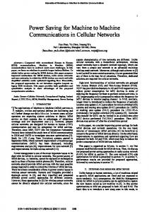
Fig. 1. Proposed EH-PMU implementation in a medical application setting.
voltage gain); and ideally, providing a clean and regulated output voltage under different load conditions. Due to their high efficiency and intrinsic use of energy storage passive elements, most EH-PMUs use either inductor-based switching regulators [14] or switch-capacitor converters [15] to interface the EH transducer with the output load. However, due to the constant switching involved, these solutions tend to introduce large voltage ripple at the output. Although using super/ultra-capacitors alleviates the ripple problem, such devices largely impact the bill-of-materials (BOM) cost and board area. This paper introduces an EH-PMU capable of extracting maximum power from a 3 3 thermoelectric generator (TEG) array via a boost converter (BC) with input resistance tracking capability. Furthermore, a low power, capacitor-less low-dropout voltage regulator (CL-LDO) cascaded with the BC acts as a ripple-reduction mechanism, providing high switching-noise-suppression to the output regulated voltage. The proposed EH-PMU is suitable for operation in a medical application setting as the one illustrated in Fig. 1. Micropelt's MPG-DG655 TEG unit modules [16] are used to build a 3 3 array (electrically modeled with the , Thevenin equivalent). Taking advantage of a skin-environment temper, the array is able ature gradient ranging between 0.23–2.1 to produce a of 200 mV while adopting configurations from all-parallel to all-series unit elements. Whilst can be maintained almost constant via array reconfiguration, the values for range between 19 to 1.53 (due to unit TEG module resistance of 170 ). The BC uses as its input , which is adevoltage and produces a higher voltage, quate to power CMOS circuitry. A CL-LDO cascaded with the BC uses as input to generate its regulated, cleaner ver. Though the better quality is the EH-PMU sion primary output, is also available as a secondary output voltage.
1549-8328 © 2015 IEEE. Personal use is permitted, but republication/redistribution requires IEEE permission. See http://www.ieee.org/publications_standards/publications/rights/index.html for more information.
ZARATE-ROLDAN et al.: A POWER MANAGEMENT UNIT WITH 40 dB SWITCHING-NOISE-SUPPRESSION FOR A THERMAL HARVESTING ARRAY
1919
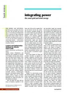
Fig. 2. EH-PMU for a TEG array using a boost converter and a CL-LDO. Fig. 3. Implemented boost converter with MPPT and ZCS schemes.
This paper is organized as follows: Section II provides a system-level description of the proposed EH-PMU. Section III describes the BC used as the EH-PMU front-end and its implementation. Section IV presents the CL-LDO with tunable switching-noise suppression properties used in the EH-PMU back-end. Section V describes the implementation of a Sense-and-Control loop that allows the interaction between front and back-end of the EH-PMU. Section VI presents experimental results of the proposed EH-PMU with front-end and back-end results along with overall efficiency; and finally, Section VI provides this work's conclusions. II. ENERGY HARVESTING POWER MANAGEMENT UNIT In addition to low intrinsic power consumption, for an EH-PMU to be truly viable as a standalone or complementary energy source for noise sensitive blocks, it should: ) Extract maximum power from the EH source; and ) Deliver a CMOS compatible, clean, regulated output voltage. To meet these requirements, the proposed low-power EH-PMU (Fig. 2) uses a boost DC-DC switching converter (BC) as front-end and a CL-LDO as back-end. The BC applies a maximum power point tracking (MPPT) technique at the interface with the TEG array, achieving optimum energy extraction while conditioning the EH-PMU internal voltage levels. The front-end BC brings to usable—higher—CMOS levels at its output (1.8 V). However, demanding voltage regulation and reduced voltage ripple from the front-end, increases the burden and complexity on the BC, which translates in a power hungry BC controller and a low system efficiency. Conversely, using a cascaded CL-LDO provides superior ripple rejection and a steady and regulated output voltage ( , 1.6 V) to the EH-PMU load. The supply-noise-rejecting capabilities of the proposed CL-LDO come from programmable notch-like characteristics in its supply-to-output path. Furthermore, the ultra-low power consumption of the CL-LDO yields high efficiency. Leveraging the superior switching-noise suppression of the CL-LDO, it is possible for our EH-PMU to use an off-chip capacitor in the order of nF. While replacing the supercapacitor [9] with a nFreduces the long-term energy storage capabilities, it also considerably reduces the board area and bill-of-materials expenses. In turn, the regulated output voltage at is an inexpensive solution, suitable for loads with low supply-ripple and low current requirements [4], [5]. To complement the EH-PMU, a Sense-and-Control (SaC) loop is implemented using an external microcontroller. The SaC determines the BC average switching frequency and generates tuning signals for the CL-LDO to place a notch around . As a result, significant ripple reduction at the EH-PMU output is obtained and experimentally demonstrated.
Fig. 4. Capacitive divider for
extraction [10].
III. ENERGY HARVESTING POWER MANAGEMENT UNIT FRONT-END The EH-PMU front-end uses the BC shown in Fig. 3, which employs zero current switching (ZCS) and MPPT techniques to improve its efficiency. As suggested in [10], [17], MPPT is achieved by matching the resistance of the source (TEG array, ) to the input resistance of the harvester . In Fig. 3, of the the MPPT loop modulates the switching frequency BC until the condition is reached. It is during each reconfiguration event within the TEG array that the BC must quickly and accurately track and match the new value to ensure continuous maximum power transfer from the array. Once has been matched to , the input voltage for the BC settles at half the TEG array open circuit voltage , indicating that the maximum point for power (MPP) transfer has been reached. Thus, following the MPP under changes due to TEG array reconfiguration requires a dynamic MPPT scheme. For comparison purposes, the threshold is obtained the through a capacitive divider [10] (Fig. 4). During phase TEG-BC connection is opened and is sampled into capacitor . Later, during , the TEG-BC connection is restored is connected in parallel with . Through charge reand distribution, the voltage developed in both and is now equal to (provided ). A. Input Resistance Matching As mentioned in Section I, the TEG array modules can reconfigure their interconnections to take advantage of different temperature gradients naturally available throughout the human body to increase overall system power extraction. For the proposed 3 3 array, the two major scenarios that take into consideration the best/worst case power conditions are the fully par-
1920
IEEE TRANSACTIONS ON CIRCUITS AND SYSTEMS—I: REGULAR PAPERS, VOL. 62, NO. 8, AUGUST 2015
allel and fully series connections of the array, respectively. The design of the EH-PMU was aimed at voltages ranging from 50 mV to 200 mV, which are voltages delivered by a single TEG module under a temperature gradient of approximately 0.23 to 2.1 . The series-parallel connection of the TEG array leads to an ranging from 1.53 to 19 for the series and parallel configurations, respectively. For the design of the BC, Discontinuous Conduction Mode (DCM) was selected due to the low power nature of the application and in order to maintain power consumption to a minimum. For DCM operation, [18] shows that can be approximated to: (1) , , and are the input inductor value, In (1), switching frequency of the BC, and duty cycle of the control signal of NMOS switch ; all in reference to Fig. 3. This prompts the use of a Pulse Frequency Modulation (PFM) scheme to control . Although both and are , the -quadratic dependency on capable of modulating requires a highly precise and power hungry control scheme. Hence, is selected as the control variable to mainby setting the value of at tain a linear control of 50% of the switching period. A second approach to minimize power consumption by the BC was to restrict the range over which the converter will operate to low values. This reduces the total dynamic power consumption for the system. Choosing a 5 mH inductor as sets the value of to vary from 38 kHz to 500 Hz for the required values to match. While this value might seem high, it is not uncommon for integrated energy harvesting systems to use off-chip inductors with similar or higher values [19]. In our case, the selected value allows successful operation using low switching frequencies, which in turn reduces the overall power consumption and maximizes the global efficiency. B. Maximum Power Point Tracking Loop As described in [10], the MPPT scheme possesses a matching range over which the system can assure maximum power extraction. The MPPT scheme allows for rapid maximum power extraction when changes occur on the equivalent . Similar to a phase locked loop (PLL), loop stability is a primary concern in order to avoid unstable responses from the system when an change occurs. The block diagram in Fig. 5 presents the small-signal model that makes up the MPPT system of Fig. 3, where and are the halved open circuit voltage of the TEG array and the input voltage of the BC, correspondingly. The variables , , , and are the linear gain of the comparator, charge pump bias current, filter transfer function, and controlto-input transfer function for the BC, respectively. Hence, the open loop transfer function of the complete MPPT loop is given by: (2) , is obtained The control-to-input transfer function, following [18]. Assuming steady-state operation, both the input source and the BC output voltage can be presumed to be AC ground during the small-signal analysis due
Fig. 5. Control loop and equivalent small-signal model for PFM BC.
to the 10 nF . Under these assumptions, the small-signal model shown in Fig. 5 is used to analyze the MPPT loop stability. The parameters and , (Fig. 5) are obtained via three dimensional Taylor series expansions of the average input and output voltages and duty cycle [20] at steady-state operation. The variable , seen in both Fig. 3 and Fig. 5, is the VCO control voltage coming from the filter block, . transfer Using the simplified model of Fig. 5, the function includes the effect of the VCO linear gain and yields: (3) where (4) (5) Extending the charge-pump-based PLL analogy, an external, second order passive loop filter formed by capacitors and resistor (Fig. 3) is used to enhance the MPPT loop response. In this case, (2) becomes: (6) of 100 mV, with of 100 nF, of 10 Assuming a of 500 , for a , and of 100 nA nF, and (charge pump current [21]); in the mid-value of (775 ), the MPPT loop has unity gain frequency (UGF) of 2 kHz, and phase margin (PM) of 88 . Thus, a second order allows for a stable system response over a wide range of equivalent resistance values and a rapid response after a TEG array reconfiguration. C. Zero Current Switching Scheme Reducing stress on monolithic components and improving efficiency are important goals for any switching converter to reach. In order to address both these issues, a zero current switching (ZCS) technique is employed. The ZCS scheme shown in Fig. 6 minimizes the inductor current losses through the PMOS switch, , and is implemented following [22]. The ZCS is performed via a skewed voltage peak detector in the node. This voltage is next compared to a fixed reference, . The comparison result is used to generate voltage , which eventually regulates the on/off time of (Fig. 6), reducing the inductor current losses.
ZARATE-ROLDAN et al.: A POWER MANAGEMENT UNIT WITH 40 dB SWITCHING-NOISE-SUPPRESSION FOR A THERMAL HARVESTING ARRAY
1921
Fig. 7. Simple CL-LDO structure.
CL-LDO structure of Fig. 7 to determine its fundamental PSR limits.
Fig. 6. Zero Current Switching Tracking loop implementation [22].
As discussed in [14], when is turned off and 's current has not been fully delivered, an associated voltage surge is perceived at . This voltage surge is proportional to the rate when is off. Ideof change of the remaining current in ally the inductor current would fall to zero before the PMOS is switched off, thus, reducing any losses associated with this switch. A dynamic Zero Current Switching Tracking (ZCST) loop [22] is implemented to minimize the potential losses associated with negative inductor current. IV. ENERGY HARVESTING POWER MANAGEMENT UNIT BACK-END Even though the EH-PMU front-end successfully performs MPPT from the TEG harvester and develops an output voltage sufficiently high to drive low power circuits, exhibits a large voltage ripple. Thus, directly using to power electronic circuits might lead to unacceptable performance or failure of the energy-recipient circuits, particularly in the case of circuits with high supply-noise sensitivity. The proposed EH-PMU incorporates an LDO as its back-end to solve this problem. Although using an LDO to reduce the ripple in and produce a quiet voltage, , might seem as a straightforward solution; the high end-to-end efficiency expected from the EH-PMU limits the power that can be used to design a high performance LDO. Furthermore, to reduce the cost of the required external components of the solution, a capacitor-less LDO (CL-LDO) is used. For the CL-LDO in the EH-PMU back-end to successfully attenuate the magnitude of the ripple in , the CL-LDO should possess high power supply rejection (PSR) at and around the ripple frequency . Multiple CL-LDO advanced structures with notorious PSR improvements have been recently proposed [23]–[27]. However, most of these works report current consumptions from several to a few hundreds of and are designed to deliver load currents between 20 to 100 mA. Nonetheless, in the case of a CL-LDO targeted for EH applications, the available current to deliver to the load might be scarce and dependent on the conditions surrounding the EH transducer (thermal gradient between the TEG plates). Thus, investing even ten to get a well regulated and ripple-reduced output voltage represents a major cut to the available current to be delivered to the load, and can seriously harm the end-to-end system's efficiency. Thus, to reduce the CL-LDO complexity and quiescent current, it is convenient to analyze the basic
A. Basic CL-LDO In the CL-LDO of Fig. 7, the error amplifier (EA) is assumed to be a single stage differential pair amplifier; the pass transistor is a PMOS device; resistors form a feedback voltage divider, ; and is selected such that (assuming large loop gain). The load is modeled and capacitor (to account for the load paraby resistor sitic capacitance and/or a small on-chip capacitance). The open loop gain of the CL-LDO in Fig. 7 ( , evaluto ) is given by (7). contains two poles ated from ( and ) and one zero . and represent the DC voltage gain of the EA and , respectively. To approximate the locations of the poles (8) and zero (9), it is assumed that ) is small and ) The EA output conductance, , is smaller than the total output conductance, , formed by and the conductance, . Note that and in (8)-(9) stand for the total 's gate-to-source (includingto-bulk), and gate-to-drain parasitic capacitance, respectively. (7) (8) (9) The approximations for (typically the dominant pole) and are consistent with the expressions found in previous works [28]. However, due to the low in our application, the transconductance and values might have similar is provided in magnitudes. Thus, a detailed expression for (8). As expected, satisfactory phase margin and loop stability can only be achieved if enough separation exists between and for all of interest. In this case, loop stability can be achieved using Miller compensation at expense of reduced gainbandwidth product (GBW) and increased power consumption. Similarly, the PSR of the CL-LDO in Fig. 7 is given in (10). has two zeros and two poles which are approximated in (11) and (12), respectively. Analyzing (10), it can be concluded that the DC PSR of the CL-LDO starts to degrade at , and in order to improve the PSR performance, should be pushed to higher frequencies. Unfortunately this solution generally entails increased power consumption, which cannot be tolerated in a CL-LDO for low power EH applications.
(10)
1922
IEEE TRANSACTIONS ON CIRCUITS AND SYSTEMS—I: REGULAR PAPERS, VOL. 62, NO. 8, AUGUST 2015
(11)
(12) in Nonetheless, it is interesting to note that and in share the same expression. This means that the pole at the gate of in is reflected as a zero in . This fact will be later recalled as the basis of the proposed PSR enhancement technique. B. Proposed CL-LDO In the two-stage EH-PMU, the ripple noise present at (front-end-output/back-end-input) exhibits the strongest components at and around the switching frequency . This localized noise nature suggests that it is not strictly necessary for the CL-LDO to exhibit uniformly high PSR across the frequency spectrum (from DC through ), and as long as the PSR at is adequate, most of the switching noise at will not be present at the PMU output voltage . Thus, a low power CL-LDO capable to emphasize its PSR at particular frequencies is implemented as the EH-PMU back-end. For higher flexibility, the CL-LDO PSR characteristics can be modified via a programmable bank of capacitors to reject particular frequencies within the range of interest. , is One way for the CL-LDO to selectively reject a given to make its PSR transfer function to partially resemble a notch filter. If said notch is centered at , the main CL-LDO ripple noise components can be significantly attenuated at the PMU output. This approach allows improving the PSR performance without using an LDO with high PSR for all frequencies (which in general results in large power consumption). The concept of using a tunable, continuous time notch/bandreject filter to remove noise at specific, well-identified frequencies has been widely exploited in wireless receivers [29]–[31]. In such applications, the notch filter can be merged with the low-noise amplifier (LNA) [29] at the receiver front-end to implement either an image rejection filter or to get rid of strong blockers [30]. Notch filtering has also been demonstrated using a broadband resistive feedback LNA with embedded feedforward to improve blocker rejection at third and higher oscillator harmonics [31]. The transfer function of a second order symmetrical notch filter is shown in (13) [32]. (13) Note that whereas the poles of (13) can be real or complex, the zero-pair is complex. The natural frequency is represented by , is the gain in the passband, and is the quality factor. Thus, to grant notch filter characteristics to the PSR of the CL-LDO in Fig. 7, a pair of complex poles should be placed at the gate of , such that, due to the loop action, are reflected as complex zeros in the PSR transfer function. Including a notch in the CL-LDO PSR transfer function using techniques similar to the presented in [29]–[31] is neither straightforward nor convenient. In the case of an LNA with notch filtering, the notch is generally placed at frequencies out of the band of interest (to reject interferers and out-of-band blockers) and the additional phase shift at the notch frequency,
Fig. 8. Transistor-level implementation of the proposed CL-LDO.
, does not affect the correct reception of the transmitted signals within the system bandwidth. However, in the case of the LDO, the loop GBW is maximized (within power budget) to have fast transient response and extended noise suppression. Thus, when the is lower than the LDO GBW, the phase shift due to the required complex poles at the gate of (responsible for generating the notch in the PSR transfer function) might jeopardize the loop stability and render the LDO unstable. For this reason, any modification made to include complex poles at the gate of in the circuit of Fig. 7 should not affect the loop stability. Consider the circuit of Fig. 8 where the EA of the CL-LDO in Fig. 7 is implemented at the transistor level using an NMOSinput differential pair . Shown in a dashed line box in Fig. 8 is an auxiliary circuit used to modify the PSR characteristics of the CL-LDO and simultaneously stabilize the regulator. The auxiliary circuit is composed of transistor (biased via and ), a coupling capacitor and a series load. To understand the function of the auxiliary circuit, the operation of the CL-LDO in Fig. 8 should be analyzed from two different perspectives: circuit stability and PSR. C. CL-LDO Stability If in Fig. 8 is a clean bias voltage, for the loop-stability purposes the auxiliary circuit appears only as an equivalent passive load. This load is formed by the parallel of branch and the series . While , the series , and are passive elements, is the parallel of output resistance and the output resistance of the curthe rent source . This is further illustrated in Fig. 9, where the small signal model of the loop is shown (note that for and in Fig. 8 are assumed clean voltthis analysis ages -analog ground-). In Fig. 9, and represent the transconductances of the EA and , respectively, is is the gate-to-drain parasitic cathe EA output conductance, pacitance of and is the total parasitic capacitance at the gate of (gate-to-source plus gate-to-bulk parasitic capacitances mainly). The expression for the equivalent admittance of the auxiliary circuit seen in the loop is given in (14), where and denote the conductances of and . The expressions for the zeros and pole of (14) are given in (15) and (16), respectively.
(14) (15) (16)
ZARATE-ROLDAN et al.: A POWER MANAGEMENT UNIT WITH 40 dB SWITCHING-NOISE-SUPPRESSION FOR A THERMAL HARVESTING ARRAY
to
1923
Using (14), it can be shown that the open loop gain (from ) of the circuit in Fig. 8 can be simplified to (17)
(17) The loop gain of the proposed CL-LDO (17) has three zeros and four poles. Two of the zeros arise directly from the auxiland the third zero is the same as iary circuit the zero in the basic CL-LDO in (7) (i.e. in (9)). Conversely, it is hard to determine useful, closed-form expressions for the poles of (17) unless the following application-specific (low power EH system) assumptions are made: ) ; ) provides only low levels, thus and are both ; ) is low; and ) Both EA and operate at low inversion levels, however (e.g. in Fig. 8). The approximated, design-friendly expressions of the zeros and poles of (17) are summarized in Table I. Interestingly, and virtually cancel each other, which reduces (17) to a two-zero, three-pole system. Moreover, and can be regarded as high frequency time constants, further simplifying the CL-LDO stability analysis to a two-pole one-zero system where the GBW can be approximated as . and (Fig. 7) have been removed in Feedback resistors the proposed CL-LDO (Fig. 8); this yields and reduces the CL-LDO quiescent current consumption. Note that the coupling action of enables the interaction of the auxiliary circuit with the regulation loop, allowing for the bias point to be determined by the regulation loop. The required CL-LDO range is determined based on the min and max theoretical power that can be extracted from the TEG array; this is given by . For the mid-range ), the min-max range is temperature gradient (100 mV . In the ideal 100% EH-PMU efficiency scenario, these values translate to a CL-LDO range of about 4–300 @ 1.6 V . The Bode plot of the loop gain is shown in Fig. 10 for a of 10 pF and of 4 , 300 and 1 mA. For the target values, the UGF varies from 480–870 kHz and the PM is better than 48 in the worst stability case, proving that the adopted frequency compensation resulting from the auxiliary circuit is suitable for this application. In the out-of-range case , but the of 1 mA, the UGF is reduced due to the action of PM is 99 and the loop is still stable. D. CL-LDO PSR The PSR small signal model of the proposed CL-LDO is shown in Fig. 11. Unlike the small signal representation for the loop gain in Fig. 9, for PSR-purposes transistor is directly on the input signal path to the output . As a result, implements a common-gate stage whose output is AC-coupled (via ) to a load formed by the series circuit and the gate of . In the model of Fig. 11, the EA is represented as
Fig. 9. Small signal model to analyze stability in the proposed CL-LDO. TABLE I PROPOSED CL-LDO LOOP POLES AND ZEROS
Fig. 10. CL-LDO loop gain for different
values (postlayout simulation).
in [33], [34]. Conductances , and , and current source model the used Type-A EA [34] ( in Fig. 8). Except for ( transconductance) and and (output conductances of and current mirror in Fig. 8, respectively) all the variables are as previously defined. It can be shown that the PSR of the Fig. 11 model contains a total of four zeros and four poles, but more importantly, the PSR expression can be arranged as (18). (See equation at the bottom of the page.) Under the same )– ) assumptions of Section IV-C, the location of the poles of (18) can be approximated as shown in Table II. Note that the four poles are real and exist in
(18)
1924
IEEE TRANSACTIONS ON CIRCUITS AND SYSTEMS—I: REGULAR PAPERS, VOL. 62, NO. 8, AUGUST 2015
Fig. 12. Simplified PSR block diagram for the proposed CL-LDO. Fig. 11. Small signal model to analyze PSR in the proposed CL-LDO. TABLE II PROPOSED CL-LDO PSR POLES AND ZEROS
the LHP. However, of particular interest is the location of the zeros since, as previously discussed, the PSR degradation onset occurs at the location of the most dominant zero in the PSR , but also any notch-filter-like behavior will stem from can the characteristics of the zeros. While the location of be controlled with , it is fair to assume this is the dominant zero due to the presence of and ( gain) in the expression. Also in Table II, can be safely regarded as a high-frequency zero since it is dependent on small parasitic capacitance (due to small ). More relevant for the . operation of the overall EH-PMU is the interaction of Although these two zeros do not directly appear in (18), their effect is captured in the form of a second order equation in the numerator of (18). It can be shown that if the damping factor of the second order equation ( , in Table II) is smaller than 1, and generate a complex pair with non-zero real compo. nent, producing a notch at the frequency Assuming a fixed, small (a few pF due to small ), the notch can be tuned via , and . Furthermore, ( ,) is implemented using a high-R resistor with a total value of , leaving and as the notch-tuning elements. To account for potential parameter variations, a programmable capacitor bank is used to realize . A 4-bit external control signal is used to choose between 16 different values (for a maximum of 40 pF). A second degree of programmability is to vary as needed. For added by externally setting assumption ) in Section IV-C to remain valid, a second 4-bit capacitor bank for is also implemented and set accordingly bank was first (for a maximum of 80 pF). The need for the highlighted in [35], where a more complex expression for is presented since assumption ) is not made. According to the expression, a combination of the aforementioned values requires a smaller than 1 to produce a notch within the target range. Such values can be obtained with less (Fig. 8), which complies with the low power than 1 requirement of the CL-LDO.
Although the PSR is inversely proportional to the loop gain [34], notice that the zeros in Table II (PSR) do not directly correspond to the poles in Table I (loop gain) and vice versa. This property of the proposed CL-LDO allows to have a set of complex zeros in the PSR transfer function without complex poles in the loop gain. To understand the beneficial pole-zero disparity between (17) and (18), consider Fig. 12 where a simplified PSR block diagram of the CL-LDO is shown. , and represent the frequency-dependent gain of the EA, and auxiliary circuit (dashed line box in Fig. 11), respectively. Paths 1, 2 and 3 represent the -to- noise paths affecting the PSR. Assuming large loop gain, path 1 suffers large attenuation at , thus only paths 2 and 3 are considered in this conceptual analysis Solving for in Fig. 12 yields (19), where is the direct path from -to- due to and . Condensing the effects of the auxiliary circuit in , it can be shown that (19) has four poles and four zeros if the individual , , , and have: one-pole (at ); one-pole (at ) and one-zero (due to and ); two poles and two zeros; and one pole (at ), respectively. Furthermore, (19) approximates (18) under the assumptions made and introduces a notch in the PSR without compromising the loop stability. This is due to being purely passive for stability purposes (Fig. 9) but active for PSR purposes (Fig. 11), thus (17) and (18) experience different effects from . (19)
V. SENSE-AND-CONTROL LOOP An off-chip Sense-and-Control (SaC) loop was implemented using the low power, 8-bit Microchip's microcontroller PIC16F1783. After the BC has reached MPP and locked into a nearly constant (for a given load current), the PIC determines the average and uses this value to map it on a look-up table (LUT). The LUT contains the appropriate control signals for the CL-LDO such that the notch is placed at for maximum voltage ripple suppression. For every of interest, the LUT contains two calibration entries, one for the analog value (generated through the PIC's 8-bit digital-to-analog converter with a resolution better than 4 mV in a 0–1 V range), and a second entry with the proper 8-bit digital word to tune the and capacitor banks (4 bits per bank). Once the tuning is completed, the CL-LDO notch is placed in the vicinity of , effectively rejecting the undesired BC switching noise. The CL-LDO notch can be tuned as often as seconds ( is the number of -periods used ). In our prototype, a high PSR is obtained by to estimate ( of 100), which allows for opaccurately measuring timum notch placement. Since slow load changing conditions
ZARATE-ROLDAN et al.: A POWER MANAGEMENT UNIT WITH 40 dB SWITCHING-NOISE-SUPPRESSION FOR A THERMAL HARVESTING ARRAY
1925
Fig. 13. PSR measurement circuit.
are assumed, the notch tuning is performed with a 1-second interval. Note that a slow update rate avoids unnecessary power consumption on the external PIC (70 in this case). While our proof-of-concept uses an off-chip SaC loop, notice that an on-chip finite-state-machine (FSM) could implement the SaC loop. Within the FSM, a synchronous counter could be used to measure and directly tune the banks of capacitors with its final count. Similarly, this count (binary word) could be used in a basic digital-to-analog converter to generate the analog value for notch calibration purposes. A. Look-Up-Table Contents Optimization While the LUT can be filled using data obtained at the design and simulation stage, such calibration entries might require small adjustments to compensate for potential process variations. A straightforward way to verify the adequacy of the initial calibration estimates to tune a notch at frequencies is with a one-time CL-LDO PSR characterization using said estimates and updating the LUT as necessary. Alternatively, it is possible to perform a foreground, automatic PSR estimation to determine if the initial calibration estimates provide suitable notch control and noise rejection. If the PSR is not satisfactory for a particular , the calibration entry for is then adjusted accordingly and updated in the LUT. The circuit in Fig. 13 can be used for PSR estimation. In this approach, a peak detector based on signal amplification and partial rectification [36] is employed to estimate the supply noise at the CL-LDO input and output. Before the measurement, the initial calibration estimates for a notch at are used. After the measurement is completed, the PIC used for the SaC loop can sample the results at and process them to obtain a PSR indicator. If the PSR indicator is satisfactory, the calibration entries for are confirmed and marked as reliable in the LUT. Otherwise, if the initial calibration estimates are off after fabrication (resulting in insufficient PSR due to imperfect notch tuning), the PIC runs a search algorithm (Fig. 14) to find a new calibration estimate that provides a notch (and higher PSR) at . Once the new calibration entries are determined, the LUT is updated. This process is repeated for every of interest. Note that the suggested, on-board PSR measurement method can be seamlessly integrated, and while the amplifiers required might consume additional power, the power overhead is experienced only during a short period of time required for the LUT optimization, after which both amplifiers can be shut-down.
Fig. 14. LUT optimization algorithm.
Furthermore, additional, more complex techniques to measure PSR on-chip can be used [37]. VI. MEASUREMENTS The EH-PMU was designed and fabricated in 0.5 CMOS process. Fig. 15 presents the testbench setup and die microphotograph, with an active area of 0.93 . Resistance matching between the EH-PMU front-end (BC) was performed by varying the series impedance of a 3 3 TEG array composed of MPG-DG655 modules. While the details of the array reconfiguration are out of the scope of this work, a total of 42 switches [10] enable any possible parallel/series combination of the units in the array. These interconnecting switches can be controlled by the same PIC implementing the SaC loop. By monitoring the output of an off-the-shelf temperature sensor, the PIC can decide the state of the interconnecting switches and reconfigure the array. Resistance variation step was performed from 19 to 1.53 in order to make sure stability is correctly achieved under drastic loop parameter variations. Fig. 16 shows that the correct MPP is achieved of 100 mV for both TEG resistance equivalencies. Broader ranges of matching can be accomplished via a tradeoff between and value. The BC and CL-LDO outputs are shown in Fig. 17 (upper and . Before lower signals, respectively) for a load current of 10 the notch is introduced (Fig. 17(a)) the CL-LDO output shows an attenuation of the switching noise of 6 dB. However, when
1926
IEEE TRANSACTIONS ON CIRCUITS AND SYSTEMS—I: REGULAR PAPERS, VOL. 62, NO. 8, AUGUST 2015
Fig. 15. Die microphotograph and testbench setup.
Fig. 16. Correct MPPT is achieved through PFM control loop.
Fig. 18. CL-LDO measured PSR with notch tuning range of 15–65 kHz.
Fig. 17. Switching noise suppression from CL-LDO.
the CL-LDO tuning is completed and the notch in the PSR has been properly placed (Fig. 17(b)), the attenuation reaches 40 dB. The measured CL-LDO PSR is shown in Fig. 18 for three combinations of bank, bank and . The total range over which the notch can be programmed is roughly between 15 , the kHz to 65 kHz. While the BC might switch at intrinsic, low-frequency PSR of the CL-LDO can successfully attenuate the ripple at these values. Although the optimum , ripple rejection is achieved when the notch is centered at in the event of slight variations after the notch has been tuned, the switching noise at will still experience attenuation due to the steep skirt around the center notch frequency (e.g., a notch centered at 27 kHz has 36 dB suppression at 32 kHz, this is of 18.5%). From the CL-LDO load transient response to a 4–300 step (Fig. 19), the measured load regulation is 17 mV/mA. Interestingly, even though the modest bandwidth of the CL-LDO results in a settling time of 5 , this recovery interval represents less than 3% of the total Rx-to-Tx or Tx-to-Rx turnaround time in IEEE 802.15.4 standard-compliant devices [38]. Thus, an ultra-low power radio powered by the proposed EH-PMU could afford a frequency synthesizer with a settling time of
Fig. 19. CL-LDO load transient response to a 4
to 300
step.
nearly 187 and still meet the IEEE 802.15.4 standard (which specifies a turnaround time of 12 symbol periods or 192 @ 62.5 ksymbol/s). Influenced by the small on-chip and low bias current available to drive the gate capacitance of , the Fig. 19 meadesurement also shows that the voltage undershoot parts up to 380 mV from the nominal . Despite its short duration, there might be load circuitry for which this undershoot could cause undesired operation. When necessary, it is possible to combine the proposed CL-LDO with voltage spike-triggered dynamic biasing techniques [39] to reduce the magnitude of the voltage dip, at the expense of increased current consumption.
ZARATE-ROLDAN et al.: A POWER MANAGEMENT UNIT WITH 40 dB SWITCHING-NOISE-SUPPRESSION FOR A THERMAL HARVESTING ARRAY
1927
REFERENCES
Fig. 20. End-to-end system efficiency. TABLE III PERFORMANCE SUMMARY AND COMPARISON
As shown in Fig. 20, the overall maximum system end-to-end efficiency was measured at 57.57% ( of 1.8 V and of 1.6 V) for input voltages of 140 and 190 mV. The (1 in the total EH-PMU power consumption is 3.6 BC and 2.6 in the CL-LDO). Table III presents the overall system performance for the proposed EH-PMU compared to state-of-the-art systems. The total power consumption does not take into account the power consumed by the microcontroller SaC implementation. VII. CONCLUSION An energy harvesting power management unit (EH-PMU) based on a combination of a boost converter and a capacitorless LDO (CL-LDO) with high efficiency and enhanced noise suppression has been presented. The boost converter delivers MPPT from an array of TEG devices through a frequency modulation scheme. The matching scheme is capable of correctly match from 19 to 1.53 . The CL-LDO includes an auxiliary circuit for enhanced PSR. A notch at the switching frequency of the boost converter is added in the CL-LDO PSR transfer function. The EH-PMU employs a Sense-and-Control loop to send the switching frequency information from the boost converter to the CL-LDO to correctly shift the notch to the switching frequency. End-to-end system efficiency of 57.57% is achieved by the EH-PMU, and 40 dB noise suppression at the switching frequency is measured. The proposed power consumption/power delivering capabilities of the EH-PMU are suitable for energy harvesting assisted devices in the 100 s of range. ACKNOWLEDGMENT The authors would like to thank MOSIS for chip fabrication.
[1] Y. Long, P. Harpe, M. Osawa, Y. Harada, K. Tamiya, and C. Van Hoof et al., “A 680 nA fully integrated implantable ECG-acquisition IC with analog feature extraction,” in IEEE Int. Solid-State Circuits Conf. (ISSCC) Dig. Tech. Papers, 2014, pp. 418–419. [2] D. Bol, J. De Vos, C. Hocquet, F. Botman, F. Durvaux, and S. Boyd et al., “SleepWalker: A 25-MHz 0.4-V submicrocontroller in 65-nm LP/GP CMOS for low-carbon wireless sensor nodes,” IEEE J. Solid-State Circuits, vol. 48, no. 1, pp. 20–32, Jan. 2013. [3] L. Zhicheng, M. Pui-In, and R. Martins, “A 0.5 V 1.15 mW 0.2 Sub-GHz ZigBee receiver supporting 433/860/915/960 MHz ISM bands with zero external components,” in IEEE Int. Solid-State Circuits Conf. (ISSCC) Dig. Tech. Papers, 2014, pp. 164–165. [4] M. Lont, D. Milosevic, G. Dolmans, and A. H. M. van Roermund, “Mixer-first FSK receiver with automatic frequency control for body area networks,” IEEE Trans. Circuits Syst. I, Reg. Papers, vol. 60, no. 8, pp. 2051–2063, Aug. 2013. [5] J. Pandey and B. P. Otis, “A sub-100 MICS/ISM band transmitter based on injection-locking and frequency multiplication,” IEEE J. Solid-State Circuits, vol. 46, no. 5, pp. 1049–1058, May 2011. [6] S. Bandyopadhyay, P. P. Mercier, A. C. Lysaght, K. M. Stankovic, and A. P. Chandrakasan, “A 1.1 nW energy harvesting system with 544 pW quiescent power for next-generation implants,” in IEEE Int. Solid-State Circuits Conf. (ISSCC) Dig. Tech. Papers, 2014, pp. 396–397. [7] H. Ito, S. Masui, Y. Momiyama, A. Shirane, M. Takayasu, and Y. Yoneda et al., “A 2.3 pJ/bit frequency-stable impulse OOK transmitter powered directly by an RF energy harvesting circuit with 19.5 dBm sensitivity,” in Proc. IEEE Radio Freq. Integr. Circuits (RFIC) Symp., 2014, pp. 13–16. [8] A. Shrivastava, Y. K. Ramadass, S. Khanna, S. Bartling, and B. H. Calhoun, “A 1.2 SIMO energy harvesting and power management unit with constant peak inductor current control achieving 83–92% efficiency across wide input and output voltages,” in Symp. VLSI Circuits Dig. Tech. Papers, 2014, pp. 1–2. [9] E. E. Aktakka and K. Najafi, “A micro inertial energy harvesting platform with self-supplied power management circuit for autonomous wireless sensor nodes,” IEEE J. Solid-State Circuits, vol. 49, no. 9, pp. 2017–2029, Sep. 2014. [10] S. Carreon-Bautista, A. Eladawy, A. N. Mohieldin, and E. Sanchez-Sinencio, “Boost converter with dynamic input impedance matching for energy harvesting with multi-array thermoelectric generators,” IEEE Trans. Ind. Electron., vol. 61, no. 10, pp. 5345–5353, Oct. 2014. [11] S. Bandyopadhyay and A. P. Chandrakasan, “Platform architecture for solar, thermal, vibration energy combining with MPPT and single inductor,” IEEE J. Solid-State Circuits, vol. 47, no. 9, pp. 2199–2215, Sep. 2012. [12] Z. Yanqing, Z. Fan, Y. Shakhsheer, J. D. Silver, A. Klinefelter, and M. Nagaraju et al., “A batteryless 19 MICS/ISM-band energy harvesting body sensor node SoC for ExG applications,” IEEE J. SolidState Circuits, vol. 48, no. 1, pp. 199–213, Jan. 2013. [13] D. Mengmeng and L. Hoi, “A high-efficiency auto-reconfigurable SITIDO boost/buck regulator with input power conditioning for energy-harvesting applications,” in Proc. IEEE 55th Int. Midwest Symp. Circuits Syst. (MWSCAS), 2012, pp. 1092–1095. [14] E. J. Carlson, K. Strunz, and B. P. Otis, “A 20 mV input boost converter with efficient digital control for thermoelectric energy harvesting,” IEEE J. Solid-State Circuits, vol. 45, no. 4, pp. 741–750, Apr. 2010. [15] I. Doms, P. Merken, C. Van Hoof, and R. P. Mertens, “Capacitive power management circuit for micropower thermoelectric generators with a 1.4 controller,” IEEE J. Solid-State Circuits, vol. 44, no. 10, pp. 2824–2833, Oct. 2009. [16] Micropelt, 2013, MPG-D655 thin film thermogenerator [Online]. Available: http://micropelt.com/downloads/datasheet_mpg_d655.pdf, Accessed: [Mar. 4 2015] [17] K. H. Hussein, I. Muta, T. Hoshino, and M. Osakada, “Maximum photovoltaic power tracking: An algorithm for rapidly changing atmospheric conditions,” IEE Proc. Gener., Transm., Distrib., vol. 142, no. 1, pp. 59–64, Jan. 1995. [18] B. Arbetter, R. Erickson, and D. Maksimovic, “DC-DC converter design for battery-operated systems,” in Proc. IEEE 26th Ann. Power Electron. Specialists Conf. (PESC), 1995, vol. 1, pp. 103–109. [19] T. Ying-Khai and P. K. T. Mok, “Design of transformer-based boost converter for high internal resistance energy harvesting sources with 21 mV self-startup voltage and 74% power efficiency,” IEEE J. SolidState Circuits, vol. 49, no. 11, pp. 2694–2704, Nov. 2014.
1928
IEEE TRANSACTIONS ON CIRCUITS AND SYSTEMS—I: REGULAR PAPERS, VOL. 62, NO. 8, AUGUST 2015
[20] R. E. Erickson and D. Maksimovic, Fundamentals of Power Electronics, 2 ed. ed. New York: Springer, 2001. [21] M. Mansuri, “Low-power low-jitter on-chip clock generation,” Ph.D. dissertation, Dept. Electr. Eng., Univ. California, Los Angeles, CA, USA, 2003. [22] S. Carreon-Bautista, C. Erbay, A. Han, and E. Sanchez-Sinencio, “Power management system with integrated maximum power extraction algorithm for microbial fuel cells,” IEEE Trans. Energy Convers., vol. 30, no. 1, pp. 262–272, Mar. 2014. [23] P. Chang-Joon, M. Onabajo, and J. Silva-Martinez, “External capacitor-less low drop-out regulator with 25 dB superior power supply rejection in the 0.4–4 MHz range,” IEEE J. Solid-State Circuits, vol. 49, no. 2, pp. 486–501, Feb. 2014. [24] G. Jianping and L. Ka Nang, “A 6chip-area-efficient outputcapacitorless LDO in 90-nm CMOS technology,” IEEE J. Solid-State Circuits, vol. 45, no. 9, pp. 1896–1905, Sep. 2010. [25] Z. Chenchang and K. Wing-Hung, “Output-capacitor-free adaptively biased low-dropout regulator for system-on-chips,” IEEE Trans. Circuits Syst. I, Reg. Papers, vol. 57, no. 5, pp. 1017–1028, May 2010. [26] C. SauSiong and C. Pak Kwong, “A 0.9 quiescent current outputcapacitorless LDO regulator with adaptive power transistors in 65-nm CMOS,” IEEE Trans. Circuits Syst. I, Reg. Papers, vol. 60, no. 4, pp. 1072–1081, Apr. 2013. [27] Y. Bangda, B. Drost, S. Rao, and P. K. Hanumolu, “A high-PSR LDO using a feedforward supply-noise cancellation technique,” in Proc. IEEE Custom Integr. Circuits Conf. (CICC), Sep. 2011, pp. 1–4. [28] R. J. Milliken, J. Silva-Martinez, and E. Sanchez-Sinencio, “Full on-chip CMOS low-dropout voltage regulator,” IEEE Trans. Circuits Syst. I, Reg. Papers, vol. 54, no. 9, pp. 1879–1890, Sep. 2007. [29] T. H. Lee, H. Samavati, and H. R. Rategh, “5-GHz CMOS wireless LANs,” IEEE Trans. Microw. Theory Tech., vol. 50, no. 1, pp. 268–280, Jan. 2002. [30] A. Vallese, A. Bevilacqua, C. Sandner, M. Tiebout, A. Gerosa, and A. Neviani, “Analysis and design of an integrated notch filter for the rejection of interference in UWB systems,” IEEE J. Solid-State Circuits, vol. 44, no. 2, pp. 331–343, Feb. 2009. [31] J. W. Park and B. Razavi, “A harmonic-rejecting CMOS LNA for broadband radios,” IEEE J. Solid-State Circuits, vol. 48, no. 4, pp. 1072–1084, Apr. 2013. [32] R. Schaumann, M. S. Ghausi, and K. R. Laker, Design of Analog Filters: Passive, Active RC, Switched Capacitor. Englewood Cliffs, NJ, USA: Prentice-Hall, 1990. [33] J. Torres, M. El-Nozahi, A. Amer, S. Gopalraju, R. Abdullah, and K. Entesari et al., “Low drop-out voltage regulators: Capacitor-less architecture comparison,” IEEE Circuits Syst. Mag., vol. 14, no. 2, pp. 6–26, May 2014. [34] V. Gupta, G. A. Rincon-Mora, and P. Raha, “Analysis and design of monolithic, high PSR, linear regulators for SoC applications,” in Proc. IEEE Int. SoC Conf., Sep. 2004, pp. 311–315. [35] J. Zarate-Roldan, S. Carreon-Bautista, A. Costilla-Reyes, and E. Sanchez-Sinencio, “An ultra-low power power management unit with 40 dB switching-noise-suppression for a 3 3 thermoelectric generator array with 57% maximum end-to-end efficiency,” in Proc IEEE Custom Integr. Circuits Conf. (CICC), 2014, pp. 1–4. [36] M. S. J. Steyaert, W. Dehaene, J. Craninckx, M. Walsh, and P. Real, “A CMOS rectifier-integrator for amplitude detection in hard disk servo loops,” IEEE J. Solid-State Circuits, vol. 30, no. 7, pp. 743–751, Jul. 1995. [37] M. Méndez-Rivera, A. Valdes-Garcia, J. Silva-Martinez, and E. Sánchez-Sinencio, “An on-chip spectrum analyzer for analog built-in testing,” J. Electron. Testing, vol. 21, no. 3, pp. 205–219, Jun. 2005. [38] Low-Rate Wireless Personal Area Networks (LR-WPANs), IEEE Standard 802.15.4-2011, Sep. 2011, Part 15.4. [39] O. Pui Ying and L. Ka Nang, “An output-capacitorless low-dropout regulator with direct voltage-spike detection,” IEEE J. Solid-State Circuits, vol. 45, no. 2, pp. 458–466, Feb. 2010.
Jorge Zarate-Roldan (S'11) received the B.S. degree (Honors) in electrical engineering from the Instituto Tecnologico y de Estudios Superiores de Monterrey (ITESM), Campus Guadalajara, Mexico, in 2004. In the fall of 2007, summer of 2008, and fall of 2012, he interned with Intel Corp. He is currently working toward the Ph.D. degree in electrical engineering at Texas A&M, College Station, TX, USA. His research interests include low-power and high PSR LDOs, and low-power, low-noise oscillators for wireless transceivers. Salvador Carreon-Bautista (S'08) received the B.S. degree in electrical engineering and biomedical engineering from the Instituto Tecnologico y de Estudios Superiores de Monterrey (ITESM), Campus Monterrey, Mexico, in 2007 and 2008 respectively. Since 2008 he has been working towards his Ph.D. degree in electrical engineering. His research interests include ultra-low power and energy efficient power management circuits.
Alfredo Costilla-Reyes (S'14) received the B.S. degree in electrical engineering from Autonomous University of the State of Mexico, Toluca, Mexico, in 2010. He is currently working toward the Ph.D. degree in electrical engineering at Texas A&M University, College Station, TX, USA. He is a scholarship holder from the National Council of Science and Technology (CONACYT) of Mexico. His research interests include ultra-low power and energy efficient power management circuits for energy harvesting applications. Edgar Sánchez-Sinencio (F'92–LF'10) was born in Mexico City, Mexico. He received the degree in communications and electronic engineering (Professional degree) from the National Polytechnic Institute of Mexico, Mexico City, the M.S.E.E. degree from Stanford University, Stanford, CA, USA, and the Ph.D. degree from the University of Illinois at Champaign-Urbana, IL, USA, in 1966, 1970, and 1973, respectively. He has graduated 58 M.Sc. and 44 Ph.D. students. He is a co-author of six books on different topics, such as RF circuits, low-voltage low-power analog circuits, and neural networks. He is currently the TI J. Kilby Chair Professor, University Distinguished Professor and Director of the Analog and Mixed-Signal Center at Texas A&M University, College Station, TX, USA. His current interests are in the area of ultra-low power analog circuits, RF circuits, harvesting techniques, power management, and medical electronics circuit design. Dr. Sánchez-Sinencio is a former Editor-in-Chief of IEEE TRANSACTIONS ON CIRCUITS AND SYSTEMS—PART II and a former IEEE CAS Vice President–Publications. In November 1995 he was awarded a Honoris Causa Doctorate by the National Institute for Astrophysics, Optics and Electronics, Mexico. This degree was the first honorary degree awarded for microelectronic circuit-design contributions. He is a co-recipient of the 1995 Guillemin-Cauer Award for his work on cellular networks. He received the Texas Senate Proclamation # 373 for Outstanding Accomplishments in 1996. He was also the co-recipient of the 1997 Darlington Award for his work on high-frequency filters. He received the IEEE Circuits and Systems Society Golden Jubilee Medal in 1999. He is the recipient of the prestigious IEEE Circuits and Systems Society 2008 Charles A. Desoer Technical Achievement Award. He was the IEEE Circuits and Systems Society’s Representative to the IEEE Solid-State Circuits Society during 2000–2002. He was a member of the IEEE Solid-State Circuits Society Fellow Award Committee from 2002 to 2004. He is a former (2012–2013) Distinguished Lecturer of the IEEE Circuit and Systems Society and currently a member of the IEEE ISSCC Analog Committee.