May 20, 1985 - diameter reflector antenna with a center-supported dipole-disk feed is ... has inspired the name âresonant reflector antenna.â The gain from the.
1386
IEEE TRANSACTIONS ON ANTENNAS AND PROPAGATION, VOL. AP-33, NO. 12, DECEMBER 1985
A Small Dipole-Fed Resonant Reflector Antenna with High Efficiency, Low Cross Polarization, and Low Sidelobes
Abstract-The computer-aided optimization of a small five-wavelength diameter reflector antenna with a center-supported dipole-disk feed is described. The primary radiation is controlled by using a patented beamforming ring to give low cross polarization and low sidelobes due to spillover. The efficiency is maximized by controlling and taking advantage of the multiple reflections between the feed and the reflector. This has inspired the name “resonant reflector antenna.” The gain from the feed reflector resonances is so large that it compensates almost completely for the about 1 dB loss due to center blockage of the aperture.
r. INTRODUCTION
(I,
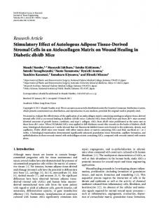
MALL DIPOLE-FED reflector antennas are quite popular in L-band, e.g. in ship earth stations for the INMARSAT satellite communication system. However, if thereflector diameter islessthantypicallysevenwavelengths,such antennas are very difficult to designwithhigh aperture efficiency, low sidelobes, andlow cross polarization. The former is important in order to reduce the physicalsizes of the antennas. The reasons for these difficulties are severe blockage of the aperture caused by the feed, interference from the backlobe ofthe feed, and multiplereflections between the feed and the reflector. This paper describes a reflector antenna whichhasbeendesignedbycomputer-aided control of all these different effects contributing to the aperture efficiency. In particular, the spacing between the feed and the reflector is successfully tuned to resonance. The resulting resonant reflectorantenna(Fig. 1) has very high performance. The theory behind the design is also given (Section II). The starting point ofthe optimization is a parabolic reflector fed by a dipole-disk feed, i.e., a dipole over a plane circular disk [ 1, p. 2451. Using t h i s feed antenna is advantageous as it can befed and supported by means of a stiff coaxial line along the axis of the paraboloid, thereby avoiding blockage from support struts across the aperture. However, the dipole-disk antenna has a much broader radiation pattern in the H-plane (b) than in the E-plane, causing low efficiency andhigh cross- Fig. 1. The resonant reflector antenna with dipole-disk feed and beamforming ring. (a) Photo. @) Geometry. polar sidelobes. This is improved by means of a conducting circular beam-forming ring, which compresses the H-plane pattern to be equal to thatinthe E-plane [2]. The moment maximize the feed efficiency and its subefficiencies [4], and method computer program in [3] isusedtocalculateand by trying to minimize the cross-polar sidelobes (Section ID). optimize the geometry of the feed. This is done by trying to Afterwards, the radiation pattern of the complete reflector antennawiththefeedis calculated and optimized, also by Manuscript received May 20, 1985; revised July 24, 1985. means ofthe moment methodcomputer program. The moment T h e author is with the Electronics Research Laboratory. The Norwegian Institute of Technology, O.S. Bragstads Plass 6 , N-7034 Trondheim-NTH, method requires a long time?but is possible Norway. because to use a the reflector only has five wavelengths
S
I----?\\
0018-926X/85/1200-1386$01.00 O 1985 E E E
I
1387
KILDAL: DIPOLE-FED RESONANT REFLECTOR ANTENNA
diameter. During this computation the feed is located with its phase center coinciding with the focal point of the reflector; the phase center being calculated by the method proposed in [5] and [6]. The radiation patterns andthecorresponding aperture efficiency are calculated for different reflector sizes, showing resonances every time the spacingbetweenthe reflector and the disk aismultiple numberof half-wavelengths (Section N). The final reflector geometry is chosen from the results of these computations. Resonances betweena disk and a reflector are also the main reason for the high efficiency of thebackfire antenna [7]. The resonant reflector antennaisrelatedboth to the backfire antenna and to the reflector antenna, as it takes advantages of both the feed-reflector resonances and the reflector focusing. The results of measurements on a practical model of the resonant reflector antenna are presented, whenexcited for both linear and circular polarization (Section V).
II. FA~ORIZATION OF THE APERTURE EFFICIENCY
as va=vf
(4)
11 +Acb+Afs+Al12
where vf is the feed efficiency, Acb is the contribution from center blockage, Afs is the contribution due tomultiple reflections between the feed and the reflector, and A , is the contribution from the backlobe of the feed. The feed efficiencyqf depends on the shape of the radiation pattern of the feed and on the subtended half-angle $, of the paraboloid. It isdefined in [l] and [ 101. Itcan also be expressed as [4, eq. (22)]
1" CO(e) tan ( 6 / 2 ) dB vf = 2
cot2 ($04
1,
2
0
[ICO(e)12+ IXP(e)12] sin 0 dB
(5)
provided the phase reference point of CO(@ coincides with the focal point of the reflector. vf can be factorized into a Let us assume that the feed antenna is linearly polarized with the dipole parallel to the y-axis. Then, the radiation field number of subeffkiencies, characterizing losses due to spillover, cross polarization, nonuniform aperture illumination, of the feed in a point Pcan be written approximately as and phase errors [4]. It can also be used to define a phase 1 E(7)=- e-jkr [ A(e) sin cp ZB+C(e) cos p ZJ (1) center for the feed, as the feed location which minimizes the r phase error losses [5], [6]. The blockage term Arb is negative and proportional to the where k = 27dX is the waGenumber, 0 is the polar angle, p is aperture area blocked by the feed, i.e., the area of the disk. It the azimuth angle, and where ZBand Z l are unit vectors in the can be written approximately as directions of increasing 0 and (o,respectively. A(@ is the Eplane pattern, and C(0) is the H-plane pattern. The approxiArb = - c b ( d / D ) (6) mation leading to (1) implies that radiation into higher order azimuthal modes is neglected. These modes are described by where d is the diameter of the disk andD is the diameterof the sin ncp and cos np variations of thetwo field componentsfor n reflector, and where the blockage parameter cb is [8, eq. (24)] = 2, 3 , * . They will normally be present in dipole feeds, because the dipole itself is not circularly symmetric about the z-axis. However, if the remaining feed geometry (i.e., in our case the disk and the ring) has circular symmetry, we have experienced that higher order modes can be neglected. Let us now assume that the feed described by (1) is ideally The backlobe term A , can be expressed as [9, eq. (6.35)] excited for circular polarization. This meansthatanother dipoleisadded to the feed, with the samelocation as the original one but orthogonal to it (i.e., parallel with thex-axis), and that this dipole is excited equally strong and exactly in phase quadrature with the original dipole. Then, the copolar circularly polarized radiation pattern CO (e) of the f e d is the where F is the focal length of the paraboloid. The phase term meanof the E- and H-plane pattern, and the cross-polar n/2 comes from the radiation integral over thereflector radiation pattern XP (e) is halfthe difference between thetwo, aperture. The multiple reflection term Afi is very difficult to according to [4, sec. 111. Thus, calculate, as, according to [9], weneedtoknowthefield co(e)= [ A(e) c(e)l/a ( 2 ) scattered from the feedwhen it is illuminated by a plane wave. This effect is therefore also often referred to as feed scattering x q e ) = [A(e)- c(e)l/a. (3) [lo, sec. 3.41. However, it is veryeasy to seethat the following proportionality relation must be valid[9, eq. (6.24)] These are also the co- and cross-polar radiation patterns measured for thelinearlypolarizedfeed in the 45" plane. AB a e - J Z k F . (9) We know that XP (0) = 0. To be able tomaximize the aperture efficiency of an We see from (8) and (9) that A, and Afs depend stronglyon the antenna, it is important to understand the different contribu- focallengththrough the phase terms 2kF and -2kF, tions to it. In our case there is no blockagedue to support struts respectively. The idea behind the resonant reflector antenna is across the aperture. We can then write the aperture efficiency to choose the focal length in such a way that A, and Afs become
-
+
1388
IEEE TRANSACTIONS ON ANTENNAS AND PROPAGATION, VOL. AP-33, NO. 12, DECEMBER 1985
real and positive in order to make up for the losses due to the negative blockage term Acb. III. OPTIMIZATION OF FEEDPATTERN
The feed is a half-wave dipole located about a quarter of a wavelength above a plane circular disk. A beam-forming ring over the dipole is used to improve the radiationcharacteristics, as explained in [2]. The radiation pattern of the dipole-disk antenna is in [2] calculated by using the uniform geometrical theoryofdiffraction [ll] in an approximateway.These calculations are here improved by using the moment method computer program ROT2 [3]. The feedismodeledwithout takingthe center support line into consideration. The feed efficiency is evaluated from the calculated patterns by using (5). The results without the ring and with the ring (for the optimum position ofit) are shown inFig. 2. We see that higher efficiencies are available with the ring than without the ring, but the optimum subtendedangle of the paraboloid is smaller. Furthermore, the level of the first cross-polar sidelobe in the feed pattern XP (e) is strongly reduced by using the ring (Fig. 3). The radiation patterns themselves do not differ significantly from those given in [ 2 ] , and are therefore not shown here. However, we may repeat that the main advantage with thering is thatthesidelobesoutside 6 = $o are strongly reduced in the H-plane, thereby reducing the spillover lobes in the radiation pattern of the complete reflector antenna. It is important to reduce the diameter ofthediskas muchas possible in order to minimize the loss due to center blockage, see (6).However, the feed efficiency decreasesfor small disk diameters. A disk diameter of d = 1.1 X was found to be a good compromise, for which the cross polarization in Fig. 3 also has a minimum. The phase center of the feed is calculated by the method in [5]and [ 6 ] .The results are plotted in Fig. 4. We see that the phase center varies rapidly with the diameter of the disk. For d = 1.1 X it is located 0.25 X above the disk, in the position of the dipole. We are interested in having a good compromise betweenlowsidelobesandhigh efficiency. Therefore, a subtended angle of Go = 60" is chosen for the further optimizations in SectionI V , even though the maximum feedefficiency occurs for $0 = 53" (Fig. 2). The different subfactors of the feed efficiencyfor this gois shown in Table I. We see that the spillover loss is reduced by nearly 0.5 dB by using the ring.
N.OPTIMIZATION OF FEED LOCATION In this section the directive gain of the complete antenna with the paraboloidal reflector and feed is calculated by the ROT2 program. The center support for thefeed is not modelled in the calculations. The calculations are repeated for different reflector sizes, but always with the feed located in such a way that its phase center coincides with the focal point of the paraboloid. This means that the spacing zo between the apex of the paraboloid and the diskzo is = F + 0.25 X, where F is the focal lengthof the paraboloid. $ = 60" = constant in all calculations. The aperture efficiencyofthereflectoris evaluated from the calculated directivity. This is presented in Fig. 5 as a function of the disk-reflector spacing 20. For
Subtended half angle $o Fig. 2.
E
Feed efficiency of dipole-disk with ring as a function of subtended half-angle $o of paraboloid.
-lo
= -15
h
C
.-c0 m .-N -m0
-20 -
a I
(0
With ring
-25 -
(40.032)
0,
0
-30 I 0
I
I
I
I
1.0 1.5 2.0 Diameter of disk [dA]
0.5
I 2.5 I
Fig. 3. Level of first cross-polar sidelobe in 45" plane of radiation pattern of feed.
-e
0.3 r
*
Lo
Y
.c
0.2-
.-
v)
0 [ I
f c
0.1 -
t Q,
0 Q, u)
0.0-
m
I
E
p.
-0.1
I
I
0
I
I
1.0 1.5 2.0 Diameter of disk [d/X]
0.5
2.5
Fig. 4. Location of copolar phase center of radiation pattern of feed (6 = 0 in location of disk and 6 is positive on the dipole side of the disk).
1389
KILDAL: DIPOLE-FED RESONANT REFLECTOR ANTENNA
TABLE I SUBFACTORS OF FEED EFFICIENCYFOR DIPOLE-DISK ANTENNA WITH AND WITHOUTRING (d = 1 . 1 A, $0 = 6 0 " )
without ring Spillover q
SP
Polarization q
PO1 I l l u m i n a t l o n qll1
Phase q Feed efficlency
-
-
0 . 8 9 dB
with rlng
-
0 . 4 3 dB
0 . 5 2 dB
-
0.00 dB
- 0.00
0 . 0 8 dB
0.02 dB 0 . 7 3 dB dB
reflector diameters between 4 X and 5 X: (corresponding to zo between 2 X and 2.5 X in our case). However, this loss is seen to be almost entirely compensated for by the gain due to the feed-reflector resonanceswithin a narrowfrequencyband around the resonance peakat zo = 2.1 X.We can associate this peak with a resonantreflector antenna, as the high efficiency is obtained both from the focussing properties of the reflector and from the feed-reflector resonances. The efficiency peak occuring at zo = 1.6 X is almost entirely a resonance phenomenon, making the antenna very similar to a backfire antenna. V. A PRACTICAL DESIGN
This section describes a resonant reflector antenna designed to satisfy the requirements for INMARSAT ship earth stations. For this application there are two slightly separated frequency bands with center frequencies 1.54 GHz and 1.64 GHz and with bandwidths of about 10 MHz. The total relative bandwidth from 1.535 to 1.645 GHz is about 7 percent, which Moment method is sufficiently narrow to fit within the - 0.3 dB points of the i.e. Incl.also feed scattering resonance peak at zo = 2.1 X in Fig. 5. It was chosen to move 5 -1.5 the 1.64 GHz frequency band slightly closer to the peak than >. the 1.54 GHz band, in order to optimize the performance at YY 1 . 6 4 GHz. 0 LL The antenna is designed from the results of the numerical k W optimization. In addition, the reflector diameter is increased K 2 -2.0 slightly from 4.3 X to 5.5 X at 1.64 GHz,without changing the a W feed-reflector spacing zo, in order to increase the directivity n a from 21.1 dBi to 22.8 dBi at 1 . 6 4 GHz. This is advantageous for the INMARSAT application eventhough the computed aperture efficiency decreases from - 1.5 dBto - 1.8 dB at 1.64GHz.Whenzo= 2.1XandD = 5 . 5 X ~ e g e t $=~73" -2.5 for the subtendedhalf-angle of the paraboloidal reflector. This value of $0 gives a feed efficiency of - 1.95 dB, according to the results in Fig. 2. The center blockage efficiency I 1 + Acbl when evaluated from(6) and (7) becomes - 0.95 dB. This loss is larger than the 0.7 dB blockage loss seen in Fig. 5 for D = -3.0 5.5 X and $0 = 60". The reason is that the blockage parameter 2.0 2.5 3.0 C b is larger when Go = 73", due to the larger aperture taper. FEED POSITION Zo= F+0.25 h ih1 Feed efficiency and blockage give together an efficiency of - 2.9 dB for $0 = 73 " and D = 5.5 X. The overall efficiency 3.0 4.0 5.0 6.O computed by the moment method is - 1.8 dB. Therefore, the CORRESPONDING REFLECTOR DIAMETER Dlh gain from the feed-reflector resonances is in this case with an Fig. 5 . Aperture efficiencies of reflectorantennacalculated by different increased reflector about 1.1 dB, which is slightly more than methods for $0 = 60". for the smaller 4.3 X reflector. We see from Fig. 5 that with the larger reflector diameter it is possible to use the resonance comparison we have also plotted the feed efficiency qj in (5), peakat zo = 2.6 h to get nearly the same overall antenna the feed efficiency plus the center blockage loss (i.e., (4) with efficiency, but zo = 2.1 ?, is better in our case because the Afs = A I = 0 and Acb given by (6)), and the previousone axial length ofthe antenna becomes smaller and thereby makes which included also the backlobe interference represented by it possible to enclose the antenna in a smaller radome. A , in (8). A linearly polarized model has been built, with the dipole We see that theefficiency as calculated by using the moment fedthroughaconventionalbalunlocatedinside the center methodon the completeantennahasresonancepeakseach support tube. The ring is supported by four dielectric rods to time zo is a multiple number of half-wavelengths. We also see the disk. The measuredcopolarand cross-polar radiation that these resonancescannotbeexplained by the backlobe patterns in the 45" plane are shown in Fig. 6. The agreement interference alone. They must therefore be caused by multiple with the computed patterns is very good within the main lobe reflections between the feed andthe reflector, i.e., the term AIS and the first sidelobes, in spite of the fact that the center in (4). The loss due to center blockage is veryhigh for support tubeis not included inthe calculations. The agreement
-
t
, -
..
1390
IEEE TRANSACTIONS ON ANTENNAS AND PROPAGATION, VOL. AP-33, NO. 12, DECEMBER 1985
I#
T H E T A Idsgl
(b) Fig. 6. Co- and cross-polar radiation patterns in 45" plane of resonant reflector antenna. (a) 1 . 6 4 GHz. (b) 1.54 GHz.
2.0
is not so good for the backlobes, mainly due to the limited accuracy ofthe computer program ROT2. We also see that the measuredsidelobelevels are well below INMARSAT's specifications. In addition, the cross-polar sidelobes are less than - 27 dB below the main beam maximum, which is quite good for such a small antenna with a dipole feed. A circularly polarized model has also been built, by using two orthogonal feed dipoles. These dipoles are fed in quadrature by a 3 dB power divider and a 90" delay line, both
located within the center-support tube. The overall performance of the circularly polarized model is also very high. The voltage standing-waveratio of the dipoles have been tuned by conventional techniques to be less than 1.35 at 1.54 GHz and less than 1.20 at 1 . 6 4 GHz. The results as measured directly on the dipoles, with the power divider disconnected, is shown in Fig. 7. The axial ratio is typically0.4 dB in both bands.The power gain of the antenna was measured. A breakdown of the different losses are shown in Table II, showing aperture
1
a
1391
KILDAL: DIPOLE-FED RESONANT REFLECTOR ANTENNA
TABLE I1 MEASUREDGAINS AND MEASURED LOSSES OF PRACTICAL CIRCULARLY POLARIZED DESIGN 1.54 GHz
21.59 dB1
Measured power galn
1.64 G H z .
22.37 dBi
Insertion 1oss.power divider
0.16 dB
0.21
Insertion l o s s , dipoles
0.10 dB
0.02 dB
A x i a l r a t i o loss
0.00 d B
0.00 dB
0 . 3 0 d B I n s e r t i o n0 . 3 0 d B
loss in cable
22.15 dBi
Resultlng directlvlty
Corresponding aperture efficiency Comvuted dlrectlvrty
efficiencies at 1.54 GHz and 1.64 GHz of 63 and 66 percent, respectively. These values differ less than 0.2 dB from the resultscomputedwiththemomentmethod program. The measurement accuracy is estimated to about t 0.2 dB. The efficiencies wouldhavebeenevenhigherwith a smaller reflector diameter, as the mwimum efficiency occurs for a diameter of D = 4.3 X.
CONCLUSION A resonant reflector antenna has been described. This consists of a dipole-disk feed anda paraboloidal reflector with a diameter of about four to sixwavelengths. The spillover sidelobes have been reducedby using a patented ring over the dipole [ 121. The spacing between the feed and the reflector has been controlled in order to take advantage of the backlobe of the feed and of the multiple reflections between the feed and the reflector. The gain from these feed reflector resonances is so large that it compensates almost completelyfor the about 1 dB loss due to center blockage of the aperture. Aperture efficiencies above 70 percent are available within a relative frequencyband of approximately 5 percent. The resonant reflector antenna shows also verygoodsidelobeand crosspolarization performance. The far-out sidelobesare more than 30 dB below the main beam maximum, and the first crosspolarsidelobeis more than 27 dB below the mainbeam maximum. This paper hasshownthat it ispossible to designsmall reflector antennas with much higher efficiency than should be expected from conventional designrules. This has been shown by a thoroughandsystematiccomputer-aidedstep-by-step optimization, basedonsimpleanalyticalmodelsofhow reflector antennas work. ACKNOWLEDGMENT
dB
-
2.0 dB 63 l
22.1 dBi
22.90 dB1
- 1.8
dB
66%
22.8 dBi
power divider. Furthermore, I am grateful to the Norwegian Council for Scientific and Industrial Research (NTNF) for providing the basic financial support for the development of the reflector antenna field at theElectronics Research Laboratory (ELAB)at the NorwegianInstitute of Technology (NTH). REFERENCES S. Silver, MicrowaveAntenna
Theory and Design. New York: Dover, 1965. P-S. Kildal,“Dipole-disk antennawithbeam-forming ring,” IEEE Trans. Antennas Propugat., vol.AP-30, no. 4, pp.529-534,July 1982. 0. Rydal, “A numerical technique to predict scatteringfrom bodies of revolution (User’sguide for the computerprogramR o n ) , ” European Space AgencyReport ESA CR(P)-769, prepared at Tech. Univ. Denmark, Dec. 1975. P-S. Kildal, “Factorization of the feed efficiency of paraboloids and Cassegrain antennas,” IEEE Tram. Antennas Propagat., vol. AP33, no. 8, pp. 903-908, Aug. 1985. -, “Combined E- and H-plane phase-centers of antenna feeds,“ IEEE Trans. Antennas Propagat., vol. AP-31, no. 1, pp. 199-202, Jan.1983. -, “Comments on ‘Phase center calculations of reflector antenna feeds,’ ” IEEE Trans. Antennas Propagat., vol. AP-33, no. 5, pp. 579-580, May 1985. [71 H. W . Ehrenspeck andU. A.Strom, “Short-backfire-antenna: A highly efficient array element,”Microwave J., pp. 47-49, May 1977. [81 P-S. Kildal, “The effects of subreflector diffraction on the aperture efficiency of a conventional Cassegrain antenna-Ananalytical a p proach,” IEEE Trans. Antennas Propagat., vol. AP-31, no. 6, pp. 903-909,Nov.1983. -, “Characterization of feedsfor paraboloids:Feed efficiency, phase center definition and feed scattering,” Electron. Res. Lab. Rep. STF44 A 83180, Trondheim, Norway, Oct. 1983. W . V. T. Rusch and P. D. Potter, Analysis of Reflector Antennas. New York: Academic, 1970. R. G. Kouyoumjian and P. H. Pathak, “A uniform geometrical theory of diffraction for an edge in a perfectly conducting surface,” Proc. IEEE, VOI. 62, pp.1448-1461, NOV. 1974. GB t 121 P-S. Kildal, “Dipoleantenna,” NorwegianPatent810972and Patent Application 8208299.
The author acknowledges the collaboration with the engineers at A/S Elektrisk Bureau during the development of the resonant reflector antenna for their INMARSAT ship earth station SATURN. I am grateful to Erling Ellingsen for doing Per-Sion Kildal (M’82-SM’84), for aphotograph and biography pleasesee the measurements onthe antenna models andfor designing the page 552 of the June 1984 issue of this TRANSACTIONS.