A Q-Ising model application for linear-time image segmentation Frank W. Bentrem∗
arXiv:0906.4745v4 [physics.data-an] 7 Jan 2010
Center for Bio/Molecular Science and Engineering, Naval Research Laboratory, Washington, DC 20375 Department of Physics and Engineering Physics, Tulane University, New Orleans, Louisiana 70118 Marine Geosciences Division, Naval Research Laboratory, Stennis Space Center, Mississippi 39529† (Dated: January 7, 2010) A computational method is presented which efficiently segments digital grayscale images by directly applying the Q-state Ising (or Potts) model. Since the Potts model was first proposed in 1952, physicists have studied lattice models to gain deep insights into magnetism and other disordered systems. For some time, researchers have realized that digital images may be modeled in much the same way as these physical systems (i.e., as a square lattice of numerical values). A major drawback in using Potts model methods for image segmentation is that, with conventional methods, it processes in exponential time. Advances have been made via certain approximations to reduce the segmentation process to power-law time. However, in many applications (such as for sonar imagery), real-time processing requires much greater efficiency. This article contains a description of an energy minimization technique that applies four Potts (Q-Ising) models directly to the image and processes in linear time. The result is analogous to partitioning the system into regions of four classes of magnetism. This direct Potts segmentation technique is demonstrated on photographic, medical, and acoustic images.
I.
INTRODUCTION
Segmenting digital images into regions of distinct types has applications in a great many fields, e.g. medical imaging [1–4], surveillance by synthetic aperture radar [6] and satellite, and underwater acoustic imaging (.e.g. see Ref. 7), to name a few. In general, image segmentation is performed by classifying image regions by color, intensity, and texture. Of course, only the latter two are considered in grayscale segmentation, which is the subject we consider in this article. While classification by intensity is a straightforward assessment of the brightness/darkness of an image pixel or group of pixels (as with histogram segmentation methods [1]), texture classification is much more complex [1, 8]. Although it is difficult to define image texture precisely, we can say that it is the spatial relationship of the intensities (i.e. “graininess”) of an image region. Clearly, there are indeed a large number of possible texture types in digital images. A grayscale digital image may be represented as a matrix of numerical values, as in Fig. 1, which indicate the intensity or brightness (gray level) of the corresponding image pixel. Techniques for image segmentation (such as thresholding and histogram methods) that focus solely on intensity are the most computationally efficient since they generally require just one or two passes through the intensity matrix. Identifying regions of different texture, however, tend to be relatively expensive in terms of computation time [8]. Here I describe four types of magnetism using the Ising model [9] and show how its gener-
∗ Electronic † Present
address:
[email protected] address
alization, the Q-Ising (or Potts) model [10], can be used analogously to segment grayscale images into four categories [11]. The common approach (e.g. see [3, 6, 12, 13]) to segmentation using the Potts model applies the Potts model to the categorizing labels, i.e., the segmented image. (A similar approach is also used for more general data clustering [14, 15].) The optimal segmentation is often found using a Monte Carlo approach, which processes in exponential time (time for computer processing increases exponentially with the number of pixels contained in the digital image [12]). Use of the Bethe approximation [12, 16] allows an optimal segmentation to be obtained in power-law time. However, the direct Potts segmentation method presented in this article, which utilizes both intensity and texture, processes in linear time–among the fastest methods currently used. (Other unrelated linear-time or nearly linear-time segmentation methods are described in [17–19], though, these contain undesirable feature for many applications. For example, graph partitioning methods [18, 19] cannot relate disjoint sets with equivalent textures and require training sets.) This computational speedup arises from applying the Potts model directly to the original image itself rather than to the segmented representation. The speedup is important for high-data-volume/high-resolution applications where time is constrained.
II.
ISING MODEL
In 1925, Ernst Ising proposed the model [9, 20, 21], which now bears his name, as a means to study phase transitions in magnetism. Ising solved the original Ising model (only two states–namely 1, or spin up, and -1, or spin down) in one dimension. However, the one-
2
FIG. 1: On left, a grayscale image varies from black to white in going from top to bottom. The image is represented as a matrix of intensity values as illustrated on the right.
dimensional Ising model did not exhibit a phase transition, and the two-dimensional Ising model was not solved until 1944. At that time Onsager [22] demonstrated that the two-dimensional Ising model did, in fact, exhibit an order/disorder phase transition. The Ising model and related models have been widely used to study magnetism and other order/disorder phenomena in physical systems. The two-dimensional model is described here, and it will be used to define four classes of magnetism. The image texture analogs will be presented in a subsequent section. In the Ising model, given a two-dimensional lattice of magnetic spins oriented either up or down as in Fig. 2 (numerically represented as a matrix of 1’s and −1’s), the total energy E associated with the lattice is E = −µH
X i
si − J
X
si sj ,
(1)
ij, nn
where i represents a magnetic element, si is the value of the magnetic spin of i (1 or −1), µ is the magnetic moment of the element, H is the external magnetic field, and J is the interaction coupling constant. The sum P over all nearest-neighbors pairs i,j is represented by ij, nn . Nearest neighbors are considered to be the elements directly above, below, left, and right of a given element. If no coupling interaction is present (J = 0) then µ > 0 creates an energetically favorable condition for the spins to align in the direction of the external field H, whereas µ < 0 leads to spins aligned in the direction opposite of H. (See Fig. 3.) III.
FOUR CLASSES OF MAGNETISM
In common language, magnetism usually refers to the behavior of magnets that attract iron (known as ferromagnets). Other materials, however, reveal different magnetic behavior. These behaviors may be classified into the following four groups: 1. Ferromagnetism is exhibited by materials for which, even in the absence of an external magnetic
FIG. 2: A spin matrix is shown on the left with arrows indicating elements whose magnetic states are either spin-up and spin-down. The matrix on the right represents the same matrix with the arrows exchanged for 1’s and (-1)’s. In the absence of an external magnetic field (H = 0), a ferromagnet’s spins will spontaneously align as depicted in the top half of the matrices, while the spins for antiferromagnets will oppositely align (alternate in opposite directions) as depicted in the bottom half of the matrices.
FIG. 3: Magnetic spins are aligned with (left, top) and against (left, bottom) the magnetic field H. These regions are associated with paramagnetism and diamagnetism, respectively.
field, a net magnetization is present with north and south poles. A ferromagnet will both attract and repel another ferromagnet depending on the alignment of their poles. 2. Antiferromagnetism is displayed by materials which do not form magnetic poles even with a modest external magnetic field present. An antiferromagnet will neither attract nor repel another antiferromagnet. Likewise an antiferromagnet will have no magnetic interaction with a ferromagnet. 3. Paramagnetism shows no spin ordering in the absence of an external field, although the paramagnet’s spins align in the same direction of an external field when present. A paramagnet will neither attract nor repel another paramagnet, but will be attracted to a ferromagnet 4. Diamagnetism also shows no ordering in the absence of an external field; however, the diamagnet’s spins will align in the opposite direction of any external field. A diamagnet will neither attract nor
3 repel another diamagnet and will be repelled by a ferromagnet. IV.
spins that may or may not belong to Aα. Then the total energy E is simply the sum over all regions, E=
Q-ISING MODEL
X
Eα ,
(7)
α
This section describes the Q-Ising model, also known as the Potts model, which will be used to analyze grayscale images where the pixel intensities are considered in place of the magnetic “spin” values. The Potts model generalizes the (2-state) Ising model into a Q-state model by replacing the 1’s and -1’s with the numbers 0, 1, 2, 3, . . . , Q − 1 (the pixel intensities in a grayscale image). According to this model, the total energy associated with the system is X
E = −µH
X
(si − st ) − J
δ(si , sj )
(2)
ij, nn
i
where st is the spin threshold (separating light from dark with 0 < st < Q − 1) and the kronecker delta function δ (1 if the elements are equal, 0 otherwise) replaces the summand for the second summation in Eq. 1. Now lets suppose that a magnetic spin matrix represents the intensities in a grayscale image and that a uniform external magnetic field, H = 1, is applied to the system. We wish to find a set of pairs (µα , Jα ) for Eq. 2 which characterizes the regions α in the spin matrix. Then each spin in the matrix will be associated with a particular parameter pair. The “optimal characterization” is taken to be the partitioning of the spin matrix in such a way that the total energy of the matrix is minimized. Minimizing Eq. 2 requires the set of four parameter pairs (µ > 0, J > 0), (µ > 0, J < 0), (µ < 0, J > 0), and (µ < 0, J < 0). For convenience, and without loss of generality, we simply use (µ1 = 1, J1 = 1), (µ2 = 1, J2 = −1), (µ3 = −1, J3 = 1), and (µ4 = −1, J4 = −1) for what we will call regions α = 1, 2, 3, 4 respectively. The energies for the regions can be written as E1 = −
E2 = −
X
(si − st ) −
i∈A1
i∈A1,j∈nn
X
X
(si − st ) +
i∈A2
E3 =
E4 =
X
X
(si − st ) −
X i∈A3,j∈nn
X
X
i∈A4
(3)
δ(si , sj ),
(4)
i∈A2,j∈nn
i∈A3
(si − st ) +
δ(si , sj ),
δ(si , sj ),
where α = 1, 2, 3, 4 are the region segments assigned to categories 1, 2, 3, and 4, respectively. These energies correspond to regions which are 1) paramagnetic and ferromagnetic, 2) paramagnetic and antiferromagnetic, 3) diamagnetic and ferromagnetic, and 4) diamagnetic and antiferromagnetic. Minimizing the total energy (Eq. 7) effectively partitions the spin matrix into regions corresponding to these four classes of magnetism. Reverting back to the grayscale image, these categories correspond to image regions which are 1) bright and smooth, 2) bright and “grainy”, 3) dark and smooth, and 4) dark and “grainy”. The direct Potts segmentation process requires the matrix to be separated into regions of these four types in such a way as to minimize the total energy. An example image with four distinct intensity and texture regions is depicted in Fig. 4a and the result from the direct Potts segmentation is shown in Fig. 4b. The parameters used in this example are Q = 16 and st = 7.5, and the segmented image is shown with four shades of gray representing the four texture categories. The segmented image is filtered using the ImageMagick[28] despeckle algorithm and is shown in Fig. 4c. For comparison, a segmented image using a simple four-level histogram method is shown in Fig. 4d. The four-level histogram method performs poorly in distinguishing the image texture regions.
V.
ALGORITHM
To segment a digital grayscale image, we first transform the image into a matrix of intensity values si,j as illustrated in Fig. 1. Since it is common for 8bit digital grayscale images to contain 256 gray levels (0 ≤ si,j ≤ 255), reducing the gray levels to 16 ≤ Q ≤ 64 usually helps in identifying visual textures. Next we must specify an intensity threshold st , which separates bright pixels from dark pixels. For each of the examples in this article, the threshold is simply st = (Q − 1)/2, or halfway between maximum and minimum intensity. (If texture identification at a certain scale is desired, one may rescale the image.) Then to perform the energy minimization described above, we follow these two steps for each of the image pixels (i, j):
(5) 1. If si,j > st then (i, j) is assigned either texture category 1 or category 2. Otherwise, (i, j) is assigned texture category 3 or 4.
δ(si , sj ),
(6)
i∈A4,j∈nn
where Aα is the set of all spins i labeled with category α. The j’s in the interaction terms are nearest-neighbor
2. Check the nearest-neighbor values (i.e., the pixels directly above, below, left, and right) of pixel (i, j). If one or more nearest-neighbor values are equal to si,j , then pixel (i, j) is assigned texture category
4 cal noise in the image.
VI.
(a)
(b)
(c)
(d)
FIG. 4: Sample grayscale image (a) with regions of visibly distinct intensity and texture. Upper right (b) is the segmented image using the direct Potts method with Q = 16 and st = 7.5. At lower left (c), the segmented image from (a) is filtered with a despeckle algorithm to reveal four distinct texture categories. The categories are bright and smooth (white), bright and grainy (light gray), dark and grainy (dark gray), and dark and smooth (black). Lower right (d) is the despeckled segmentation result produced using the four-level histogram approach. The histogram method does not properly distinguish regions of different textures, which demonstrates the problem in using the histogram approach for texture analysis.
1 or 3. Otherwise, (i, j) is assigned either texture category 2 or category 4). This algorithm guarentees that the total energy defined by Eq. 7 is minimized and processes in linear time since each pixel requires only a fixed number of computations. Only a single comparison and assignment required in Step 1, and a maximum of four comparisons (nearest neighbors) and assignment required in Step 2. Note that since the energy associated with each pixel is independent of the labeling of its neighbors, choosing an energy minimum for every pixel guarantees a total energy minimum (Eq. 7) for the entire image. Finally, the segmented image is smoothed by applying the ImageMagick despeckle algorithm. This serves to eliminate much of the statisti-
RESULTS
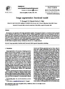
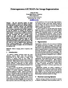
Three examples using the direct Potts segmentation will now be discussed using a photographic image, a medical image, and an acoustic seafloor image. Each segmentation result is compared to a histogram segmentation technique in which the image is partitioned into four uniformly distributed intensity ranges. The four-level histogram method is a very efficient, linear-time process but does not distinguish grainy regions from smooth regions. The photographic image in Fig. 5a[29] contains depictions of water, sky, vegetation, and rocks. Using step 1 of the direct Potts segmentation method as described in the previous section (with Q = 16 and st = 7.5), sky and rock are distinguished from water and vegetation according to pixel intensities. The sky and rock are represented as lighter shades, while water and vegetation are depicted as darker shades of gray in Figs. 5b and 5c. To further separate the shades of gray, step 2 in the previous section effectively identifies regions of different texture (smooth or grainy). The full (steps one and two) direct Potts segmentation result is shown in Fig. 5b. After filtering by using the despeckle algorithm, we see in Fig. 5c that the sky (white, bright/smooth texture) is distinguished from the rock regions (light gray, bright/grainy), and water (dark gray, dark/smooth) is distinguished from the vegetation (black, dark/grainy). Segmenting the image by intensity using the four-level histogram produces the image in Fig. 5d. The histogram approach does not distinguish sky from rock (both are light gray) and does comparatively less well in distinguishing vegetation (lower left of image) from the background. A comparison of Figs. 5c and 5d underscores the importance of considering both intensity and texture in image segmentation. Figure 6a[30] shows an MRI image of a brain with a tumor in the upper left quadrant. The segmented image using the direct Potts segmentation method with Q = 64 and st = 31.5 is shown in Fig. 6b. After filtering, we obtain the the image in Fig. 6c. Here, the white regions may be interpreted as possible tumorous tissue, light gray corresponds to matter at the periphery of the tumor, dark gray represents cerebrum, and black is other brain matter. Automated screening for tumors may be performed by finding white regions of significant size. Although, the four-level histogram method (Fig. 6d) also identifies a similar tumor region, the cerebrum is not distinguished from other brain matter. The affect of the chosen value for Q is demonstrated in Fig. 7. Larger values of Q result in more of the image being categorized as textured (represented as light and dark gray). Finally, acoustic seafloor images may be analyzed in real-time with the direct Potts segmentation method as demonstrated in Fig. 8. Here sand ripples are identified (in green) as a grainy texture and is separated from the remainder of the image. Rapid seafloor characterization enables effec-
5
(a)
(a)
(b)
(c)
(d)
(b)
(c)
(d)
FIG. 5: Grayscale photo (a) showing water, sky, vegetation, and rocks. Segmentation of image using the direct Potts method (b) with Q = 16 and st = 7.5. Image is from the Berkeley Segmentation Data Set. (See 23.) The image at lower left (c) is a 4-level direct Potts segmentation of (a) that has been despeckled. Here the sky, rock, vegetation, and water are represented as white, light gray, dark gray, and black regions, respectively. The image at lower right (d) is the segmented and despeckled image using the four-level histogram method applied to (a).
tive mine hunting/avoidance operations [7, 24, 25], by indicating where seafloor mines are likely to be buried (mud), partially buried (sand), or unburied (rock).
VII.
CONCLUSIONS
We have examined the direct application of the Potts model to grayscale image segmentation. The Potts model is applied to the grayscale image itself rather than its more common application to the segmented image. The result is a segmentation method which processes in lin-
FIG. 6: MRI of a tumorous brain at upper left (a). A tumor is seen as the bright spot in the upper left region of the MRI. This image is from the Iowa Neuroradiology Library. Image at upper right (b) is the direct Potts segmentation with Q = 64, st = 31.5. Lower left (c) is the direct Potts segmentation that has been despeckled. The clearly visible white segment identifies the tumor. A tumor is clearly visible as the bright spot in the upper left region. The periphery of the tumor is shown in light gray, while cerebrum is represented as dark gray. Other brain matter is shown in black. For comparison, lower right (d) is the despeckled four-level histogram segmentation, which identifies the tumor region, but cannot distinguish cerebrum from other brain matter.
ear time instead of the exponential or power-law time required with conventional Potts segmentation methods. This increase in computational efficiency is vital for realtime, high data volume, and high resolution applications. The method is analogous to minimizing the total energy in a two-dimensional magnetic spin glass where the energy is calculated according to four Potts models. Each of the four Potts models corresponds to a distinct type of magnetism, so the direct Potts segmentation method effectively distinguishes regions in the spin glass that most closely adhere to the properties of four classes of magnetism, namely ferromagnetism, antiferromagnetism, paramagnetism, and diamagnetism. In digi-
6
(a)
(b)
(c)
FIG. 7: Despeckled segmentation images of Fig. 6a using the direct Potts method are shown for different values for Q. Results are shown for Q = 16 (a), Q = 32 (b), and Q = 128. In each case, the intensity threshold is st = (Q − 1)/2. For higher values of Q, more of the image is categorized as textured (light and dark gray).
tal image segmentation, pixel intensities are substituted for the magnetic spins in the spin glass. The astute reader will note that no mention has been made of the physical basis for the coupling constants Jα for the regions in the segmented image. The origins of the image pixels’ couplings may, in fact, be complicated or unknown. Branching of plants give a textured appearance in Fig. 5a, while the distribution of blood vessels and other brain material likely gives the textured appearance to Fig. 6a. Underwater sand ripples may arise from the fluid dynamics and saltation [26, 27] at the seafloor. The direct Potts segmentation has the advantages of being unsupervised (no training sets needed), very efficient (linear-time, only a few operation per pixel), and effective for texture identification. For many image segmentation applications in which texture is important, this direct Potts method may be expected to produce better results than other lineartime methods.
Acknowledgments
FIG. 8: Acoustic image of the seafloor formed using a sidescan sonar system, which creates an image going out on either side via an acoustic time series. The direct Potts segmentation with Q = 16 and st = 7.5 separates the region containing sand ripples (in green) from the rest of the image. The ripples are identified as a textured region and is labeled as sand since neither mud nor rock are likely to exhibit ripples.
This work was supported by the Naval Research Laboratory’s Advanced Graduate Research Program. The author thanks the Tulane Center for Polymer Reaction Monitoring and Characterization (PolyRMC) for resources provided. A special thanks goes to Dr. Luca Celardo for helpful discussions. The views expressed in this article are those of the author and do not represent opinion or policy of the US Navy or Department of Defense.
[1] D. L. Pham, C. Xu, and J. L. Prince, “Current Methods in Medical Image Segmentation,” Annu. Rev. Biomed. Eng. 2, 315–337 (2000). [2] Y. H. Yang, M. J. Buckley, S. Dudoit, and T. P. Speed, “Comparison of Methods for Image Analysis on cDNA Microarray Data,” J. Comput. Graph. Stat. 11, 108–136 (2002). [3] S. Peng, B. Urbanc, L. Cruz, B. T. Hyman, and H. E.
Stanley, “Neuron recognition by parallel Potts segmentation,” Proc. Natl. Acad. Sci. USA 100, 3847–3852 (2003). [4] V. Grau, A. U. J. Mewes, and M. Alca˜ niz “Improved watershed transform for medical image segmentation using prior information,” IEEE Trans. Med. Imaging 23, 447–458 (2004). [5] S. Hadjidemetriou, C. Studholme, S. Mueller, M. Weiner, N. Schuff, “Restoration of MRI data for intensity non-
7
[6]
[7] [8]
[9] [10] [11] [12]
[13] [14]
[15] [16]
[17] [18]
uniformities using local high order intensity statistics,” Med. Image Anal. 13, 36–48 (2009). X. Descombes, M. Moctezuma, H. Maˆıtre, and J.-P. Rudant, “Coastline detection by a Markovian segmentation on SAR images,” Signal Process. 55, 123–132 (1996). F. W. Bentrem, W. E. Avera, and J. Sample, “Estimating surface sediments using multibeam sonar,” Sea Technol. 47, 37–40 (2006). T. Asano, D. Z. Chen, N. Katoh, and T. Tokuyama, “Efficient Algorithms for Optimization-based Image Segmentation,” Int. J. Comput. Geom. Ap. 11, 145–166 (2001). E. Ising, “Report on the theory of ferromagnetism,” Z. Phys. 31, 253–258 (1925). R. B. Potts, “Some Generalized Order-Disorder Transformations,” Proc. Camb. Philos. Soc. 48, 106–109 (1952). F. W. Bentrem, “4-Level Spin-Glass Image Segmentation with Energy Minimization,” Provisional Patent Application, Navy Case No. 99,755 (2009). K. Tanaka, “Statistical-mechanical approach to image processing,” J. Phys. A: Math. Gen. 35, R81–R150 (2002). J. P. Neirotti, S. M. Kurcbart, and N. Caticha, Phys. Rev. E 68, 031911 (2003). M. Blatt, S. Wiseman, and E. Domany, “Superparamagnetic Clustering of Data,” Phys. Rev. Lett. 76, 3251– 3254 (1996);“Data clustering using a model granular magnet,” Neural Computation 9, 1805–1842 (1997). S. Wiseman, M. Blatt, and E. Domany, “Superparamagnetic clustering of data,” Phys. Rev. E 57, 3767 (1998). K. Tanaka, H. Shouno, M. Okadak, and D. M. Titterington, “Accuracy of the Bethe approximation for hyperparameter estimation in probabilistic image processing,” J. Phys. A: Math. Gen. 37, 8675–8695 (2004). E. Sharon, A. Brandt, and R. Basriy, “Fast Multiscale Image Segmentation,” Comp. Vision Pattern Recognition, Proc. IEEE Conf. 1, 70–77 (2000). P. F. Felzenszwalb and D. P. Huttenlocher, “Efficient Graph-Based Image Segmentation,” Int. J. Comp. Vision
59, 167–181 (2004). [19] A. X. Falc˜ ao, P. A. V. Miranda, and A. Rocha, “A LinearTime Approach for Image Segmentation Using GraphCut Measures,” Lec. Notes Comp. Sci. 4179/2006, 138– 149 (2006). [20] D. Chandler, Introduction to Modern Statistical Mechanics (Oxford University Press, New York, 1987). [21] J. C. Lee Thermal Physics: Entropy and Free Energies (World Scientific Publishing Company, Singapore, 2002). [22] L. Onsager “Crystal statistics. I. A two-dimensional model with an order-disorder transition.” Phys. Rev. 65, 117–149 (1944). [23] D. Martin, C. Fowlkes, D. Tal, and J. Malik, A Database of Human Segmented Natural Images and its Application to Evaluating Segmentation Algorithms and Measuring Ecological Statistics. in Proceedings of the 8th International Conference on Computer Vision, 2001 (2001), Vol. 2, p. 416–423. [24] F. W. Bentrem, J. Sample, M. T. Kalcic, M. E. Duncan, High-frequency acoustic sediment classification in shallow water. in Proceedings of Oceans 2002 (MTS/IEEE, Biloxi, 2002), Vol. 1, p. 7–11. [25] F. W. Bentrem, J. T. Sample, and M. M. Harris, Computational Solutions for Today’s Navy. Scientific Computing 25, 30–32 (2008). [26] R. A. Bagnold The Physics of Blown Sand and Desert Dunes (Methuen, London, 1941). [27] L. Kang and L. Guo, Numerical simulation of aeolian sand ripples. Phys. Lett. A 330, 198–202 (2004). [28] ImageMagick Studio LLC, Landenberg, PA, USA [29] From the Berkeley Segmentation Data Set (http://www.eecs.berkeley.edu/Research/Projects/CS/∼vision/group Used with permission. [30] From the Iowa Neuroradiology Library (http://www.uiowa.edu/c064s01/index.html). Used with permission.