{For all node pairs (BNn, CNm), corresponding to Hmn = 1 in the parity check matrix H of the code do:}. 4: {Compute the message sent from CNm to BNn,.
Falc˜ ao G, Yamagiwa S, Silva V et al. Parallel LDPC decoding on GPUs using a stream-based computing approach. JOURNAL OF COMPUTER SCIENCE AND TECHNOLOGY 24(5): 913–924 Sept. 2009
Parallel LDPC Decoding on GPUs Using a Stream-Based Computing Approach Gabriel Falc˜ao1 , Student Member, IEEE, Shinichi Yamagiwa2 , Member, IEEE, Vitor Silva1 and Leonel Sousa2,3 , Member, ACM, Senior Member, IEEE 1
Department of Electrical and Computer Engineering, University of Coimbra, Instituto de Telecomunica¸c˜ oes Polo II - Universidade de Coimbra, 3030-290 Coimbra, Portugal
2
INESC-ID, Technical University of Lisbon, Rua Alves Redol n.9, 1000-029 Lisboa, Portugal
3
Department of Electrical and Computer Engineering, IST, Technical University of Lisbon, Rua Alves Redol n.9 1000-029 Lisboa, Portugal
E-mail: {gff, vitor}@co.it.pt; {yama, las}@inesc-id.pt Received July 8, 2008; revised May 20, 2009. Abstract Low-Density Parity-Check (LDPC) codes are powerful error correcting codes adopted by recent communication standards. LDPC decoders are based on belief propagation algorithms, which make use of a Tanner graph and very intensive message-passing computation, and usually require hardware-based dedicated solutions. With the exponential increase of the computational power of commodity graphics processing units (GPUs), new opportunities have arisen to develop general purpose processing on GPUs. This paper proposes the use of GPUs for implementing flexible and programmable LDPC decoders. A new stream-based approach is proposed, based on compact data structures to represent the Tanner graph. It is shown that such a challenging application for stream-based computing, because of irregular memory access patterns, memory bandwidth and recursive flow control constraints, can be efficiently implemented on GPUs. The proposal was experimentally evaluated by programming LDPC decoders on GPUs using the Caravela platform, a generic interface tool for managing the kernels’ execution regardless of the GPU manufacturer and operating system. Moreover, to relatively assess the obtained results, we have also implemented LDPC decoders on general purpose processors with Streaming Single Instruction Multiple Data (SIMD) Extensions. Experimental results show that the solution proposed here efficiently decodes several codewords simultaneously, reducing the processing time by one order of magnitude. Keywords data-parallel computing, graphics processing unit (GPU), Caravela, low-density parity-check (LDPC) code, error correcting code
1
Introduction
Low-Density Parity-Check (LDPC) codes were originally proposed by Robert Gallager in 1962[1] and rediscovered by Mackay and Neal in 1996[2] . They have been used in recent digital communication systems, such as DVB-S2, WiMAX and other emerging standards. LDPCs are linear (n, k) block codes[3] defined by parity check sparse binary H matrices with (n − k) rows and n columns of dimension. They are usually represented by bipartite or Tanner[4] graphs, formed by Bit Nodes (BNs) and Check Nodes (CNs) linked by bidirectional edges. LDPC decoding requires the propagation of messages between connected nodes, as indicated by the Tanner graph. It is based on the computationally intensive Sum-Product Algorithm (SPA), also called belief propagation.
This family of decoders presents computational challenges due to the irregularity of the algorithm operating over sparse matrices, or linked lists representing the irregular interconnection network between BNs and CNs according to the Tanner graph description[5] . They require complex control flow, such as nested loops representing recursive computation. Therefore, the only available solutions for real-time processing are hardware-based Application Specific Integrated Circuits (ASIC) that usually adopt integer arithmetic[6] . But hardware only provides non-flexible and nonscalable dedicated solutions[7−9] that involve long development times and expensive non-recurring engineering. More flexible solutions for LDPC decoding using specialized Digital Signal Processors have recently been proposed[10] . In recent years, multi-core architectures have
Regular Paper This work was partially supported by the Portuguese Foundation for Science and Technology, through the FEDER program, and also under Grant No. SFRH/BD/37495/2007.
914
evolved from dual or quad-core to tera-scale systems, supporting multi-threading, a powerful technique to hide memory latency, while at the same time provide larger SIMD units for vector processing[11] . Programmed under the stream-based model, recent GPUs are multicore architectures that can also be used for general purpose processing (GPGPU)[12] , yielding a high level of performance in commodity products[13−14] . The literature contains publications about GPGPU applications that include i) numerical computations, such as dense and sparse matrix multiplications[15−16] , ii) computer graphics algorithms, such as those in ray tracing processing[17] , iii) demanding simulations applied to physics such as fluid mechanics solvers[18] , and iv) database and data mining operations[19−20] . At the programming level, Buck et al. propose extensions to the C language known as Brook[21] , which facilitate the programming of general purpose computation on GPUs. Brook supports data-parallel constructs and enables the use of GPUs as streaming co-processors. However, to apply GPUs for general purpose processing, there is still the need to manage and control GPU’s operations. Among the programming tools and environments developed for GPGPU are the Compute Unified Device Architecture (CUDA) from NVIDIA[22] , and the Caravela platform[23−24] . While CUDA is a very effective specific solution to improve efficiency but only on Tesla-based NVIDIA GPUs, the Caravela tool is a general programming interface, based on a streambased computing model that can use any GPU as coprocessor. Caravela does not directly interact with the GPU hardware, but rather communicates with the GPU driver, which makes it a generic and powerful programming interface tool that operates independently of the operating system and GPU manufacturer. The main purpose of Caravela is to make it possible to develop and test parallel algorithms for GPUs and not to compete performance-wise with commercial dedicated and optimized programming tools like CUDA. The execution unit of the Caravela platform is defined as a flow-model and can be programmed in DirectX[25] or OpenGL[26] . This paper proposes a novel approach for streambased LDPC decoding based on the computationally intensive SPA. It exploits data-level parallelism according to the stream-based computing model. An efficient parallel algorithm was developed for LDPC decoding on GPUs and programmed using the Caravela programming interface and tools. Experimental results show that the proposed algorithm can run significantly faster on GPUs than on modern general purpose processors. Efficient solutions were developed in order to compare an LDPC decoder executing on a CPU against a novel approach on a GPU
J. Comput. Sci. & Technol., Sept. 2009, Vol.24, No.5
that conveniently exploits the parallelism of streambased architectures, by simultaneously decoding several codewords. Although this paper is about LDPC decoding, because this is the operation that demands most computational power, it is still possible to implement LDPC coding on GPUs. The main contributions of this paper that implements an efficient parallel LDPC decoder on GPUs are: i) the development of novel data structures for LDPC decoding that support stream-based computing; this new approach uses different compact data structures from the conventional compress row storage and compress column storage formats[16] , where connections between the nodes of the Tanner graph are represented using circular addressing, which facilitates simultaneous access to different data elements as required by SPA processing; ii) the introduction of the new concept of multi-codeword decoding (the parallel architecture of the GPU allows decoding in simultaneous several codewords); iii) an architecture that represents a programmable solution, as opposed to VLSI-dedicated LDPC decoders (new trends show that the number of cores on a processor is rising, and computational performance should increase over the next few years); iv) the use of floating-point arithmetic with 32-bit data precision (single-precision), which produces a lower Bit Error Rate (BER), compared with the typical 5 to 6-bit data precision and fixed-point arithmetic used in VLSIbased solutions. This paper is organized as follows. Section 2 analyzes the Sum-Product Algorithm (SPA) used for LDPC decoding and the respective data dependencies. A new algorithm and data structures suitable for stream-based LDPC decoding are proposed in Section 3. Section 4 describes the GPU architecture and the Caravela interface programming tool, while Section 5 contains the experimental evaluation, comparing execution times on GPUs and general purpose CPUs. Section 6 concludes the paper. 2
Sum-Product Algorithm for LDPC Decoding
Considering a set of bits, or codeword, that we wish to transmit over a noisy channel, the theory of graphs applied to error correcting codes has fostered codes to performances extremely close to the Shannon limit[27] . The certainty of an information bit can be spread over several bits of a codeword, allowing, in certain circumstances, to recover the correct codeword on the decoder side, in the presence of noise. 2.1
Sum-Product Algorithm
In a graph representing a linear block error correcting code, reasoning algorithms exploit
Gabriel Falc˜ ao et al.: Parallel LDPC Decoding on GPUs
probabilistic relationships between nodes imposed by parity-check equations. The SPA belongs to this category of algorithms. It finds a set of maximum a posteriori probabilities (MAP)[28] , which allows the most likely transmitted codeword to be inferred. Given an (n, k) binary LDPC code, we assume BPSK modulation which maps a codeword c = (c0 , c1 , c2 , . . . , cn−1 ) into a sequence x = (x0 , x1 , x2 , . . . , xn−1 ), according to xi = (−1)ci . Then, x is transmitted through an Additive White Gaussian Noise (AWGN) channel, producing a received sequence y = (y0 , y1 , y2 , . . . , yn−1 ) with yi = xi + ni , where ni represents AWGN with zero mean and variance σ 2 .
915
(Kernel 1 — Horizontal Processing) 1 1 (i−1) (i) rmn (0) = + (1 − 2qn0 m (1)), 2 2 n0 ∈N (m)\n {z } |
Π
π(·) (i)
(i)
rmn (1) = 1 − rmn (0),
5:
(2)
{where N (m)\n represents BN’s connected to CN m excluding BN n .} {Compute message from BN n to CN m :} (Kernel 2 — Vertical Processing)
Π
(i)
(i) qnm (0) = knm (1 − pn ) 0 rm0 n (0), m ∈M (n)\m {z } |
(3)
λ(·)
Algorithm 1. SPA
Π
(i)
qnm (1) = knm pn
1: {Initialization} (0)
(1)
(0)
pn = p(yi = 1); qmn (0) = 1 − pn ; qmn (1) = pn ;
(i)
rm0 n (1),
(4) (i)
T
2: while (ˆ cH 6= 0 ∧ i < I) {ˆ c-decoded word; IMax no. of iterations. } do 3: {For all node pairs (BN n , CN m ), corresponding to H mn = 1 in the parity check matrix H of the code do:} 4: {Compute the message sent from CN m to BN n , that indicates the probability of BN n being 0 or 1:}
m0 ∈M (n)\m
6:
{where knm are chosen to ensure qnm (0) + (i) qnm (1) = 1, and M (n)\m is the set of CN’s connected to BN n excluding CN m .} {Compute the a posteriori pseudo-probabilities:} (i)
(i) Qn (1)
=
Π
(i) rmn (0), m∈M (n) (i) kn pn rmn (1), m∈M (n)
Qn (0) = kn (1 − pn )
Π
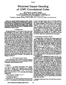
Fig.1. Example of the Tanner graph and some messages being exchanged between CN m and BN n nodes.
916
J. Comput. Sci. & Technol., Sept. 2009, Vol.24, No.5 (i)
7:
{where kn are chosen to guarantee Qn (0) + (i) Qn (1) = 1.} {Perform hard decoding:} ∀n, ( (i) 1 ⇐ Qn (1) > 0.5, (i) cˆn = (5) (i) 0 ⇐ Qn (1) < 0.5,
8: end while
The SPA applied to LDPC decoding is illustrated in Algorithm 1. It is mainly described by two different horizontal and vertical intensive processing blocks, defined by (1)∼(2), and (3)∼(4), respectively. (1) and (2) update the messages from CN m to BN n , considering accesses to H in a row-major basis — horizontal processing — indicating the probability of BN n being 0 or 1. Similarly, the latter pair of (3) and (4), (i) computes the qnm messages sent from BN n to CN m , assuming accesses to H in a column-major basis — vertical processing. Finally, (5) performs the hard decoding at the end of an iteration. The iterative procedure is ˆ verifies all parity-check stopped if the decoded word c equations (ˆ cH T = 0), or if the maximum number of iterations (I) is reached. Fig.1 shows an example for a 4 × 8 H matrix representing 8 BNs and 4 CNs. BN 0 , BN 1 and BN 2 are updated by CN 0 as indicated in the first row of H. From the second until the last row it can be seen that the subsequent BNs are updated by the CNs connected to them. For each iteration and for every BN, the cor(i) (i−1) responding qnm data is read and rmn messages are updated in iteration i according to (1) and (2). Table 1. Number of Arithmetic Operations Involved in the Update of Messages for the Horizontal and Vertical Processing Steps per Iteration, Using the SPA for LDPC Decoding SPA Horizontal processing Vertical processing
+
∗
v(v + 1)M tN
2v(v − 1)M 2t2 N
Given an H matrix with M rows (CNs) and N columns (BNs), a mean row weight v and a mean column weight t, with v, t > 2, Table 1 gives the computational complexity in terms of the number of floatingpoint add and multiply operations required for both the horizontal and vertical processing steps in the SPA LDPC decoding algorithm. Depending on the application and on the channel conditions (typically, the most important is Signal-to-Noise Ratio), LDPC decoding can imply a substantial number of arithmetic operations per second, which justifies the investigation of new parallelization strategies. 2.2
Parallelizing Message Computations
The Mv messages in the left column of Table 2, for the example in Fig.1, show no data dependency constraints in the message updating procedure for the horizontal step (the π(·) function can be found in Algorithm 1, while miZ0 →W0 means message m circulating from node Z0 to node W0 during iteration i). These operations can be parallelized by adopting a convenient scheduling that supports the updating of different messages for different vertices, simultaneously for different parts of the graph. The flooding schedule [3] algorithm adopted in this work guarantees that no CN is updated before all BNs conclude their updating procedure and vice versa. The messages sent by BNs are all updated together before CN messages start being updated. On each iteration, all data used for computing a new message was obtained in the previous iteration. This principle is fundamental when developing a parallel SPA LDPC decoder to suit a parallel architecture (e.g., a GPU), as described in Section 3. A similar conclusion can be drawn when analyzing the vertical processing in the right-hand column of Table 2 (the λ(·) function can be found in Algorithm 1). In spite of the irregular memory access pattern, here, the processing of tN new messages can also be parallelized.
Table 2. SPA Parallelization of Message Computations for the Example in Fig.1 Horizontal Kernel
Vertical Kernel
i−1 miCN 0 →BN0 = π(mi−1 BN 1 →CN0 , mBN 2 →CN0 )
i−1 miBN 0 →CN0 = λ(p0 , mCN ) 2 →BN0
i−1 π(mi−1 BN 0 →CN0 , mBN 1 →CN0 ) i−1 π(mBN 4 →CN1 , mi−1 BN 5 →CN1 ) i−1 π(mi−1 BN 3 →CN1 , mBN 5 →CN1 ) i−1 π(mBN 3 →CN1 , mi−1 BN 4 →CN1 ) i−1 π(mi−1 BN 3 →CN2 , mBN 6 →CN2 ) i−1 π(mBN 0 →CN2 , mi−1 BN 6 →CN2 ) i−1 π(mi−1 BN 0 →CN2 , mBN 3 →CN2 ) i−1 π(mBN 4 →CN3 , mi−1 BN 7 →CN3 ) i−1 π(mi−1 , m BN 1 →CN3 BN 7 →CN3 ) i−1 i−1 π(mBN 1 →CN3 , mBN 4 →CN3 )
i−1 miBN 1 →CN0 = λ(p1 , mCN ) 3 →BN1
i−1 miCN 0 →BN1 = π(mi−1 BN 0 →CN0 , mBN 2 →CN0 )
miCN 0 →BN2 miCN 1 →BN3 miCN 1 →BN4 miCN 1 →BN5 miCN 2 →BN0 miCN 2 →BN3 miCN 2 →BN6 miCN 3 →BN1 miCN 3 →BN4 miCN 3 →BN7
= = = = = = = = = =
miBN 0 →CN2 = λ(p0 , mi−1 CN 0 →BN0 ) i−1 miBN 1 →CN3 = λ(p1 , mCN ) 0 →BN1
miBN 2 →CN0 = λ(p2 )
miBN 3 →CN1 = λ(p3 , mi−1 CN 2 →BN3 ) i−1 miBN 3 →CN2 = λ(p3 , mCN ) 1 →BN3 i−1 miBN 4 →CN1 = λ(p4 , mCN ) 3 →BN4 i−1 miBN 4 →CN3 = λ(p4 , mCN ) 1 →BN4
miBN 5 →CN1 = λ(p5 ) miBN 6 →CN2 = λ(p6 )
miBN 7 →CN3 = λ(p7 )
Gabriel Falc˜ ao et al.: Parallel LDPC Decoding on GPUs
To illustrate these concepts for the horizontal processing, the first row of H in Fig.2(a) shows that the three messages associated with the first CN equation can be updated in parallel without any kind of conflict between nodes (maintaining data consistency). The other messages on the left side of Table 2 show that the same principle applies to the other CN equations in the example illustrated in Fig.1. Again, a similar conclusion can be drawn for the vertical processing. Messages miBN 0 →CN0 and miBN 0 →CN2 (in the right column of Table 2) represent the update of the two messages associated with BN 0 , as defined by the first column of H. Fig.2(b) shows that data dependencies also support parallel operations in this case. 3
Stream-Based LDPC Decoding
(1)∼(4) in Algorithm 1 are the most intensive calculations in SPA. To take advantage of the very high processing performance of GPUs to compute them, efficient data structures adapted for stream computing are necessary. A stream-based LDPC decoder needs different computation and memory access patterns in consecutive kernels to update BNs and CNs, respectively. In order to support the execution of kernels 1 and 2 (representing horizontal and vertical processing in Algorithm 1) on the GPU, we propose two stream-based data structures H BN and H CN to represent the H matrix. These structures require significantly less memory and are suitable for stream computing both regular and irregular codes.
917
transformation performed in H to produce the compact stream data structures. H BN codes information about edge connections used in each parity check equation (horizontal processing). This data structure is generated by scanning the H matrix in a row major order and by sequentially mapping only the BN edges associated with non-null elements in H used by a single CN equation (in the same row). Algorithm 2 details this procedure. In step 5, it can be seen that all edges associated with the same CN are collected and stored in consecutive positions inside H BN . The addressing in each row of H becomes circular. The pixel element corresponding to the last non-null element of each row points to the first element of this row, implementing a circular list that is used to update all the π(·) messages. The circular addressing allows to introduce a high level Algorithm 2. Generating Compact H BN from Original H matrix 1: {Read a binary M × N matrix H} 2: 3: 4:
for all CN m (rows in H mn ): do for all BN n (columns in H mn ): do if H mn == 1 then
5:
ptr next = j : H mj == 1, with n + 1 6 j < (n + N ) mod N ; {Find circularly the right neighbor on the current row} H BN = ptr next ;
6:
{Store ptr next into the H BN structure, using a square texture of dimension »s M N ¼ P P D × D, with D = H mn } m=1 n=1
3.1
Mapping the Tanner Graph into Data Streams
Let us use the example in Fig.1 to illustrate the
7: 8: 9:
end if end for end for
Fig.2. Memory accesses defined by the Tanner graph for the example shown in Fig.1. (a) For horizontal neighbors. (b) For vertical neighbors. Messages being read/written are the non-zero elements emphasized in colors.
918
of parallelism. In the limit, for a multi-processor platform, a different pixel processor can be allocated to every single edge or π(·) message. Each element of the data structure, here represented by a pixel texture, records the address of the next entry pointer and the corresponding value of rmn . Although the pixel elements in Fig.3 are represented by their row and column addresses, the structures can be easily vectorized by convenient 1D or 2D reshaping according to the target stream-based architecture they apply to. The 3D representation shows that the same matrix information can be used to simultaneously decode several codewords, by applying SIMD processing, for example. In the upper left corner of Fig.3, it can be seen that the pixel processor allocated to compute the message miCN 0 →BN 0 (identified as message r0,0 ) depends i−1 on messages mi−1 BN 1 →CN 0 and mBN 2 →CN 0 coming from BN 1 and BN 2 . This is equivalent to saying that to update BN 0 (upper left pixel), we have to read the information from BN 1 (BN 0 holds the address of BN 1 ) and BN 2 (BN 1 holds the address of BN 2 ) circularly, and then update BN 0 (BN 2 knows the address of BN 0 ). This mechanism is used to update all the other BNs in parallel. For the vertical processing, H CN is a sequential representation of the edges associated with non-null elements in H connecting every BN to all its neighboring CNs (in the same column). This data structure is generated by scanning the H matrix in a column
J. Comput. Sci. & Technol., Sept. 2009, Vol.24, No.5
major order. Once again, the access between adjacent elements is circular, as described in Algorithm 3 and illustrated in Fig.4 for the H matrix given in Fig.1. In this case, a careful construction of the 2D addresses in H CN is Algorithm 3. Generating Compact H CN from original H matrix and H BN 1: {Read a binary M × N matrix H 2:
for all BN n (columns in H mn ): do
3:
for all CN m (rows in H mn ): do
4:
if H mn == 1 then
5:
6:
ptr tmp = i : H in == 1, with m + 1 6 i < (m + M ) mod M ; {Find circularly the neighbor below on the current column} ptr next = search(H BN , ptr tmp , n);
7:
{Find in H BN the pixel with indices (ptr tmp , n)} H CN = ptr next ; {Store ptr next into the H CN structure, with addresses compatible with H BN , using a square texture of dimension »s M N ¼ P P D × D, with D = H mn } m=1 n=1
8: 9: 10:
end if end for end for
Fig.3. H BN structure. A 2D texture representing bit node edges with circular addressing for the example in Fig.1. Also, the pixel processors entry points are shown.
Gabriel Falc˜ ao et al.: Parallel LDPC Decoding on GPUs
919
Fig.4. H CN structure. A 2D texture representing check node edges with circular addressing for the example in Fig.1. Also, the pixel processors entry points are shown.
required, because every pixel texture representing a graph edge must be in exactly the same position as it is in H BN . This meticulous positioning of the pixel elements in H CN allows the processing to be performed alternately for both kernels, using the same input textures. Step 6 shows that ptr next is placed in the same pixel texture (or n, m edge) that it occupies in H BN .
units, and also concurrent calculations for the resulting output data streams.
Fig.4 describes how the H CN data structure is organized for the example in Fig.1, under kernel 2. The message miBN 0 →CN0 (identified as message q0,0 ) is a function of p0 , mi−1 CN 2 →BN 0 and should update the upper left pixel representing CN 0 , which holds the address of CN 2 . This is another way of saying that CN 2 updates CN 0 , and vice-versa. This mechanism works in the same way for all the other CNs in the grid. 4
LDPC Decoding on GPUs with Caravela
On a GPU, the color data is written into the frame buffer, which outputs it to the screen as depicted in Fig.5. Vertex/pixel processors compute four floatingpoint values (XYZW for vertex, ARGB for pixel) in parallel. Moreover, the coloring operation in the pixel processor is also parallelized because the output colors are generated independently as data streams, and each element of a stream is also independently processed. Recent GPUs therefore include several pixel processor cores that generate output colors concurrently. These processors perform SIMD computation in four data
Fig.5. Processing steps for graphics rendering on a GPU.
In recent GPUs, vertex and pixel processors are programmable. These processors are usually programmed for graphics purposes. It is very important that the programs run fast so that complex frames can be generated in real-time. GPUs have dedicated floating-point processing pipelines in these processors enabling them to achieve realistic graphics scenes with high resolution in real-time, and GPGPU applications can make use of such high performance processors. However, the rasterizer is composed of fixed hardware, and its output data cannot be programmed. Moreover, in almost
920
J. Comput. Sci. & Technol., Sept. 2009, Vol.24, No.5
all GPUs the output data from the rasterizer is just sent to the pixel processor and cannot be fetched by the CPU. Thus, only the computing power of the pixel processor is used in traditional GPUs for GPGPU applications, because of both its programmability and its flexibility for I/O data control① . These processors can be programmed in standard languages such as the DirectX Assembly Language, the High Level Shader Language (HLSL)[25] and the OpenGL Shading Language[26] . The programs are called shader programs. 4.1
following definitions of the processing units: Machine is a host machine, Adapter is a video adapter that includes one or more GPUs and, finally, Shader is a GPU. An application needs to map a flow-model into a shader, before executing the mapped flow-model.
Caravela Platform
For GPGPU, programmers need specific knowledge for controlling GPU hardware via a graphics runtime environment. Moreover, there are different runtime environments, depending on the GPU vendor and the programming language. This is an overhead for programmers who have to concentrate their best efforts on implementing efficient parallel algorithms in a shader program. To solve this disparity in programming GPUbased applications, the Caravela platform[23] has been implemented for GPGPU, and is publicly available at the web site[24] . The execution unit of the Caravela platform is based on the flow-model. As Fig.6 shows, the flow-model is composed of input/output data streams, constant parameter inputs and a pixel shader program or kernel, which fetches the input data streams and processes them to generate the output data streams. The application program in Caravela is executed as streambased computation, like a dataflow processor. However, the input data stream of the flow-model can be accessed randomly, because the input data streams are just memory buffers for the program that uses the data. On the other hand, the output data streams are sequences of data elements. The designation “pixel” for a unit of the I/O buffer is used because the pixel processor processes input data for every pixel color. A flow-model unit has defined the number of pixels for the I/O data streams, the number of constant parameters, the data type of the I/O data streams, the pixel shader program and the requirements for the GPU targeted. To give portability to the flow-model, these items are packed into an eXtensible Markup Language (XML) file. This mechanism allows the usage of a flow-model unit located in a remote computer, just by fetching the XML file. The Caravela platform mainly consists of a library that supports an Application Programming Interface for GPGPU. The Caravela library has adopted the
Fig.6. Structure of the flow-model.
The Caravela runtime operates as a resource manager for flow-models. By using the Caravela library functions, programmers can easily implement target applications in the framework of flow-models, by just mapping flow-models into shader(s). Therefore, programmers do not need to know much about graphics runtime environment details or GPU architectures, which means that the Caravela library can become an effective solution to tackle the problem of differences between graphical environments[24] . The execution of the flow-model covers both nonrecursive and recursive applications. Caravela optimizes buffer management, particularly for OpenGL, where an extension to the Caravela library was implemented[29] , allowing the efficient reutilization of output buffers as input data in future iterations. This optimization does not represent an overhead in computation time, as it simply swaps data pointers. It does not move blocks of data. 4.2
SPA Implementation Based on the Flow-Model
We developed a flow-model to support the LDPC decoder based on the Caravela tools, which also utilizes the efficient mechanisms provided for recursive computation. The synchronous data flow graph in Fig.7 represents the implemented stream-based LDPC decoder.
① There are some exceptions, namely the most recent NVIDIA GPU cards, where unified shaders can be allocated dynamically.
Gabriel Falc˜ ao et al.: Parallel LDPC Decoding on GPUs
Constants k1 and k2 represent the matrix sizes. According to Algorithm 1, for iteration 0 kernel 1 receives as inputs data stream p0 , a constant k1 and the stream H BN . The output stream r0 is then produced and it becomes one of the input data streams of kernel 2. The other inputs of this kernel are H CN and constant k2 . The processing iterates alternately over kernel 1 and kernel 2 until the last kernel 2 produces the final output stream qi−1 for iteration i − 1.
Fig.7. Synchronous data flow graph for a stream-based LDPC decoder: the pair kernel 1 and kernel 2 is repeated i times for an LDPC decoder executing i iterations.
921
flow-model unit that executes kernel 2. Data streams can be multiplexed through a simple and efficient swapping mechanism[29] . The output data stream can be feedback as an input stream of the next flow-model unit execution, and the process is repeated for each iteration. At the end, the last output stream conveys the decoded codeword. 5
Performance Evaluation
The proposed algorithm was programmed in recent CPUs and GPUs in order to evaluate the performance of the described stream-based LDPC decoder. Moreover, we also optimized the CPU program by hand, using the second generation of Stream SIMD Extensions (SSE2) of the IA-32 instruction set. The relative performance of CPU- and GPU-based approaches are compared for different workloads (i.e., H matrices with distinct characteristics). The experimental setup is presented in Table 3. It includes a recent 8800 GTX GPU from NVIDIA, with stream processors (SPs) running at 1.35 GHz and a modern Core 2 Duo processor from Intel at 2.4 GHz. The LDPC decoders are programmed on the CPU using the C language, version 8.0 of the MS V. Studio 2005 C/C++ compiler with the -O2 full optimization for speed, and on the GPU using version 2.0 of the OpenGL Shading Language and the Caravela library. Table 3. Experimental Setup
Platform Clock frequency Memory Language
Fig.8. Organization of the LDPC decoder flow-model.
Fig.8 graphically represents the corresponding flowmodel unit containing a shader program that supports the stream-based computation of both kernels, where the input and output data streams are 2D textures. In the first iteration, the input data stream 0 represents data channel probabilities. The first output stream is produced by performing kernel 1. After the first execution, this stream directly feeds the input of the next
CPU
GPU
Intel Core 2 Duo 2.4 GHz 1 GB C
NVIDIA 8800 GTX 1.35 GHz (p/SP) 768 MB OpenGL (GLSL)
The experiments were carried out in both platforms using five matrices of different sizes and with varying number of edges. They are represented by matrices A to E shown in Table 4. Their properties were chosen to approximately simulate the computational workload of LDPC codes with typical sizes ranging from small to medium and large (all sizes covered) and used in recent communication standards. These matrices are representative of a class of good codes which were downloaded from David J.C. MacKay’s website[30] . The decoder addresses only non-null elements in the H matrix by using structures to represent the edges similar to the ones described in Section 3. The LDPC decoder on the x86 CPU is based on efficient linked lists data structures, and both CPU and GPU solutions use single precision floating-point arithmetic.
② These are the pixels showing empty coordinates (×, ×) in Figs. 3 and 4, imposed by the GPU Caravela interface that only supports 2D data textures with square dimensions D × D, where D is a power of 2.
922
J. Comput. Sci. & Technol., Sept. 2009, Vol.24, No.5
Table 4. Matrices Under Test Matrix A B C D E
Size
Edges Edges/
111 × 999 2 997 408 × 816 4 080 212 × 1908 7 632 2448 × 4896 14 688 2000 × 4000 16 000
Texture
Row
Dim.
Unused Pixel Textures②
27 10 36 6 8
64 × 64 64 × 64 128 × 128 128 × 128 128 × 128
1 099 16 8 752 1 696 384
The pixel processors of the GPU were used with data inputted as textures and the output data stream assuming the usual place of the pixel color components’ output in a graphical application. However, all the details are hidden from the programmer by using the Caravela interface tool. To compute the SPA on the GPU, the input H matrix is placed into an input stream and kernel 1 and kernel 2 are processed in pixel processors, according to Fig.7. The proposed compact representation also allows the reduction of data transfers between the host memory (RAM) and the device VRAM, which is a very important aspect in the achievement of high performance with GPUs. 5.1
MMX registers from Intel CPUs, four floating-point elements are packed and operated together in a single instruction. The experimental results in Fig.10 show the processing times for the GPU and the CPU hand optimized with SSE2 instructions. The GPU needs significantly shorter decoding times to complete the processing. The speedup shown in Fig.9 increases as the number of edges being processed also increases, but not necessarily just depending on it. Comparing matrix A with matrix B, it can be seen that even though the latter has fewer unused pixel textures that represent no edges in the Tanner graph, the former performs faster because it has more edges per row (27 against 10). This is explained by the fact that GPUs perform better for algorithms demanding intensive computation. If we compare the above matrix A with matrix C, the latter performs with a speedup approximately 33% better, which seems to be consistent with the fact that it has around 33% more edges per row (36 against 27). Finally, matrix E has a better speedup than matrix D, depicted next to it, because the former has 8 edges per row while the latter has 6, and, at the same time, there is less dummy processing on unused pixel textures.
Experiments and Results
The purpose of Fig.9 is to assess the relative performance of the GPU and the CPU. The speedups show that, for the best case obtained with matrix C, the GPU is nearly 8 times faster than the CPU. In average, for the matrices under test, the execution speed is 3.5 times faster on the GPU when executing 50 iterations. For 100 iterations the average speedup rises to 4.3.
Fig.10. Decoding processing times for an 8800 GTX GPU from NVIDIA vs. an Intel CPU using SSE2.
Fig.9.
Global speedup comparison between CPU- and GPU-
based versions.
For a given Tanner graph, it is possible to decode 4z codewords in parallel, with z ∈ N, which allows the direct application of SIMD processing based on the use of Arithmetic Packed Instructions. In the present case, this optimization is made possible by performing the same arithmetic operation to decode four codewords simultaneously. Using xmm0-xmm7 128-bit
The experimental results in Fig.10 show that the CPU performance achieved when SSE2 instructions are used for LDPC decoding starts degrading after a certain dimension of H, mainly due to cache misses. On the other hand, when analyzing the GPU response, it is possible to conclude that the GPU performs better for large matrices. All in all, the GPU-based approach shows higher speedups for the LDPC decoding algorithm with intensive computation on huge quantities of data, due to its parallelism features and impressive processing power.
Gabriel Falc˜ ao et al.: Parallel LDPC Decoding on GPUs
923
Even using SSE2 instructions on the CPU, the GPU provides significantly shorter execution times, as depicted in Fig.10. The gain exists for 50 or more iterations in all tested matrices.
stream-based LDPC decoder approach leads to significant speedups, close to one order of magnitude, regarding to the processing time on modern general purpose processors.
5.2
References
Discussion
In order to achieve real-time processing, LDPC decoders usually have to be implemented in hardware. Reconfigurable FPGA architectures or ASICs usually implement LDPC decoding algorithms based on integer arithmetic[6] . The nature of LDPC codes demands huge workloads and a complex routing mechanism to support the message passing procedure between adjacent nodes. Some interesting solutions in the literature tackle such problems quite efficiently. Quaglio et al. propose a solution[5] for the irregular network connecting BNs and CNs according to the Tanner graph. A complete coder/decoder low-power solution based on VLSI is presented in [7], while reconfigurable solutions based on FPGAs are proposed in [8–9]. However, these implementations have reduced flexibility and use high non-recurring engineering. The massive dissemination of low-cost commodity programmable parallel devices such as GPUs has allowed us to develop a new flexible solution to the LDPC decoding problem. Furthermore, this solution supports floating-point arithmetic, which can provide a lower BER regarding hardware dedicated architectures. Although recent GPUs allow to obtain medium throughputs for LDPC decoding in real-time, a significant increase of GPU performance can be expected in the next few years, as more cores are being placed on a single device. The throughputs of the next generation of GPU-based LDPC decoders are likely to rise significantly. 6
Conclusions
This paper proposes a novel LDPC decoding approach suitable for the stream-based computing model, using GPU computational power to replace the conventional hardware solution. To pursue this goal, we developed compact and efficient stream-based data structures for the I/O data streams that fit the Tanner graph representation of an LDPC code. The Sum-Product Algorithm used for LDPC decoding was first tuned manually and programmed on CPUs using the second generation of Stream SIMD Extensions of the IA-32 instruction set. The algorithm was also written in OpenGL shader language, after which we applied the flow-model in the Caravela platform to program the LDPC decoder on GPUs and perform relative performance evaluation. The experimental results obtained for the GPU-based LDPC decoder allow us to state that the proposed
[1] Gallager R G. Low-density parity-check codes. IRE Transactions on Information Theory, 1962, 8(1): 21–28. [2] Mackay D J C, Neal R M. Near Shannon limit performance of low density parity check codes. IEE Electronics Letters, 1996, 32(18): 1645–1646. [3] Lin S, Costello D J. Error Control Coding. 2nd Ed., Prentice Hall, 2004. [4] Tanner R. A recursive approach to low complexity codes. IEEE Transactions on Information Theory, 1981, 27(5): 533– 547. [5] Quaglio F, Vacca F, Castellano C, Tarable A, Masera G. Interconnection framework for high-throughput, flexible LDPC decoders. In Proc. Design, Automation and Test in Europe (DATE2006), Munich, Germany, March 6–10, 2006, pp.124– 129. [6] Ping L, Leung W K. Decoding low density parity check codes with finite quantization bits. IEEE Communications Letters, 2000, 4(2): 62–64. [7] Zhang T, Parhi K. Joint (3, k)-regular LDPC code and decoder/encoder design. IEEE Transactions on Signal Processing, 2004, 52(4): 1065–1079. [8] Verdier F, Declercq D. A low-cost parallel scalable FPGA architecture for regular and irregular LDPC decoding. IEEE Transactions on Communications, 2006, 54(7): 1215–1223. [9] Falc˜ ao G, Gomes M, Gon¸calves J, Faia P, Silva V. HDL library of processing units for an automatic LDPC decoder design. In Proc. IEEE Ph.D. Research in Microelectronics and Electronics (PRIME), Otranto, Italy, June 11–16, 2006, pp.349–352. [10] Gomes M, Silva V, Neves C, Marques R. Serial LDPC decoding on a SIMD DSP using horizontal-scheduling. In Proc. 14th European Signal Processing Conference (EUSIPCO2006), Florence, Italy, Sept. 4–8, 2006. [11] Ghuloum A, Sprangle E, Fang J, Wu G, Zhou X. Ct: A flexible parallel programming model for tera-scale architectures. Intel, 2007, pp.1–21. [12] Owens J D, Luebke D, Govindaraju N, Harris M, Kruger J, Lefohn A E, Purcell T J. A survey of general-purpose computation on graphics hardware. Computer Graphics Forum, 2007, 26(1): 80–113. [13] Goodnight N, Wang R, Humphreys G. Computation on programmable graphics hardware. IEEE Computer Graphics and Applications, 2005, 25(5): 12–15. [14] Fok K L, Wong T T, Wong M L. Evolutionary computing on consumer graphics hardware. IEEE Intelligent Systems, 2007, 22(2): 69–78. [15] Kruger J, Westermann R. Linear algebra operators for GPU implementation of numerical algorithms. ACM Transactions on Graphics, 2003, 22(3): 908–916. [16] Bolz J, Farmer I, Grinspun E, Schroder P. Sparse matrix solvers on the GPU: Conjugate gradients and multigrid. ACM Transactions on Graphics, 2003, 22(3): 917–924. [17] Purcell T J, Buck I, Mark W R, Hanrahan P. Ray tracing on programmable graphics hardware. ACM Transactions on Graphics, 2002, 21(3): 703–712. [18] Harris M. Fast Fluid Dynamics Simulation on the GPU. GPU Gems, Fernando R. (ed.), Addison Wesley, 2004. [19] Govindaraju N K, Lloyd B, Wang W, Lin M, Manocha D. Fast computation of database operations using graphics
924
[20]
[21]
[22] [23]
[24] [25] [26] [27]
[28] [29]
[30]
processors. In Proc. the 2004 ACM SIGMOD International Conference on Management of Data, Paris, France, June 13– 18, 2004, pp.215–226. Govindaraju N K, Raghuvanshi N, Manocha D. Fast and approximate stream mining of quantiles and frequencies using graphics processors. In Proc. the 2005 ACM SIGMOD International Conference on Management of Data, Baltimore, USA, June 14–16, 2005, pp.611–622. Buck I, Foley T, Horn D, Sugerman J, Fatahalian K, Houston M, Hanrahan P. Brook for GPUs: Stream computing on graphics hardware. ACM Trans. Graph., 2004, 23(3): 777– 786. CUDA. Aug. 2007, http://developer.nvidia.com/object/cuda. html. Yamagiwa S, Sousa L. Caravela: A novel stream-based distributed computing environment. IEEE Computer, 2007, 40(5): 70–77. Caravela. April 2007, http://www.caravela-gpu.org. DirectX. April 2007, http://www.microsoft.com/directx. Kessenich J, Baldwin D, Rost R. The OpenGL shading language. Technical Report, 3Dlabs, Inc. Ltd. Chung S, Forney G, Richardson T, Urbanke R. On the design of low-density parity-check codes within 0.0045 dB of the Shannon limit. IEEE Communications Letters, 2001, 5(2): 58–60. Wicker S B, Kim S. Fundamentals of Codes, Graphs, and Iterative Decoding. Kluwer Academic Publishers, 2003. Yamagiwa S, Sousa L, Ant˜ ao D. Data buffering optimization methods toward a uniformed programming interface for GPUbased applications. In Proc. Int. Conf. Computer Frontiers, Ischia, Italy, May 7–9, 2007, pp.205–212. Encyclopedia of Sparse Graph Codes. April, 2007, http:// www.inference. phy.cam.ac.uk/mackay/codes/data.html.
Gabriel Falc˜ ao is a researcher at the Instituto de Telecomunica¸c˜ oes, Coimbra, Portugal. His research interests span the areas of digital signal processing, VLSI, parallel architectures and high performance computing. He received his M.Sc. degree in electrical and computer engineering from the Faculty of Engineering of the University of Porto (FEUP), Portugal, in 2002. He is currently a teaching assistant at the Department of Electrical and Computer Engineering, Faculty of Sciences and Technology of the University of Coimbra (FCTUC), Portugal, where he is a Ph.D. candidate. He is also a student member of IEEE.
J. Comput. Sci. & Technol., Sept. 2009, Vol.24, No.5
Shinichi Yamagiwa is a researcher at INESC-ID, Lisbon. His research interests include parallel and distributed computing, especially using GPU resources, and both network hardware and software for cluster computers. Yamagiwa received his Ph.D. degree in engineering from the University of Tsukuba, Japan. He is a member of IEEE. Vitor Silva received the Graduation diploma and the Ph.D. degree in electrical engineering from the University of Coimbra, Portugal in 1984 and 1996, respectively. He is currently an assistant professor at the Department of Electrical and Computer Engineering, University of Coimbra, where he lectures digital signal processing and information and coding theory. His research focuses on signal processing, image and video compression and coding theory, which are, mainly, carried out at the Instituto de Telecomunica¸c˜ oes, Coimbra, Portugal. He published over 90 papers and he supervised successfully several post-graduation theses.
Leonel Sousa received the Ph.D. degree in electrical and computer engineering from IST at the Technical University of Lisbon, Portugal, in 1996. He is currently an associate professor of the Electrical and Computer Engineering Department at IST and a senior researcher at INESC-ID. His research interests include VLSI architectures, and parallel and distributed computing. He has contributed to more than 150 papers in journals and international conferences. He is currently a member of the HiPEAC and an associate editor of the Eurasip Journal on Embedded Systems, and also a senior member of IEEE and a member of ACM.